Advertisement
Table of Contents
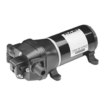
Four chamber diaphragm design; Self-priming
up to 6 ft. suction lift; Pump able to run dry
Note:
The built-in bypass valve eliminates the need
for an accumulator tank. Do not install in a
system with an accumulator tank. The tank
will interfere with the internal bypass valve.
(Available on 12 & 24V d.c. Models)
3.9 (1.8)
MODEL*
VOLTS
4405-143
12V dc
4405-343
24V dc
4405-443
32V dc
* CE fully suppressed models are identified by a prefix "R" and a CE mark on the label. (i.e. R4405-343).
Self Declaration Of Conformance (SDOC) is available upon request.
Pump Series
4405-XXX
3.75 (95)
AMP DRAW
@ 10 psi (0.7 bar)
3.9
2.0
1.3
Dimensions - Inches (mm)
Height Width
Length lb. (kg)
6.3 (160)
FLOW
PRESSURE SWITCH
GPM (l/min)
MAX psi (bar)
3.3 (12.5)
3.3 (12.5)
3.3 (12.5)
Weight
8.2 (208)
35 (2.4)
35 (2.4)
35 (2.4)
Advertisement
Table of Contents

Related Manuals for ITT Flojet 4405 Series


Summary of Contents for ITT Flojet 4405 Series
- Page 1 Four chamber diaphragm design; Self-priming up to 6 ft. suction lift; Pump able to run dry Note: The built-in bypass valve eliminates the need for an accumulator tank. Do not install in a system with an accumulator tank. The tank will interfere with the internal bypass valve.
-
Page 2: Operation
OPERATION With pump switch off, and battery fully charged, fill water toilet and shower lines. When all valves are shut off tank, open all faucets then turn pump switch on. Water pump will stop. Should pump fail to stop, turn switch off will begin to flow, when water is free of air, turn faucets and see the trouble shooting guide. -
Page 3: Troubleshooting
WIRING STEP I STEP 3 Use 14 gauge stranded wire to 20’, 12 gauge to 50’, Install 10-15 amp fuse protection on the positive lead for from power source. the -143 model, use a 7 amp fuse for the -343 and a 5 STEP 2 amp fuse for -443 model. - Page 4 5. Retighten set screw securely. Set screw head must 8. Install check valve (2) into upper housing (1) and push in. bepositioned facing motor covering seam (indentation). 9. Assemble on to lower housing (4), align 4 screws on to (Positioning of this screw is critical to avoid misalignment and motorby rotating lower housing (4) if necessary to align feet.
-
Page 5: Warranty
Tel: (519) 821-1900 Tel: 045-475-8906 Tel: +49-40-53 53 73-0 Fax: (949) 859-1153 Fax: +44 (0) 1992 467132 Fax: (519) 821-2569 Fax: 045-475-8908 Fax: +49-40-53 53 73- © Copyright 2001, ITT Industries Printed in U.S.A. All Rights Reserved Form: 81000-224 11/01...
Need help?
Do you have a question about the Flojet 4405 Series and is the answer not in the manual?
Questions and answers