Table of Contents
Advertisement
Advertisement
Table of Contents

Related Manuals for ITT Goulds Pumps 3415


Summary of Contents for ITT Goulds Pumps 3415
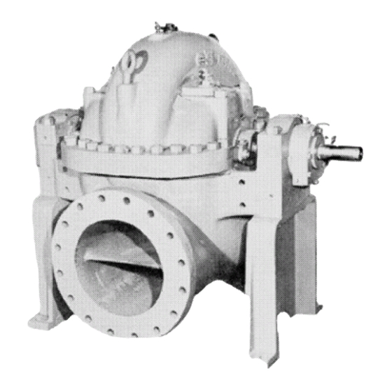
- Page 1 Installation, Operation, and Maintenance Manual Model 3415...
-
Page 3: Table Of Contents
Table of Contents Table of Contents 1 Introduction and Safety ............................ 3 1.1 Important Safety Notice..........................3 1.2 Safety warnings............................3 1.3 Safety ................................ 4 1.4 General precautions ..........................5 1.5 ATEX Considerations and Intended Use....................8 1.6 Parts ................................9 2 Installation................................ - Page 4 9 Ordering of Spare Parts ..........................53 9.1 Spare parts.............................. 53 9.2 Instructions for ordering spare parts......................54 10 Parts Listings and Cross-Sectional Drawings.................... 55 10.1 Sectional View and Parts List........................ 55 11 Local ITT Contacts ............................58 Model 3415 Installation, Operation, and Maintenance Manual...
-
Page 5: Introduction And Safety
ITT Goulds pumps will provide safe, trouble-free service when properly installed, maintained, and operat- Safe installation, operation, and maintenance of ITT Goulds Pumps equipment are an essential end user responsibility. This Pump Safety Manual identifies specific safety risks that must be considered at all times during product life. -
Page 6: Safety
Trapped liquid can rapidly expand and result in a violent explosion and injury. ITT Goulds Pumps will not accept responsibility for physical injury, damage, or delays caused by a failure to observe the instructions for installation, operation, and maintenance contained in this Pump Safety Manual or the current IOM available at http://www.gouldspumps.com/literature. -
Page 7: General Precautions
Personal injuries will result if procedures outlined in this manual are not followed. ITT Goulds Pumps will not accept responsibility for physical injury, damage or delays caused by a failure to observe the instructions in this manual and the IOM provided with your equip- ment. - Page 8 Lift equipment only at specifically identified lifting points or as instructed in the current IOM. Current manuals are available at www.gouldspumps.com/literature_ioms.html or from your local ITT Goulds Pumps sales representative. Note: Lifting devices (eyebolts, slings, spreaders, etc.) must be rated, selected, and used for the entire load being lifted.
- Page 9 1.4 General precautions WARNING Make sure to properly lubricate the bearings. Failure to do so may result in ex- cess heat generation, sparks, and / or premature failure. CAUTION The mechanical seal used in an ATEX classified environment must be proper- ly certified.
-
Page 10: Atex Considerations And Intended Use
Maintenance manual (IOM) can cause serious personal injury or damage to the equipment. This in- cludes any modification to the equipment or use of parts not provided by ITT Goulds Pumps. If there is any question regarding the intended use of the equipment, please contact an ITT Goulds representative before proceeding. -
Page 11: Parts
The code classification marked on the equipment must be in accordance with the specified area where the equipment will be installed. If it is not, do not operate the equipment and contact your ITT Goulds Pumps sales representative before proceeding. -
Page 12: Installation
2 Installation 2 Installation 2.1 Storage, uncrating and handling Storage Goulds normal domestic storage preparation is suitable for protecting the pump during shipment in cov- ered trucks. It also provides protection during covered storage at the jobsite, and for a short period be- tween installation and startup. -
Page 13: Installation - Horizontal Pumps
2.4 Installation - horizontal pumps Vertical Vertical pumps may be mounted directly on a pit, using either the pump support plate only or in conjunc- tion with a pit or tank cover. The units are shipped completely assembled except for motor, pit cover ( if any), and float controls. - Page 14 2.4 Installation - horizontal pumps Figure 3: Concrete foundation Figure 4: Wedge placement Disconnect coupling between pump and driver. NOTICE: Spider-insert couplings, as shown in Figure 5: Spider-insert coupling on page 12, need not be disconnected. Figure 5: Spider-insert coupling By adjustment of wedges, bring the bedplate to an approximate level and provide the proper dis- tance above the foundation for grouting (¾"...
-
Page 15: Alignment Procedures
2.5 Alignment procedures poured to expel the air and completely fill the space under the bedplate to the level of the grout hole. Strike along top of dam with trowel to give a neat finished appearance. Allow grout to hard- en at least 48 hours. - Page 16 2.5 Alignment procedures Pumpage Temperature Set Motor Shaft Above Ambient Temperature Ambient .004" to .006" Low 100ºF .002" to .004" Low 200ºF .000" to .002" Low 300ºF .000" to .002" High Pedestal Mounted Units Figure 7: Pedestal mounted units Set motor shaft .002" - .004" low regardless of pumpage temperature. Casing Mounted Units Figure 8: Case mounted units Pumpage Temperature Above Am-...
- Page 17 2.5 Alignment procedures Figure 9: Parallel alignment check Spider-insert couplings Place a straight edge across both coupling hubs at four points 90 degrees apart. The unit will be in parallel alignment when the straight edge rests evenly on both halves. See Figure 9: Parallel alignment check on page Flexible spacer couplings...
-
Page 18: Piping - General
2.6 Piping - general Spider-Insert Couplings The normal gap ( distance between hub and insert) is approximately 1/16". However, the cou- pling manufacturer's instructions should be followed. Check alignment by using calipers at 90° in- tervals on the circumference on the outer end of hubs. When caliper measurements are identical, the unit is in angular alignment. -
Page 19: Piping - Suction
2.7 Piping - suction Such installations require extremely careful and precise attention to hot alignment procedures. Refer to 4.5 Alignment - final on page 31 On units handling corrosives, the piping can be arranged so that corrosives can be flushed from pump prior to opening unit for service. - Page 20 2.7 Piping - suction Reducers, if used, should be eccentric and preferably at the pump suction flange sloping side down. Figure 16: A centrifugal pump should never be throttled on the suction side. Suction strainers, when used. should have a net "free area" of at least three times the suction pipe area.
- Page 21 2.7 Piping - suction Figure 18: Figure 19: Figure 20: The velocity of the water approaching the pump suction pipe should be kept to a maximum of one foot per second to avoid air being drawn into the pump. Pump suction inlet velocities and submergence (the height of the water above the pump inlet) are two additional factors that must be considered.
-
Page 22: Piping - Discharge
2.8 Piping - discharge The suction pipe should be sized to obtain a flow velocity of 4 to 7 feet per second. Changes in flow di- rection should be avoided wherever possible, especially near the pump suction. A reducer at the pump suction flange to smoothly accelerate and stabilize flow into the pump is desirable. -
Page 23: Connection Of Coupling
2.11 Connection of coupling 2.11 Connection of coupling Connect coupling. Follow the manufacturers instructions. Spider-Insert type couplings are pre-assem- bled. If a coupling guard is furnished with the unit, make sure it is securely fastened. Model 3415 Installation, Operation, and Maintenance Manual... -
Page 24: Preparation For Operation
3 Preparation for Operation 3 Preparation for Operation 3.1 Pump Bearings Oil lubrication Oil lubricated pumps are not lubricated at the factory. A high quality turbine oil, with rust and oxidation inhibitors, should be used. Constant level oilers are supplied with most oil lubricated pumps. They are included in the box of fittings which accompanies the pump. -
Page 25: Driver Bearings And Coupling
3.1 Pump Bearings Vertical pump bearings The bearing above the pump support plate is a ball bearing and is grease lubricated. Follow previous instructions for grease lubrication. The pump steady bearings (below the pump support plate) are sleeve type and made of various materi- als depending upon the application of the pump. -
Page 26: Connection Of Sealing Liquid Or Grease Lubricator (Packed Box)
3.1 Pump Bearings To pack the stuffing box, install the packing and lantern ring in the proper sequence. Each ring should be installed separately. Firmly seat each ring. Use of a wooden split bushing is recommended. See on page 24. Use gland to jack the bushing and ring into the box. Stagger joints in each ring 90 degrees. Make sure center of lantern ring lines up with flush tap in the stuffing box. -
Page 27: Connection Of Cooling Water Piping
3.1 Pump Bearings Stuffing box pressure may be below atmospheric pressure due to pump running with suction lift, or when suction source is under vacuum. Under these conditions, the packing will not be cooled Sealing liquid Sealing liquid may be supplied by recirculation of pumpage through a line from the casing to the stuffing box. -
Page 28: Connection Of Drain Pipping
3.1 Pump Bearings line permits accurate regulation. Cooling water can be circulated through the stuffing box water jacket (if any) in addition to the external flush. Cool liquid flushing - product cooling In this arrangement, pumped liquid is piped from the pump casing, cooled in an external heat ex- changer, then injected into the seal chamber. -
Page 29: Starting Pump
4 Starting Pump 4 Starting Pump 4.1 Checking for free turning Rotate shaft by hand to be sure rotating element is free. If element rubs or binds: Check alignment. Pipe loads should be removed. Check impeller clearance (if external adjustment is possible) as outlined in Sect 6.2 Impeller clearance adjustment on page If unit is equipped with leveling bolts on frame or casing foot, check to be sure that bolts are not... - Page 30 4.3 Priming When pump is installed as shown in Figure 22: Suction supply above pump on page 27, pump will prime itself. Open gate valve on suction and close discharge gate valve. Open air vent valves until all air is ex- pelled and water flows through openings.
- Page 31 4.3 Priming Figure 24: Priming with foot valve In either of these methods (1) and (2), the pump will remain primed, provided foot valve is tight. Any failure, however, of foot valve when pump is standing idle, will permit the pump to lose its prime through leakage from stuffing boxes.
-
Page 32: Initial Inspection After Starting
4.4 Initial inspection after starting suction pipe and pump casing. When all air is evacuated, start pump, close valve "S' and valve "E". and open discharge gate valve. Figure 26: Priming by automatic primer pump Where there is a fluctuating suction lift that occasionally might drop below the normal limits of the pump, or for installations where there is any quantity of air entrained in the pumpage, the system shown in Fig- ure 27: on page 30... -
Page 33: Alignment - Final
4.5 Alignment - final during this period, frequent attention and careful adjustments are necessary. Refer to 5.1 Stuffing box on page 32 Mechanical seal The mechanical seal was adjusted at the factory. If the seal leaks slightly when the pump is first started, a few hours run-in will allow seal to adjust itself. -
Page 34: Operation
5 Operation 5 Operation 5.1 Stuffing box Stuffing boxes with packing rings, less quenching liquid or grease lubricator: Periodically inspect the stuffing box to see that there is sufficient leakage to lubricate the packing and maintain a cool box. Never draw up packing so that the stuffing box heats, as this will cause damage to both packing and sleeve. -
Page 35: Operating At Reduced Head
5.3 Operating at reduced head Bearing temperature relay which will shut the unit down if the bearing temperature exceeds a predetermined minimum. Low suction pressure control which will shut off the unit should the suction pressure drop below a pre-established minimum. A centrifugal pump should never be throttled for capacity adjustment on the suction side. -
Page 36: Maintenance
6 Maintenance 6 Maintenance 6.1 Lubrication Oil lubrication (refer to 3.1 Pump Bearings on page 22 for oil specs. Ring oil lubricated ball bear- ings are standard on all Model 3415 units. The bearings are not lubricated at the factory. Remove adjustment assembly from oiler. -
Page 37: Impeller Clearance Adjustment
6.2 Impeller clearance adjustment bearing housing end covers. Grease lubricated bearings are lubricated at the factory. Do not grease at too frequent intervals. To grease bearings: Remove relief plugs on bearing end covers. See Figure 32: Grease lubricated ball bear- ings on page 37 Insert grease through fittings, while shaft is rotating, until grease appears through the re- lief plug holes. - Page 38 6.3 Disassembly of pump Remove the casing parting nuts. Remove dowel pins (1A). Loosen top half casing by inserting four ½"-13 NC bolts into parting flange. Remove top half casing using the eye bolts. Do not use eye bolts to lift enter pump. Exercise care to prevent the gasket from tearing. Remove bearing caps.
- Page 39 6.3 Disassembly of pump Figure 31: Ring oil lubricated ball bearings Figure 32: Grease lubricated ball bearings (a-1) Remove bearing end covers and oil rings (b-1) Remove bearing end covers. Preserve gaskets. from each end of shaft. (a-2) Loosen set screws in oil throwers and (b-2) Slide deflectors toward shaft sleeves.
- Page 40 6.3 Disassembly of pump C. Ring oil lubricated bearings Figure 33: Ring oil lubricated bearings The first fours steps in the disassembly procedure of sleeve bearings are outlined in Step (c-5) Lift oil rings off shaft. (c-6) Straighten tang in lock washer and remove outboard end bearing lock nut and washer.
-
Page 41: Pressure Temperature Capability
6.4 Pressure temperature capability Figure 34: Bearing housing removal 6.4 Pressure temperature capability The maximum pressure rating of the pump, including the connection of the pump and pipe flanges, can be determined from the chart and table shown below. The maximum working pressure is dependent upon both the casing limits and the mating flanges. -
Page 42: Inspection And Overhaul
6.5 Inspection and Overhaul Figure 35: NOTICE: For pressure requirements above those shown, optional casing material, flanges and bolting are available. Contact the nearest Goulds representative for details. 6.5 Inspection and Overhaul O-rings: Inspect O-rings and replace if damaged. Position them in sleeves and sleeve nuts. Wearing rings: The original clearance between the impeller and the casing wearing rings is shown in Table 3: Impeller and Wearing Ring Clearance on page... - Page 43 6.5 Inspection and Overhaul Figure 36: Impeller wearing rings: if the unit has impeller wearing rings and it is necessary to replace the rings: Remove old rings by removing the three set screws and pulling ring off hub. Clean hub and press on new ring. Drill and tap three holes 120 degrees apart with an "l"...
-
Page 44: Reassembly
6.6 Reassembly Pump Size Dimen- 8x10-22 12x14-1 14x16-1 16x18-1 10x12-2 14x16-2 16x18-2 18x20-2 Material sion Dimensions below in inches .021 .023 .023 .023 .023 .023 .023 .023 .025 .029 .029 .029 .029 .029 .029 .029 8.989 10.753 12.236 13.982 10.238 12.982 14.234 15.355... - Page 45 6.6 Reassembly Figure 37: Place O-rings under outer end of sleeves. Tighten shaft sleeve nuts against sleeves using a spanner or strap wrench. Tighten setscrews in sleeve nuts. Slide stuffing box bushings over sleeves. Position as shown in Figure 38: on page 43 so that continuous "lock"...
- Page 46 6.6 Reassembly Figure 40: Grease oil lubricat- Figure 39: Ring oil lubricated ed ball bearings ball bearings (a-1) Slide oil throwers and inboard bearing end (b-1) Slide deflectors and inboard bearing end covers on shaft. Do not damage grease seals. covers on shaft.
- Page 47 6.6 Reassembly (c-1) Slide dust covers on shaft. (c-2) Install ball bearing on outboard end of shaft. Apply a film of oil to the bearing square seat on shaft. After starting, use a driving sleeve, such as shown in 7.5 Ball bearing installation on page 48, to firmly seat the bearing.
-
Page 48: Emergency Ball Bearing Replacement
6.7 Emergency ball bearing replacement Replace the bearing caps and tighten the nuts evenly. Make sure that the caps are replaced on the same end from which they were removed and the match-marks line up. Check for free turn- ing. Place the parting gasket in position on the lower half casing. -
Page 49: Care And Maintenance Of Bearings
7 Care and Maintenance of Bearings 7 Care and Maintenance of Bearings 7.1 Bearing Temperatures All bearings operate at same temperature above that of the surrounding atmosphere, unless cooled. Heat is generated within the bearing due to rolling friction, churning of oil and the drag of the race. Do not use the human hand as a thermometer. -
Page 50: Bearing Removal
7.4 Bearing removal 7.4 Bearing removal Ball bearings A puller such as the one shown in Figure 42: Bearing puller on page 48 should be used. The puller bar must be square with the end of the shaft at all times in order to keep even pressure on the outer circumference of the bearing. - Page 51 7.5 Ball bearing installation bearing must be kept square at all times. Once the bearing is located on the shaft, a driving sleeve, such as the one shown in Figure 44: on page 49 should be used. The sleeve should contact the inner race of the bearing only.
-
Page 52: Trouble Checklist
8 Trouble Checklist 8 Trouble Checklist 8.1 Trouble Check list No liquid delivered Pump is not primed - casing and suction pipe not completely filled with liquid. Speed too low.* Discharge head too high. Check system head (particularly friction loss). Suction lift too high (suction pipe may be too small or long, causing excessive friction loss), Check with vacuum or compound gauge. - Page 53 8.1 Trouble Check list Impeller diameter may be too small. Mechanical defects: • Impeller clearance too great • Impeller damage Wrong direction of rotation or impeller installed backwards. Be sure pressure gauge is in correct place on discharge nozzle or discharge pipe. * When directly connected to electric motors, check whether motor wiring is correct and receives full volt- age.
- Page 54 8.1 Trouble Check list Mechanical defects: • Shaft bent. • Rotating parts bind, are loose or broken. • Bearings worn out. • Coupling misaligned. High bearing temperature Refer to 7.1 Bearing Temperatures on page 47 Pump and driver misalignment. Pump capacity too low. Improper lubrication.
-
Page 55: Ordering Of Spare Parts
9 Ordering of Spare Parts 9 Ordering of Spare Parts 9.1 Spare parts To ensure against possible and costly downtime periods, especially on critical services, it is advisable to have spare parts on hand. The most desirable parts to have on hand are the following: Horizontally split case pumps Rotating element: this is a group of assembled parts, including bearings, bearing hous- ings, shaft, impeller(s), wearing rings, stuffing box bushings, and all rotating parts except... -
Page 56: Instructions For Ordering Spare Parts
9.2 Instructions for ordering spare parts Stuffing box packing (if any) - one set for each stuffing box. Stuffing box gland packing (if any) - one set. Shaft sleeve - if any. Ball bearings - one of each. Shaft nut (if any). Bearing locknut and washer (if any). -
Page 57: Parts Listings And Cross-Sectional Drawings
10 Parts Listings and Cross-Sectional Drawings 10 Parts Listings and Cross-Sectional Drawings 10.1 Sectional View and Parts List Figure 45: Parts list and materials of construction Model 3415 Installation, Operation, and Maintenance Manual... - Page 58 10.1 Sectional View and Parts List Material Item Part Name B.F. A.L. A.E. 316 SS AI/316 R.E. pump 1 upper Casing 1003 1003 1103 1003 1 lower Impeller 1103 1000 1103 Wearing ring, casing 1106 1000 1106 Lantern ring 1102 1000 1102 1 set...
- Page 59 10.1 Sectional View and Parts List No. Cu. P. % NI. 84-8 4-6 4-6 4-6 - 4.5 1.75 .05- 0.75 .10- Symbol 1000 - Cast iron - corresponds to ASTM A278 Class 25 1003 - Cast iron - corresponds to ASTM A278 Class 30 316 - corresponds to AISI Type 316 (wrought) or ASTM A296 CF-8M (Cast) Construction details...
-
Page 60: Local Itt Contacts
11 Local ITT Contacts 11 Local ITT Contacts Model 3415 Installation, Operation, and Maintenance Manual... - Page 61 Visit our website for the latest version of this document and more information: http://www.gouldspumps.com Goulds Pumps Inc. 240 Fall Street Seneca Falls, NY 13148 Form IOM.3415.en-US.2021-09 ©2021 ITT Corporation The original instruction is in English. All non-English instructions are translations of the original instruction.
Need help?
Do you have a question about the Goulds Pumps 3415 and is the answer not in the manual?
Questions and answers