Table of Contents
Advertisement
Advertisement
Chapters
Table of Contents

Related Manuals for Sekonic SR-3500


Summary of Contents for Sekonic SR-3500
- Page 1 Operating manual...
- Page 2 Introduction Introduction Thank you very much for purchasing our product. Please read the operating manual before using this product, and be sure to use it properly. After reading this operating manual, be sure to keep it in a place that you can access at any time. This equipment has been tested and found to comply with the limits for a Class B digital device, pursuant to Part 15 of the FCC Rules.
-
Page 3: Table Of Contents
Setting min. density level ................41 Setting density balance .................. 42 Setting reading side ..................43 Setting hopper mode ..................44 Setting paper weight ..................46 Setting paper hold(SR-3500) ................47 Error detection settings ................... 48 Buzzer settings Buzzer control ....................50... - Page 4 Table of contents Stacker settings ....................52 Printer settings Printer control ....................53 SR-2300 SR-6500 mode 1. Character size setting ................... 54 2. Character interval setting ................55 SR-600 SR-9000 mode 1. Character size setting ................... 57 2. Character magnifi cation setting ..............58 3.
- Page 5 Table of contents Barcode readable area ................... 92 Barcode reading position adjustment ............94 Barcode unit precautions for use ..............96 Cleaning ......................... 97 Cleaning procedures ..................99 Service schedule ....................102 External diagram ....................104 List of menu modes ..................
-
Page 6: Safety Precautions
Safety Precautions Safety Precautions These “Safety Precautions” pages list various symbols for ensuring safe operation of this product so as to prevent users or other people from being injured, or property from being damaged. Read these precautions thoroughly and understand the meanings of the symbols before proceeding to the main text of this manual. - Page 7 If any foreign matter should enter inside, immediately turn the power switch off and remove the power plug from the outlet. Then, contact the sales shop or Sekonic. If the device continues to be used with foreign matter inside, fi re or electric shock may occur.
- Page 8 Caution Caution Do not place the device in an unstable location. Otherwise, it may fall or collapse, resulting in injury. When opening or closing the upper part of the main body, do not place your hand on the paper-feeding surface. Otherwise, fingers may be caught, resulting in injury.
-
Page 9: Before Using
Before using Before using ( SR-3500 ) Before using the device, check if all of the following items are included in the package. If components are missing or damaged, contact the store where you purchased the device. 1. Main body unit 2. - Page 10 Before using Stacker unit (Option) * See the installation manual for components to be used for installation. 1. Stacker 2. Main tray 3. Selection tray 2. Strage bag Printer unit (Option) (Transparent plastic bag) 1. Ink cartridge...
- Page 11 Before using Before using ( SR-6500 ) Before using the device, check if all of the following items are included in the package. If components are missing or damaged, contact the store where you purchased the device. 1. Main body unit 2.
-
Page 12: Power Cord List For Europe
Before using Power cord list for Europe Power cord list for Europe As stated on page 7 of this manual, the machine includes a representative variety of power adapters. If none of the included adapters match the power outlets in your location, please fi... -
Page 13: Warranty
Warranty Warranty The cost-free warranty period for this product extends for one year after delivery. The company will repair malfunctions arising during this period free of charge if they are determined to be the company’s responsibility. In the event repairs are necessary, as a general rule the company will keep the product temporarily to carry out such repair work. -
Page 14: Precautions For Use
Precautions For Use Precautions For Use Handle the device with the following points in mind to enable full use of its functions. • Precautions regarding installation Do not place the device in the following places. Otherwise, failures could result such as paper jams, reading errors, or the unit could become inoperative. In direct sunlight or near a heating device. - Page 15 Precautions For Use Handling precautions (continued) (11) Do not apply strong loads to the tray, as it may bend or break. (12) Because the aligning roller section has used the magnet, do not bring close a floppy disk and a magnetic card etc.. It becomes cause of data damage.
- Page 16 Precautions For Use (14) Make sure to observe the following points when you handle the device and USB cables. Otherwise, mechanical failure or damage may be caused. * Do not forcibly pull or bend the USB cable. * Always hold the plug when you insert or pull out the USB cable. Never apply excessive force to the cable.
-
Page 17: Names Of Parts
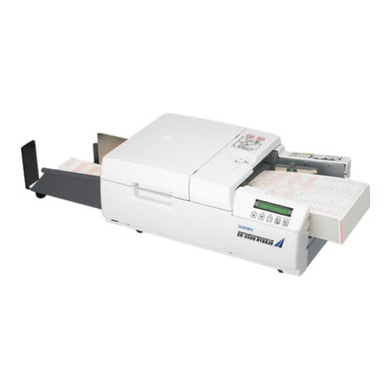
Names of parts Names of parts ( SR-3500 ) Aligning roller Paper weight setting dial Interlock Side guide Lock lever Power switch Paper feeding table (hopper) Display panel (LCD) Operating buttons Side guide knob Interface Power connector -16-... -
Page 18: Names Of Parts
Names of parts Names of parts ( When stacker unit is installed ) SR-6500 is equipped with the stacker unit standardly Paper weight setting dial Aligning roller Interlock Side guide knob Lock lever Side guide Power switch Paper feeding table (hopper) Display panel (LCD) Operating buttons... -
Page 19: Operating Panel Functions And Operating Instructions
Names of parts Operating panel functions and operating instructions Operating panel functions and operating instructions The operating panel has fi ve kinds of switches. The switches don’t work while the machine is performing a function. FEED/ENTER DOWN MENU CLEAR/EXIT There are two modes: normal mode and menu mode. In normal mode, the machine is connected to a computer and is controlled by commands from the host. -
Page 20: Product Specifi Cations
Product specifi cations Product specifi cations ( SR-3500 ) Sensor Reading Single sided, [double-sided] (* You need an optional back-surface reading unit for double-sided reading.) Darkness levels 16 levels (internal 256 levels) Light source color infra red light (940nm) [visible red light (660nm)] Pitch (inch) 1/6”, 0.2”, 0.25”, 0.3”... - Page 21 Product specifi cations Product specifi cations ( SR-6500 ) Sensor Reading Single sided, [double-sided] (* You need an optional back-surface reading unit for double-sided reading.) Darkness levels 16 levels (internal 256 levels) Light source color infra red light (940nm) [visible red light (660nm)] Pitch (inch) 1/6”, 0.2”, 0.25”, 0.3”...
-
Page 22: Operation
Operation Preparation Operation Preparation (SR-3500) Protecting tapes are attached to the main device in the following positions to protect it from vibration and shock during transportation. Remove the protecting tapes after placing the device in an appropriate location. Protecting tapes... - Page 23 Operation Preparation Connect the power cord to the main device. Connect the power cord to the power outlet. -22-...
- Page 24 Operation Preparation Operation Preparation (when stacker unit installed) Install the main tray on the main body unit. Hook the tabs on the end of the main tray into the slots on the main device’s paper discharge side. Main tray Install the selection tray on the main body unit. Hook the tabs on the end of the selection tray into the slots on the main device’s paper discharge side.
- Page 25 Operation Preparation Connect the power cord to the power outlet. -24-...
-
Page 26: Turning Power On
Operation Turning power on Turning power on Turn the power on. The following message appears on the display panel (LCD). OMR is initialized. The motor and other components are activated to check startup conditions. Check if the following message appears on the display panel (LCD). When error messages may appear between steps , respond according to P.102(Error displays and countermeasures). -
Page 27: Loading Paper
Operation Loading paper Loading paper Load paper with the timing marks on the left side of the hopper. The hopper is set to drop when the power is turned on, but if it’s still raised, press the DOWN switch in normal mode to lower the hopper. At this time, align paper carefully. Pay particular attention to the leading edges of the paper because feeding errors may occur unless the paper is properly aligned. - Page 28 Operation Loading paper Note) 1) The aligning roller is fi xed with the magnet.Check that there is not a gap and a fl oating on the adsorption aspect. In case of a certain pressing the panel side, make stick. 2) Because the aliging roller section has used the magnet, do not bring close a fl...
-
Page 29: Setting Paper Weight
Operation Setting paper weight Setting paper weight The device is equipped with a function to detect double-feeding (DF) errors. Conduct [Paper Weight]*1 according to the thickness of the paper to be used. *1 Setting reading (initially set to a paper weight of 105g/m S e e “Data reading settings setting paper weight”... -
Page 30: Marking Instructions
Marking instructions Marking instructions Marks readable by this device are as follows. Mark size: 0.5 x 3mm or more (standard mark) Readable writing instruments: pencils (black, HB or darker), ballpoint pens (black or blue) Readable marks: (Good mark example) (Bad mark example) Readable darkness: PCS 0.6 or darker Readable mark darkness can be adjusted. -
Page 31: Connecting To A Computer
Set the computer communication setting by checking your computer or software manuals. 1 ) There are times when it does not operate normally due to the environment of use. See the following pages to set the communication setting for this device. SR-3500 mode ....P.31 Operating mode... -
Page 32: Operating Mode
Connecting to a computer Operating mode Select the SR-3500,SR6500 mode as the operating mode. MENU Press the switch to enter the menu mode. DOWN Use the switches to select the mode shown below. (SR-3500) (SR-6500) FEED/ENTER Press the switch to start [Operation Mode] setting. -
Page 33: Interface Settings
Connecting to a computer Interface settings MENU Press the switch to enter the menu mode. DOWN Use the switches to select the following parameters, FEED/ENTER and press the switch. DOWN Use the switches to select the following parameters, FEED/ENTER and press the switch to begin [Device ID] setting. -
Page 34: Rs-232C
(“ ” mark fl ashes in the fi rst column of the fi rst line on the LCD.) DOWN Use the switches to select the SR-600 mode. Operation mode setting values (SR-3500) • SR-600 mode • SR-3500 mode Operation mode setting values (SR-6500) • SR-9000 mode • SR-6500 mode FEED/ENTER Press the switch to save the selected mode into memory. -
Page 35: Interface Settings
Connecting to a computer RS-232C Interface settings 2-1. Setting baud rate MENU Press the switch to enter the menu mode. DOWN Use the switches to select the following parameters, FEED/ENTER and press the switch. DOWN Use the switches to select [Baud Rate] setting, FEED/ENTER and press the switch. -
Page 36: Setting Parity
Connecting to a computer RS-232C DOWN Use the switches to select [Character Bit Length] setting, FEED/ENTER and press the switch. (“ ” mark fl ashes in the fi rst column of the fi rst line on the LCD.) DOWN Use the switches to set the value. -
Page 37: Setting Stop Bit
Connecting to a computer RS-232C 2-4. Setting stop bit MENU Press the switch to enter the menu mode. DOWN Use the switches to select the following parameters, FEED/ENTER and press the switch. DOWN Use the switches to select [Stop Bit] setting, FEED/ENTER and press the switch. -
Page 38: Setting Character Code
Connecting to a computer RS-232C DOWN Use the switches to set the value. Flow control setting values • RS/CS • Xon/Xoff • None FEED/ENTER Press the switch to save the setting value into memory. (The fl ashing “ ” mark disappears from the LCD.) CLEAR/EXIT Keep pressing the switch until it returns to normal mode,... -
Page 39: Data Reading Settings
Data reading settings Setting column Data reading settings This section explains how to change various sheet-reading settings. All settings can also be made using computer commands. Setting column Set the column. The number of columns is different depending on the reading sensor. Sensor pitch Setting range Default value... -
Page 40: Setting Reading Method
Data reading settings Setting reading method Setting reading method Setting mark-reading method. There are six kinds of reading methods: “Top-end timing control type,” “Bottom-end timing control type,” “Direct under type,” “FACOM,” “Mark to mark type (without top-end margin reading),” and “Mark to mark type (with top-end margin reading).” When setting to “top-end timing control type”... - Page 41 Data reading settings Setting reading method Setting magnifi cation when timing control types are selected MENU Press the switch to enter the menu mode. DOWN Use the switches to select the following parameters, FEED/ENTER and press the switch. DOWN Use the switches to select [Magnifi...
-
Page 42: Setting Min. Density Level
(The fl ashing “ ” mark disappears from the LCD.) CLEAR/EXIT Keep pressing the switch until it returns to normal mode, MENU or press the switch to return to normal mode. SR-600 SR-600 SR-600 SR-3500 SR-3500 SR-3500 SR-9000 SR-9000 SR-9000 SR-6500 SR-6500 SR-6500 mode... -
Page 43: Setting Density Balance
Data reading settings Setting density balance Setting density balance You can set the density balance level when using the SR-600/SR-9000 operating mode. Density balance can be set so that when marks are read, marks lighter than the set density balance will be ignored, and marks darker than the set density balance will be detected. Density balance can be set from 1 to 15. -
Page 44: Setting Reading Side
Data reading settings Setting reading side Setting reading side You can set the reading side when the optional back-sided reading unit is installed. The reading side can be set to either “single side” or “double side.” When reading single-sided sheets, if you set the reading side to “single side,” the back side won’t be read. -
Page 45: Setting Hopper Mode
Data reading settings Setting hopper mode Setting hopper mode Setting the hopper mode for reading sheets. The hopper mode can be set to either “ADF” or “manual feed.” If you set it to “manual feed,” you need to set the sheet insertion waiting time. MENU Press the switch to enter the menu mode. - Page 46 Data reading settings Setting hopper mode DOWN Use the switches to select [Wait Time for Form] setting, FEED/ENTER and press the switch. (“ ” mark fl ashes in the fi rst column of the fi rst line on the LCD.) MENU DOWN Use the...
-
Page 47: Setting Paper Weight
Data reading settings Setting paper weight Setting paper weight Set detection sensitivity In the same paper weight as seat of use to detect double-feeding errors. Paper weight can be set according to the following fi ve types: “Automatic,” “84g/m ,” “105g/ ,”... -
Page 48: Setting Paper Hold(Sr-3500)
When paper hold setting is done, after reading, without discharging the sheet you keep on the inside of this device.The processing number of cards improves with this operation.(It is the same operation as SR-3500 mode.) However It cannot maintain compatibility when the software is kept using with replacing OMR SR-600... -
Page 49: Error Detection Settings
Error detection settings Error detection settings Error detection settings for this device differ depending on the operating mode. See the following table for settings. All settings can also be made using computer commands. SR-3500 mode Default SR-600 mode Default SR-6500 mode... - Page 50 Error detection settings DOWN Use the switches to select individual error detection setting values. (See the previous table for setting values.) FEED/ENTER Press the switch to save individual setting values into memory. (The fl ashing “ ” mark disappears from the LCD.) CLEAR/EXIT Keep pressing the switch until it returns to normal mode,...
-
Page 51: Buzzer Settings
Buzzer settings Buzzer control Buzzer settings You can set the device to either use the buzzer or not use it. If you set it to use the buzzer, you can set the volume and tone. If you set it not to use the buzzer, the buzzer will not sound. Buzzer control MENU Press the... -
Page 52: Buzzer Sound Adjustment
Buzzer settings Buzzer sound adjustment Buzzer sound adjustment MENU Press the switch to enter the menu mode. DOWN Use the switches to select the following parameters, FEED/ENTER and press the switch. DOWN Use the switches to select [Buzzer Sound Adjustment] setting, FEED/ENTER and press the switch. -
Page 53: Stacker Settings
Stacker settings Stacker settings (when stacker unit is installed) You can set the paper discharge direction in SR-600/SR-9000 mode. MENU Press the switch to enter the menu mode. DOWN Use the switches to select the following parameters, FEED/ENTER and press the switch. -
Page 54: Printer Settings
Printer settings Printer control Printer settings (when stacker unit or printer unit are installed) A character is 12 x 9 pixels. Though character height is fi xed (about 3mm), widths can vary. However, the number of pixels (9 pixels) does not change, so if you enlarge a character, the space between pixels 12 pixels increases, making the character appear lighter. -
Page 55: Character Size Setting
SR-3500,SR-6500 mode SR-3500,SR-6500 mode Character size setting ........... P.54 Character interval setting ..........P.55 • See P.54 and subsequent pages for SR-3500,SR-6500 mode. SR-600,SR-9000 mode Character size setting ........... P.57 Character magnifi cation setting ........P.58 Character interval setting ..........P.59 •... -
Page 56: Character Interval Setting
Printer settings SR-3500,SR-6500 mode DOWN Use the switches to set the value. Character size setting values 3.2 - 6.4 (mm) 0.8mm increments FEED/ENTER Press the switch to save the setting value into memory. (The fl ashing “ ” mark disappears from the LCD.) - Page 57 Printer settings SR-3500,SR-6500 mode MENU Press the switch to enter the menu mode. DOWN Use the switches to select the following parameters, FEED/ENTER and press the switch. MENU DOWN Use the switches to select [Character Pitch] setting, FEED/ENTER and press the switch.
-
Page 58: Sr-9000 Mode
Printer settings SR-600,SR-9000 mode SR-600,SR-9000 mode Character size setting The width of a character can be set in fi ve increments. Size (a) 3.2mm About 3mm 4.0mm 4.8mm 5.6mm 6.4mm MENU Press the switch to enter the menu mode. DOWN Use the switches to select the following parameters, FEED/ENTER... -
Page 59: Character Magnifi Cation Setting
Printer settings SR-600,SR-9000 mode Character magnifi cation setting Width can be magnifi ed between 1 to 15 times. Character width = size x magnifi cation MENU Press the switch to enter the menu mode. DOWN Use the switches to select the following parameters, FEED/ENTER and press the switch. -
Page 60: Character Interval Setting
Printer settings SR-600,SR-9000 mode Character interval setting The space between printed characters can be increased between 0 to 99 pixels. The actual character interval (in mm units) is determined by the “size,” “magnifi cation,” and “interval” settings. Character interval (b) = character interval increment x (magnifi cation + interval + 1) Size character interval increment 3.2mm... - Page 61 Printer settings SR-600,SR-9000 mode [Setting example 1] When the size is set at 3.2mm, the magnifi cation is 1, and the interval is 0 pixel. Character interval = 0.4 x (1 + 0 + 1) = 0.8mm 0.8mm [Setting example 2] When the size is set at 6.4mm, the magnifi...
-
Page 62: Barcode Settings
Barcode settings Barcode control Barcode settings ( when barcode unit is installed ) You can set the barcode control in SR-3500,SR-6500 mode. Barcode control MENU Press the switch to enter the menu mode. DOWN Use the switches to select the following parameters,... -
Page 63: Low Power Consumption Settings
Low power consumption settings Sleep duration Low power consumption settings This device can be set to reduce power consumption in standby mode. The low-power consumption settings make the device automatically reduce power consumption when it is not used for a certain period. Sleep mode = low-power consumption condition that it automatically switches to when it is not used for a set time (sleep duration). -
Page 64: Standby Duration
Low power consumption settings Standby duration Standby duration MENU Press the switch to enter the menu mode. DOWN Use the switches to select the following parameters, FEED/ENTER and press the switch. DOWN Use the switches to select [Time for Standby] setting, FEED/ENTER and press the switch. -
Page 65: Displaying Various Information
Displaying various information Displaying the version Displaying various information This section explains how to display various setting information. Displaying the version This displays the versions of the “main body unit,” “front side reading unit,” “back side reading unit,” “stacker unit,” “printer unit,” “barcode unit” and other items. (“Back side reading unit,” “stacker unit,”... -
Page 66: Displaying Front Side Reading Sensor Settings
Displaying various information Displaying front side reading sensor settings Displaying front side reading sensor settings This displays the settings for “sensor pitch” and “sensor type” for the front side reading unit in this device. MENU Press the switch to enter the menu mode. DOWN Use the switches to select the following parameters,... -
Page 67: Displaying Back Side Reading Sensor Settings
Displaying various information Displaying back side reading sensor settings Displaying back side reading sensor settings This displays the settings for “sensor pitch” and “sensor type” for the back side reading unit in this device. (This display is available only when the device has a back side reading unit attached.) MENU Press the... -
Page 68: Displaying Optional Unit Settings
Displaying various information Displaying optional unit settings Displaying optional unit settings This displays the settings for an optional unit installed in this device. MENU . Press the switch to enter the menu mode. DOWN Use the switches to select the following parameters, FEED/ENTER and press the switch. -
Page 69: Displaying Total Count
Displaying various information Displaying total count Displaying total count This displays total count in this device. MENU Press the switch to enter the menu mode. DOWN Use the switches to select the following parameters, FEED/ENTER and press the switch. DOWN Use the switches to select [Total count] display, FEED/ENTER... -
Page 70: Displaying Serial Number
Displaying various information Displaying serial number Displaying serial number This displays serial number of this device. MENU Press the switch to enter the menu mode. DOWN Use the switches to select the following parameters, FEED/ENTER and press the switch. DOWN Use the switches to select [Serial number] display, FEED/ENTER... -
Page 71: Operating Tests
Operating tests Feed test 1 Operating tests This section explains operating test procedures. Feed test 1 This test reads the check sheets included in the package to test if the device reads them properly. If the device doesn’t read the check sheets properly, the reading test will stop. Once reading of the check sheets starts, the test will continue until an error occurs or the hopper is empty. -
Page 72: Feed Test 2
Operating tests Feed test 2 Feed test 2 This test reads the check sheets included in the package to test if the device reads them properly. Even if the device doesn’t read something properly, the test will continue. Once reading of the check sheets starts, the test will continue until an error other than a reading occurs or the hopper is empty. -
Page 73: Printer Test
Operating tests Printer test Printer test The test characters is printed on the fed sheet and the sheet will be discharged. (This test will be conducted only when stacker unit and printer unit are installed.) The number of characters printed varies depending on the printer settings, and character size and interval settings. -
Page 74: Printer Jet Test
Operating tests Printer jet test Printer jet test This test is done when the printing of sheets is not possible, is not clear. ( This test will be conducted only when stacker unit and printer unit are installed. ) MENU Press the switch to enter the menu mode. -
Page 75: Options Stacker Unit
Options Stacker unit Stacker unit specifi cations Options Stacker unit SR-6500 is equipped with the stacker unit standardly, SR-3500 is equipped with it optionally. Stacker unit specifi cations (printer) Printing location Prints on top surface of fed sheet Printing method... -
Page 76: Stacker Unit (Printer) Preparation
Options Stacker unit Stacker unit preparation Stacker unit (printer) preparation Turn the power off and remove the power cord from the outlet. Open the front door of the stacker unit. Front door Disconnect the printer connector. Printer Connector Loosen the printer fi xing screw to remove it. Fixing screw -75-... - Page 77 Options Stacker unit Stacker unit preparation Lift the cartridge case lever and insert an ink cartridge. Note) Align positioning pins (2 places) of the ink cartridge with the positioning holes (2 places) of the cartridge case. Lever Positioning holes Align positioning pins Lower the cartridge case lever to lock the ink cartridge.
- Page 78 Options Stacker unit Stacker unit preparation Tighten the printer fi xing screw and connect the printer connector. Printer Connector Fixing screw Close the front door of the stacker unit. Front door Adjust the main tray regulator to the proper paper size. Regulator Main tray Connect the power cord and turn the power on.
-
Page 79: Printing Position Adjustment
Options Stacker unit Printing position adjustment Printing position adjustment Turn the power off and remove the power cord from the outlet. Open the front door of the stacker unit. Front door Disconnect the printer connector. Printer Connector Loosen the printer fi xing screw to remove it. Fixing screw -78-... - Page 80 Options Stacker unit Printing position adjustment Loosen the cartridge case fi xing screw, move the cartridge case according to the desired printing position, and tighten the screw to secure it. * The scale on the positioning sticker indicates the printing position from the edge of the paper.
- Page 81 Options Stacker unit Printing position adjustment Close the front door of the stacker unit. Front door Connect the power cord and turn the power on. Execute printer test ( S e e P.72). * If the printing position is misaligned, adjust it. Fixing screw Positioning sticker Cartridge case...
-
Page 82: Clearing Paper Jams
Options Stacker unit Clearing paper jams Clearing paper jams Open the front door of the stacker unit. Front door Open the jam release levers (4 levers) or turn the jam-removing knob to remove jammed paper. Jam-removing knob Jam release levers After removing jammed paper, close the jam release levers. -
Page 83: Stacker Unit Precautions For Use
Options Stacker unit Stacker unit precautions for use Stacker unit precautions for use Make sure to tightly close the jam release levers and the front door. Loose levers or a loose door may trigger paper jams. Use ink cartridges before their expiry dates. Under the following conditions, remove the ink cartridge from the device, and store it at room temperature (10-35°C) in the ink cartridge storage bag included in the package. -
Page 84: Back Side Reading Unit
Options Back side reading unit Back side reading unit If you install a back side reading unit in the device, both sides of a sheet can be read. When installing the back side reading unit, set the reading side settings at the same time. S e e “Data reading settings Setting reading side”... -
Page 85: Printer Unit
Options Printrer unit Printrer unit specifi cations Printrer unit Printrer unit is a optional equipment with SR-3500. Printer unit specifi cations Printing location Prints on top surface of fed sheet Printing method Inkjet Number of characters printed Maximum 72 characters... - Page 86 Options Printrer unit Printable area Printing after reading marks The printable area is a maximum of 230mm from the bottom edge of a sheet. [When sheet size is (L > 233)mm] (W-4) mm (L-230) mm (230-3) mm [When sheet size is (L < 233)mm] (W-4) mm (L-6) mm Printing while reading marks at the same time...
-
Page 87: Printer Uniut Preparation
Options Printrer unit Printer unit preparation Printer unit preparation Turn the power off and remove the power cord from the outlet. Remove the carrier cover. Carrier cover Lift the cartridge case lever and insert an ink cartridge. Note) Align positioning pins (2 places) of the ink cartridge with the positioning holes (2 places) of the cartridge case. -
Page 88: Printing Position Adjustment
Options Printrer unit Printing position adjustment Printing position adjustment Turn the power off and remove the power cord from the outlet. Remove the carrier cover. Carrier cover Loosen the cartridge case fi xing screw, move the cartridge case according to the desired printing position, and tighten the screw to secure it. - Page 89 Options Printrer unit Printing position adjustment S e e Execute printer test ( P.72). * If the printing position is misaligned, loosen the cartridge case fixing screw, adjust the cartridge case according to desired printing position, and tighten the screw to secure it. Fixing screw Positioning sticker Cartridge case...
-
Page 90: Printer Unit Precautions For Use
Options Printrer unit Printer unit precautions for use Printer unit precautions for use Use ink cartridges before their expiry dates. Under the following conditions, remove the ink cartridge from the device, and store it at room temperature (10-35°C) in the ink cartridge storage bag included in the package. -
Page 91: Barcode Unit / V • Barcode Unit / H
Barcode unit / V • barcode unit / H Barcode unit specifi cations Barcode unit / V • barcode unit / H If you install a barcode unit in the device, barcodes on paper can be read. Barcode unit specifi cations Barcode unit / V (vertical feeding) Reading direction Vertical feeding (bars are parallel to sheet feeding direction) - Page 92 Barcode unit / V • barcode unit / H Barcode unit specifi cations Barcode unit / H (horizontal feeding) Reading direction Horizontal feeding (bar direction is perpendicular to sheet feeding direction) Codes JAN/EAN/UPC (module 0.33 mm,0.8 times~ 2 times) NW-7 CODE-39 CODE-93 CODE-128...
-
Page 93: Barcode Readable Area
Barcode unit / V • barcode unit / H Barcode readable area Barcode readable area The barcode readable area differs depending on the kind of barcode unit. Barcode unit / V (vertical feeding) 50mm 200mm Reading area Clear area Clear area Center Center Clear area... - Page 94 Barcode unit / V • barcode unit / H Barcode readable area Barcode unit / H (horizontal feeding) 20mm 224mm Clear area Reading area Clear area Clear area 12mm Horizontal Height of barcode direction 10mm or more deviance Barcode front edge margin or less 12mm or more 10mm or more...
-
Page 95: Barcode Reading Position Adjustment
Barcode unit / V • barcode unit / H Barcode reading position adjustment Barcode reading position adjustment Turn the power off. Remove the carrier cover. Carrier cover Loosen the barcode unit position fi xing screw, move the barcode unit according to barcode position, and tighten the screw to secure it. - Page 96 Barcode unit / V • barcode unit / H Barcode reading position adjustment check reading using a diagnostic utility. * If a reading error occurs, the barcode reading position may be misaligned, so make an adjustment. Positioning sticker Positioning screw Barcode unit If the barcode reading position is properly aligned, close the carrier cover.
-
Page 97: Barcode Unit Precautions For Use
Barcode unit / V • barcode unit / H Barcode unit precautions for use Barcode unit precautions for use When applying barcode stickers, etc. on a sheet, make sure that sheet thickness with stickers is 0.25mm or less. When applying barcode stickers, etc. on a sheet, avoid the grayed area below. 65mm Make barcodes according to the following specifi... -
Page 98: Cleaning
Cleaning Cleaning Dirty rollers, reading lenses, and sensors can cause various operational errors. Clean them regularly using the following procedures. Cleaning intervals differ depending on usage conditions (usage frequency, quality of paper used, etc.) Cleaning periods are for your reference -- clean the device soon if you notice dirt or other irregularities. Note) Always turn the power off when cleaning. - Page 99 Cleaning Double-feeding Slave rollers Reading lens prevention roller Back surface / bottom (under the cover) reading sensor (option) Double-feeding prevention roller / top Reading start detection sensor Reading lens Front surface Driving rollers reading sensor Left skew sensor Clearing Stacker unit (when stacker unit is installed) Slave rollers Slave rollers Driving rollers...
-
Page 100: Cleaning Procedures
Cleaning Cleaning procedures Cleaning procedures Main body unit Turn the power off and remove the power cord from the outlet. Grasp the lock lever to release the lock, and push the top cover up to open it. Remove the stopper. (1 screw) Clean necessary parts. - Page 101 Cleaning Cleaning procedures Stacker unit (when stacker unit is installed) Turn the power off and remove the power cord from the outlet. Open the front door of the stacker unit. Front door Open the jam release lever. Jam release lever Clean necessary parts.
- Page 102 Cleaning Cleaning procedures Close the jam release lever. Clean the remaining three parts in the same manner as in steps 3 to 5. Jam release lever Close the front door of the stacker unit. Front door -101-...
-
Page 103: Service Schedule
Service schedule Service schedule For stable operation of this device, regular replacement of components is required. See the following table, and contact us, or the store where you purchased the device, when requiring component replacement. Main body unit Replacement reference Component name Number Remarks (counter number) - Page 104 Service schedule Stacker unit (when stacker unit is installed) Replacement reference Component name Number Remarks (counter number) Driving roller / 1 500,000 or 3 years Driving roller / 2 500,000 or 3 years Driving roller / 3 500,000 or 3 years Driving roller / 4 500,000 or 3 years Driving roller / 5...
-
Page 105: External Diagram
External diagram External diagram ( SR-3500 ) ( Unit : mm) Front view 292.6 371.7 Top view Rear view Left view Right view -104-... -
Page 106: External Diagram
External diagram External diagram ( SR-6500,SR-3500 when stacker unit is installed ) ( Unit : mm) Front view Top view Rear view Left view Right view -105-... -
Page 107: List Of Menu Modes
List of menu modes List of menu modes Setting menu Setting item Setting value SR-3500 mode , SR-600 mode Operation Mode SR-6500 mode , SR-9000 mode Device ID 0 - 126 × Baud Rate 9600 , 19200 , 38400 , 57600 , 115200 ×... - Page 108 List of menu modes Setting menu Setting item Setting value Printer Control Valid , Invalid Setting of 3.2mm - 96.0mm , 0.8Pitch × Size Printer 3.2mm , 4.0mm, 4.8mm, 5.6mm, 6.4mm × (only when the stacker unit and 1 Time - 15 Time Magnifi...
- Page 109 (only when the stacker unit and the printer unit are installed) *1 Items displayed when SR-3500 mode or SR-6500 mode is selected as the operating mode. *2 Items displayed when SR-600 mode or SR-9000 mode is selected as the operating mode.
-
Page 110: Error Displays And Countermeasures
Error displays and countermeasures Error displays and countermeasures Errors Hardware errors [Main body unit] Error Explanation Code Solution Memory error 1 Internal memory error 1 None Memory error 2 Internal memory error 2 None Hopper drive error Hopper operating error None Error while downloading to Download erro... - Page 111 Error displays and countermeasures [Reading unit] Error Explanation Code Solution Line error occurred between the device and the front side reading unit. Communication error None Line error occurred between the device and the back side reading unit. Front side reading unit doesn't replay Internal com.
- Page 112 Error displays and countermeasures [Barcode unit] Error Explanation Code Solution Line error occurred between the Communication error None device and the barcode unit. Internal com. error Barcode unit doesn't reply. None Memory error None Barcode unit memory error. Error occurred with barcode Sensor error sensor.
- Page 113 Error displays and countermeasures Transmission errors Error Explanation Code Solution A non-specifi ed command code Press the CLEAR switch Command error was received. (or execute the clear error command). A non-specifi ed parameter was Press the CLEAR switch Parameter error received.
-
Page 114: Warnings
Error displays and countermeasures [Stacker unit] Error Explanation Code Solution • Remove jammed paper. A paper jam occurred at the Jam at printer printing • Press the CLEAR switch printer printing start detection start detection sensor ( o r e x e c u t e t h e c l e a r e r r o r sensor. - Page 115 Error displays and countermeasures Operation errors Error Explanation Code Solution • Release the interlock switch. Interlock on the side of the • Press the CLEAR switch Hopper stops paper-feeding roller operated. ( o r e x e c u t e t h e c l e a r e r r o r command).
- Page 116 Error displays and countermeasures [Main body unit] Error Explanation Code Solution • Remove the remaining sheet. A sheet remained in the paper • Press the CLEAR switch Form left in hopper feeding detection sensor. ( o r e x e c u t e t h e c l e a r e r r o r command).
-
Page 117: Omr Glossary
OMR glossary OMR glossary Column and Row Mark frames are in columns, timing marks are in rows..column column column column column 1st row Mark frame 2nd row 3rd row 4th row Timing mark A paper jam error caused by media when paper is being fed. There are two kinds of jams: static jams detected when the device is at rest, and operational jams detected while the device is running. - Page 118 OMR glossary Timing control type If paper has pre-printed timing marks, the scanning area (reading area) of targeted mark frames will be determined by such timing marks. Timing control type is a method to determine the reading zone based on the timing mark width.
- Page 119 Reading area Transmission interface The hardware connecting a computer and the OMR, in other words the mediating connection. The SR-3500,SR-6500 uses USB or RS-232C interfaces. Dropout color Refers to colors pre-printed or written on documents that people can see but that don’t appear when read with an image scanner or other devices.
- Page 120 OMR glossary Colors that can be used as dropout colors differ depending on the model, but with some models, even regular ballpoint pen ink drops out and cannot be used. In such cases, you need special OCR ballpoint pens that are rarely available today. See table below for relationships between wavelengths and colors.
- Page 121 OMR glossary Writing implements Readable marks and unreadable marks depend on the writing instruments used. This can also differ according to the light source that the reading sensor uses. Relationships between sensors used for OMR (light source) and writing implements Light source Readable mark colors Unreadable mark colors...
- Page 122 OMR glossary Mark to mark type If paper has pre-printed timing marks, the scanning area (reading area) of targeted mark frames will be determined by such timing marks. Mark to mark type is a method to read zones between two timing marks. Therefore, the number of timing marks in mark to mark type forms is always an even number.
- Page 124 Appendix Sheet creation reference Appendix Sheet creation reference You can use paper that you make yourself with this device in addition to the optional paper that we offer. If you make your own paper, follow the specifi cations below. Sheet size Height 110-335.6mm Width 63.5-228.6mm Do not cut or round the corners on the reference side (timing mark side).
-
Page 125: Appendix Sheet Creation Reference
Appendix Sheet creation reference Clear zones Do not print in colors other than dropout colors 0.8mm around reading zones and 0.8mm from timing mark longitudinal ends. Reading zone: The vertical direction of the data mark standard position is the height set by command, and the horizontal width refers to the area of the data mark frame width. - Page 126 Appendix Sheet creation reference (13) Paper dimensions [Direct under type sheet] 0.3 A Sheet horizontal length (W) 4 or more Pitch (P) x (row-1) Do not aggregate tolerances 0.3 A Mark frame Timing mark 0.2 A 0.3 A General tolerance ±0.2 [Unit: mm] Maximum number of columns Maximum...
- Page 127 Appendix Sheet creation reference [Direct under type card (0.25” IBM card size)] 0.2 A 0.2 A 82.55 6.35 x 11=69.85 6.35 6.35 3.5±0.1 Standard size Cut corner (*) 3.5-4.3 0.2 A 0.2 A [Unit: mm] General tolerance ±0.2 * Cut corners and round corners They help you to easily check if paper is placed in the right direction, and help you to manage paper and keep it orderly.
- Page 128 Appendix Sheet creation reference [Timing control type sheet] 0.3 A Sheet horizontal length (W) 4 or more Pitch (P) x (row-1) Do not aggregate tolerances 0.3 A Mark frame Timing mark 0.3 A General tolerance ±0.2 [Unit: mm] Maximum Maximum number of columns number Size W x L (mm)
- Page 129 Appendix Sheet creation reference [Mark to mark type sheet] 0.3 A Sheet horizontal length (W) 4 or more Pitch (P) x (row-1) Do not aggregate tolerances Should be in the center between timing marks 0.3 A Paper-feeding pitch E Mark frame Timing mark 0.3 A General tolerance ±0.2...
- Page 130 Appendix Sheet creation reference [Mark to mark type card (0.25” IBM card size)] 0.2 A 82.55 6.35 x 11=69.85 6.35 3.5±0.1 6.35 Standard size Should be in the center between timing marks 0.2 A 3.5-4.3 0.2 A General tolerance ±0.2 [Unit: mm] -vii-...
Need help?
Do you have a question about the SR-3500 and is the answer not in the manual?
Questions and answers