Table of Contents
Advertisement
Advertisement
Table of Contents

Subscribe to Our Youtube Channel
Related Manuals for Sekonic SR-1800


Summary of Contents for Sekonic SR-1800
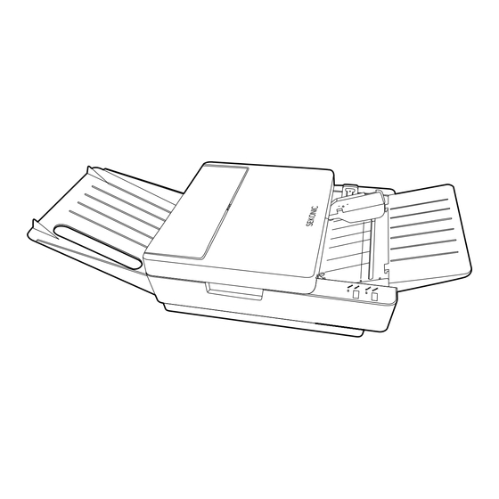
- Page 1 OPTICAL MARK READER S R - 1 8 0 0 OPERATING MANUAL...
- Page 2 SR-1800 Introduction Thank you very much for purchasing our product. Please read the operating manual before using this product, and be sure to use it properly. After reading this operating manual, be sure to keep it in a place that you can access at any time.
-
Page 3: Table Of Contents
SR-1800 Table of Contents Safety Precautions ........................4 Warranty ............................7 Precautions for Use ........................8 ■ Precautions regarding installation ..................8 ■ Handling precautions ......................8 Before Using ..........................9 ■ Before Using the Device ..................... 9 ■ Unpacking the Device ....................... 10 Names and Functions of Parts ....................11 ■ Main Body Unit........................11 ■... - Page 4 SR-1800 3 Power Saving Modes ....................28 ■ Setting Sheets ........................29 ■ Reading Sheets ......................... 32 When an error occurs: ...................... 32 ■ Checksheet Reading Test ....................32 Troubleshooting ........................34 ■ Troubleshooting ........................ 34 ■ Error Indicator ........................35 ■ Fixing Sheet Jams......................37 Cleaning ............................. 39 ■ Regular Maintenance ......................39 ■...
-
Page 5: Safety Precautions
SR-1800 Safety Precautions These “Safety Precautions” pages list various symbols for ensuring safe operation of this product so as to prevent users or other people from being injured, or property from being damaged. Read these precautions thoroughly and understand the meanings of the symbols before proceeding to the main text of this manual. - Page 6 SR-1800 Warning • Fire or electric shock may happen if this product continues to be used when there is a strange smell or sound. In such a case, immediately turn the power switch off and then remove the power plug from the outlet. After making sure that it is no longer smoking, ask the sales shop for repair service. Never attempt to repair by yourself since that may be very dangerous. • P lease do not modify or disassemble this machine. It may result in fire or electric shock. • P lease do not remove the machine´s cover (except for top cover). It may result in electric shock. Please ask the sales representative internal inspections, adjustments, and repairs.
- Page 7 SR-1800 Warning • If any foreign matter should enter inside, immediately turn the power switch off and remove the power plug from the outlet. Then, contact the sales representative or Sekonic. If the device continues to be used with foreign matter inside, fire or electric shock may occur. I f water or other substances penetrate the unit, immediately turn the power switch off and remove the power plug from the outlet. Then, contact the sales representative or Sekonic. If the device continues to be used with water or other foreign matter inside, fire or electric shock may occur. • Before moving the device, be sure to remove the power plug from the outlet. If the cable is damaged, fire or electric shock may occur. • Do not connect or disconnect the power plug if your hands are wet. Otherwise, an electric shock may occur. Caution • Do not place the device in an unstable location. Otherwise, it may fall or collapse, resulting in injury. • When opening or closing the upper part of the main body, do not place your hand on the sheet-feeding surface. Otherwise, fingers may be caught, resulting...
-
Page 8: Warranty
SR-1800 Warranty The cost-free warranty period for this product extends for one year after delivery. The company will repair malfunctions arising during this period free of charge if they are determined to be the company's responsibility. In the event repairs are necessary, as a general rule the company will keep the product temporarily to carry out such repair work. -
Page 9: Precautions For Use
SR-1800 Precautions for Use Handle the device with the following points in mind to enable full use of its functions. Precautions regarding installation Do not place the device in the following places. Otherwise, failures could result such as sheet jams, reading errors, or the unit could stop operating. -
Page 10: Before Using
SR-1800 Before Using Before Using the Device Before using the device, check if all of the following items are included in the package. If parts are missing or damaged, contact the store where you purchased the device. 1. Main body unit 1. Main body unit 2. -
Page 11: Unpacking The Device
SR-1800 Unpacking the Device The following parts are fixed with tape to prevent damage in shipping (1) The device is fixed with tapes. Remove the tapes . (5 places) Also, remove the drying agent (1) and the hopper fixing material (1) from the main body unit. -
Page 12: Names And Functions Of Parts
SR-1800 Names and Functions of Parts Main Body Unit Rear Rear Front Front Number Name Explanation Operation panel Refer to “Operation Panel” below. Hopper Part for loading sheet. Sheet feed tray Tray for sheet supply. (removable) Lock lever Adjusts width to match the sheet width. - Page 13 SR-1800 Front Front Rear Rear Number Name Explanation USB connector Port for communication via USB cable. RS-232C connector Port for communication via RS-232C. DC jack DC plug (AC adapter) connection terminal. Power switch Turns the device ON/OFF. DIP Switch cover Cover for the DIP switch.
-
Page 14: Buzzer Sound
SR-1800 Buzzer Sound This device has a built-in buzzer that indicates operating conditions and errors. Buzzer Sound Meaning Explanation When the power is on, the buzzer sounds after the self-check is completed normally. (Sounds at the same time the ERROR lamp turns off.) -
Page 15: Preparation For Use
SR-1800 Preparation for Use Prepare the device for use by following the procedure below. Reference: For information on unpacking the device, refer to “ Unpacking the Device” (P.10). Attaching the Sheet Feed Tray and Stacker Attach the sheet feed tray and stacker to the main body unit as shown in the diagrams below. -
Page 16: Connecting The Ac Adopter
SR-1800 Connecting the AC Adopter Attach the AC adapter (included) to the device. • Be sure to use the included AC adapter, otherwise a fire may result. WARNING (1) Insert the DC plug of the AC adapter into the main body unit's DC jack (2) Connect the power cord to the AC adapter and the outlet. -
Page 17: Connecting The Communication Cable
Adjust settings using the DIP switch (SW3-1 and -2). (Reference: “5 DIP Switch SW3 Settings” (P.21)) * For details on the SR-1800 mode commands, refer to the “OMR Command Reference Manual” and “API Reference Manual for Windows” on the included CD-ROM. -
Page 18: Rotary And Dip Switch Settings
SR-1800 Rotary and DIP Switch Settings The device is shipped from the factory with default settings. Configure the number of lines to read and device function settings according to its intended use. If the RS-232C port is used, configure the communication speed and data format settings. -
Page 19: Dip Switch Sw1 Settings
SR-1800 DIP Switch SW1 Settings Configure RS-232C port communication format and other settings. CAUTION · Be careful when configuring settings. Communication errors will occur if settings are incorrect. · Make sure the power is off when configuring settings. · DIP switch 1-6 (SW1-6) is the back side reader setting, unrelated to the RS-232C settings. -
Page 20: Dip Switch Sw2 Settings
SR-1800 DIP Switch SW2 Settings CAUTION · Be careful when configuring settings. Marks will be misread if the settings are incorrect. · Make sure the power is off when configuring settings. : Indicates the factory settings. Contents of setting No. of lines Timing type Control type 12 lines... - Page 21 SR-1800 SW2-5: Select automatic sheet discharge. When it is ON (factory setting) and an error related to automatic sheet discharge (see below) occurs, the sheet will be discharged automatically. (This function becomes effective when the setting for SW3-3 Sheet Hold is ON.
-
Page 22: Dip Switch Sw3 Settings
SR-1800 DIP Switch SW3 Settings CAUTION · Be careful when configuring settings. Malfunction will occur if the settings are incorrect. · Make sure the power is off when configuring settings. : Indicates the factory settings. Contents of setting Operation mode SR1800 Mode (USB connection mode) (Not used) -
Page 23: Rotary Switch Rsw2 Settings
SR-1800 Rotary Switch RSW2 Settings CAUTION · Be careful when configuring settings. Malfunction will occur if settings are incorrect. · Make sure the power is off when configuring settings. Set the paper weight to match the sheet to be used. This setting is used for double feed detection. -
Page 24: Inspecting Sheets
SR-1800 Inspecting Sheets Inspect sheets according to the following procedure to make sure there are no problems. (1) Checking for dirty or damaged sheets Check that the sheets are free from any dirt, rumples, folds, folding lines, turn-over, tears or bending. Do not make the device read sheets in which tears were mended with adhesive cellophane tape, etc. - Page 25 SR-1800 (3) Correcting curled or deformed sheets Fix curled sheets or formed sheets if they are found. If the device is forced to read curled or deformed sheets, it will tend to cause a reading error, sheet jam, no feed, double feed, or skewed feed.
-
Page 26: Handling And Storing Sheets
SR-1800 Handling and Storing Sheets Sheets are affected by their handling and ambient conditions (especially temperature and humidity) and their characteristics may change, resulting in a reading error. CAUTION: Handle and store sheets with extreme care. Handling sheets (1) Do not fold or blemish sheets, as a reading error may occur. -
Page 27: Marking Instructions
The reading sensitivity level ranges from 1 through 16, with Level 1 having the maximum reading sensitivity and Level 16 having the minimum reading sensitivity. The table below compares the reading sensitivity levels of this SR-1800 device with the conventional SR-600 device. -
Page 28: Operation
SR-1800 Operation Operation Flow Power on Power on Reference: “Checksheet Reading Test” (P.32) Reference: “Checksheet Reading Test” (P.32) Set sheets Set sheets Reading sheets Reading sheets Reading Checksheets Reading Checksheets If necessary, read the checksheet and make sure there are no If necessary, read the checksheet and make sure there are no errors. -
Page 29: Power Saving Modes
SR-1800 Power Saving Modes After turning the power on, if the device is not operated for a certain period of time, the device will automatically enter power saving mode and power consumption will be minimized. The following are two types of power saving modes:... -
Page 30: Setting Sheets
SR-1800 Setting Sheets (1) Push the lock lever down. When the hopper is lowered to the position where the sheets are set, there will be a clicking sound and it will lock. (2) Set sheets straight so that their timing marks are on the left side viewing from the sheet feed direction. - Page 31 SR-1800 CAUTION · Be careful not to bend, fold, or damage the sheets. Doing so may result in a sheet feeding error or reading error. · Make sure to loosen the sheets before using them. Double feeding may occur if they are stuck to each other due to static electricity, burr, etc.
- Page 32 SR-1800 Sheet Setting Example Sheet Setting Example Sheet Guide Sheet Guide [Good example] [Good example] [Bad examples] [Bad examples] A gap exists either on the right or left side although the sheets are aligned. A gap exists either on the right or left side although the sheets are aligned.
-
Page 33: Reading Sheets
SR-1800 Reading Sheets This section explains the procedure for reading sheets. (If you perform the checksheet reading test, please refer to “Checksheet Reading Test” (P.32)) (1) Turn the power switch on. The power turns on and the self-check begins. The READY lamp (green) and the ERROR lamp (red) both light up. - Page 34 SR-1800 (2) Set the checksheet in the hopper. Set the checksheet so that the timing marks are on the left side in the feeding direction. Set the checksheet so that the corner cut is in the upper right as shown below.
-
Page 35: Troubleshooting
SR-1800 Troubleshooting Before assuming that the device is broken, check the following. If you are still unable to solve the problem, please contact the store where you purchased the device. Troubleshooting Error Status Cause Action AC adapter and power cord are not Connect them properly. -
Page 36: Error Indicator
When an error occurs, the ERROR lamp (red) blinks on and the buzzer sounds. (If the error is hardware-related, the ERROR lamp turns on.) In SR-1800 mode, the computer can obtain the following error status information from the device by sending the command. - Page 37 SR-1800 Status Error Status Error Cause Action Information Hardware Internal error Turn off the power briefly, A1 / A 2 / ERROR lamp error then turn the power back A4/A5/ (Red) on. Check whether or not Lights up. the same error occurs. If the...
-
Page 38: Fixing Sheet Jams
SR-1800 Fixing Sheet Jams When a sheet jam occurs, fix it according to the following procedure. (1) Hold Part A of the top cover and open it, pull upward and remove it. Part A Part A Top cover Top cover Reading sensor unit... - Page 39 SR-1800 (4) Reattach the top cover. Close the top cover securely. Otherwise, it may cause poor sheet feeding. (5) If the ERROR lamp (red) is on, check (3) and (4) again. (6) The following are possible causes of the sheet jam.
-
Page 40: Cleaning
SR-1800 Cleaning Make sure to turn the power off and remove the power plug from the outlet before cleaning. Failure to do so may result in electric shock. WARNING External parts are made of plastic. Do not use benzene, paint thinner, or any other volatile substances and chemical solvents. Doing so may result in discoloring or deformation. Caution Regular Maintenance When the rollers and reading sensors become dirty, various types of malfunction problems may occur. Maintain the device regularly as discussed below. Maintenance frequency will depend on usage (frequency of use, quality of sheet used, etc.) When you become aware of dirt or other foreign objects, clean them off. -
Page 41: Cleaning Procedures
SR-1800 Cleaning Procedures (1) Make sure the power is off and the power plug is removed from the outlet. (2) Hold Part A of the top cover and open it, pull upward and remove it. Part A Part A Top cover Top cover (3) Clean the necessary parts. - Page 42 SR-1800 [Part of Reading Sensor Area to Clean] Lift the reading sensor unit and clean the surface of the lens on the bottom of the Reading sensor area reading sensor unit. For the device of double-sided reading specification, clean the surface of the lens on the main body side.
-
Page 43: Service Schedule
SR-1800 Service Schedule For stable operation of this device, regular replacement of components is required. See the following table, and contact us, or the store where you purchased the device, when requiring component replacement. Component name Number Replacement reference Remarks Sheet feed roller... -
Page 44: Product Specifications
SR-1800 Product Specifications Sensor Reading Single-sided, double-sided Darkness level 16 levels (including no mark) Light source color Near-infrared light (940nm) [visible red light (660nm)]* Pitch (inches) 1/6” Marking Standard: pencil [Visible red light: ball point pen (black, blue)]* Reading marks Size: 0.5 x 3mm or larger (recommended mark) -
Page 45: External Dimensions Diagram
SR-1800 External Dimensions Diagram 328mm(12.9 inches) 328mm(12.9 inches) -
Page 46: Omr Glossary
SR-1800 OMR Glossary Column and Row Mark frames are in columns, timing marks are in rows..... column column column column column column column column column column 1st row 1st row Mark frame Mark frame 2nd row 2nd row 3rd row... - Page 47 SR-1800 Timing control type If the sheet has pre-printed timing marks, the scanning area (reading area) of targeted mark frames will be determined by such timing marks. Timing control type is a method to determine the reading zone based on the timing mark width.
- Page 48 Reading area Transmission interface The hardware connecting a computer and the OMR, in other words the mediating connection. The SR-1800 uses USB or RS-232C interfaces. Dropout color Refers to colors pre-printed or written on documents that people can see but that don’t appear when read with an image scanner or other devices.
- Page 49 SR-1800 (5) Colors that can be used as dropout colors differ depending on the model, but with some models, even regular ballpoint pen ink drops out and cannot be used. In such cases, you need special OCR ballpoint pens that are rarely available today. See table below for relationships between wavelengths and colors.
- Page 50 SR-1800 Writing implements Readable marks and unreadable marks depend on the writing instruments used. This can also differ according to the light source that the reading sensor uses. Relationships between sensors used for OMR (light source) and writing implements Light source...
- Page 51 SR-1800 Mark to mark type If the sheet has pre-printed timing marks, the scanning area (reading area) of targeted marks frames will be determined by such timing marks. Mark to mark type is a method to read zones between two timing marks. Therefore, the number of timing marks in mark to mark type forms is always an even number.
-
Page 52: Appendix
SR-1800 Appendix Sheet creation reference You can use a sheet that you make yourself with this device in addition to the optional sheets that we offer. If you make your own sheet, follow the specifications below. (1) Sheet size Height 110-335.6mm(4.3-14 inches), Width 63.5-228.6mm(2.5-9 inches) However, Feed Length (L) must be Width (W) ×... - Page 53 SR-1800 (8) Clear zones Do not print in colors other than dropout colors 0.8mm around reading zones and 0.8mm from timing mark longitudinal ends. Reading zone: The vertical direction of the data mark standard position is the height set by command, and the horizontal width refers to the area of the data mark frame width.
- Page 54 SR-1800 (13) Sheet dimensions [Direct under type sheet] 0.3 A 0.3 A Sheet horizontal length (W) Sheet horizontal length (W) Pitch (P) x (row-1) Pitch (P) x (row-1) 4 or more 4 or more Do not aggregate tolerances Do not aggregate tolerances 0.3 A...
- Page 55 SR-1800 [Direct under type card (1/6” IBM card size)] 0.2 A 0.2 A 0.2 A 0.2 A 82.55 82.55 4.23 x 15=63.45 4.23 x 15=63.45 11.43 11.43 4.23 4.23 3.8±0.1 3.8±0.1 Standard size Standard size Cut corner (*) Cut corner (*) 3.5-4.3...
- Page 56 SR-1800 [Timing control type sheet]] 0.3 A 0.3 A Sheet horizontal length (W) Sheet horizontal length (W) 4 or more 4 or more Pitch (P) x (row-1) Pitch (P) x (row-1) Do not aggregate tolerances Do not aggregate tolerances 0.3 A 0.3 A...
- Page 57 SR-1800 [Mark to mark type sheet] 0.3 A 0.3 A Sheet horizontal length (W) Sheet horizontal length (W) 4 or more 4 or more Pitch (P) x (row-1) Pitch (P) x (row-1) Do not aggregate tolerances Do not aggregate tolerances...
- Page 58 SR-1800 [Mark to mark type card (1/6” IBM card size)] 0.2 A 0.2 A 82.55 82.55 4.23 x 15=63.45 4.23 x 15=63.45 11.43 11.43 3.8±0.1 3.8±0.1 4.23 4.23 Standard size Standard size Should be in the center Should be in the center...
- Page 59 7-24-14, Oizumi Gakuen-cho, Nerima-ku, Tokyo 178-8686, Japan Telephone: +81-3-3978-2375 Facsimile: +81-3-3978-5229 CG0097120...
Need help?
Do you have a question about the SR-1800 and is the answer not in the manual?
Questions and answers