
Related Manuals for Pro Spot PHS-101


Summary of Contents for Pro Spot PHS-101
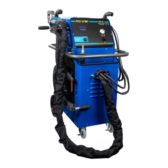
- Page 1 PHS-101 HYBRID SPOT WELDER Instruction Manual Version 1.0 All Info Copyright © Pro Spot International Inc.
-
Page 2: Contact Information
& development department, a fabrication facility and production lines for the various welders Pro Spot International exports its products worldwide, export sales are managed through our headquarter office. The company owns numerous patents for our ingenious application tools, machines, and procedures. -
Page 3: Table Of Contents
4.7.6 Battery Test 4.7.7 Restore Defaults 4.8 Checking Weld Quality 4.9 Checking Battery 4.9.1 Checking the Battery Voltage 4.9.2 Battery Alerts 4.9.3 To Remove Side Panel Covers for Service 4.9.4 Checking Battery Water Levels All Info Copyright © Pro Spot International Inc. -
Page 4: Troubleshooting
6.9 Pro Pull Dent Pulling (optional) 6.9.1 Selecting Pro Pull Weld Mode 6.9.2 Pro Pull Component Diagram 6.9.3 Pro Pull Assembly 6.9.4 Dent Pulling with Pro Pull 6.9.5 Paintless Dent Pulling with Pro Pull 7.0 Troubleshooting Notes All Info Copyright © Pro Spot International Inc. -
Page 5: Safety Information
• The safety of the welder through correct use of the equipment in accordance with the descriptions and instructions provided in this manual. 1.3 WARNINGS AND IMPORTANT NOTICES The following types of safety signs are used on the equipment and in Pro Spot’s instruction manuals: Caution. Attention! Read Instruction Manual. - Page 6 WARNING! All service and maintenance ATTENTION! Tout le service et l'entretien doivent être must be carried out by Pro Spot service effectués par personnel et soutien de service Pro personnel and service support. Risk for Spot.
-
Page 7: Warnings & Important Notices
It is not necessary to leave on at all times, but should be used when the weld cables are hot to the touch. For best results, let the welder rest when cables are too hot. Cooler weld cables result in better weld performance. All Info Copyright © Pro Spot International Inc. -
Page 8: Introduction
*SERIAL NO:______________ (The serial number is located on the back of the unit) For Parts or service contact your local distributor, Local Number: ____________________________ or in the U.S. call toll free: 1-877 PRO SPOT or 1-760-407-1414 for a customer service representative. Visit Pro Spot Online: my.prospot.com Email: info@prospot.com NOTE: You can now order parts online at: prospot.com/store/... -
Page 9: Quick Start Instructions
Air Pressure Weld Control Button Air Pressure Regulator Turn Welder On/Off To Turn On : Press Weld READY Control Button To Turn Off : Unplug Welder Press + Hold Weld Control Button All Info Copyright © Pro Spot International Inc. -
Page 10: Installation
If anything is missing, please contact your supplier. Remove all packaging material from the welder. 3.3 WELDER ASSEMBLY Insert the support arm (boom) as shown in Figure 3.1 Figure 3.1 All Info Copyright © Pro Spot International Inc. -
Page 11: Battery Installation
Place the leads (red on positive and Negative on RIGHT, Positive black on negative) on the battery on LEFT. terminals and tighten with a 1/2” socket. Do not over tighten. All Info Copyright © Pro Spot International Inc. -
Page 12: Connection Of Pneumatic Air Supply
IMPORTANT! The air must be clean and free from oil and moisture. Use a lter. IMPORTANT! L’air doit être propre sans huile et humidité, Utilisez un ltre. Air supply port Figure 3.2 All Info Copyright © Pro Spot International Inc. -
Page 13: Operation
TIME: The Timer controls the duration of the current applied during the weld cycle. The idea is to get a weld that uses higher current and shorter time to control heat buildup. WELD CYCLE CHART welder All Info Copyright © Pro Spot International Inc. -
Page 14: About Your Welder
Filtered Air 100 PSI 7 BAR (min) Back Panel WELD CABLES CONFIGURATION Tool Board 1. Two-Sided Spot Gun Cable 3. Single-Sided Weld Gun Cable 2. Two-Sided Ground Cable 4. Single-Sided Ground Cable All Info Copyright © Pro Spot International Inc. -
Page 15: Hybrid Spot Control Panel
IMPORTANT! Make sure to read the instruction manual before operating the welder. Only trained personnel should use this welder. IMPORTANT! Assurez-vous de lire le Mode d’Emploi avant d’opérer le soudeur. Seul le personnel quali é devrait utiliser ce soudeur. All Info Copyright © Pro Spot International Inc. -
Page 16: Choosing The Weld Mode
3. Lock the pressure regulator by pushing the knob into the lock position. 4.6 USER INTERFACE The PHS-101 uses a Weld Control Button to scroll through menu options on the LCD and to change settings. Rotating the Weld Control Button back and forth will move the cursor up and down on the LCD. -
Page 17: System Menu And Advanced Features
Home screen. 4.7.2 Last Weld Info The PHS-101 has an integrated current sensor that monitors the true weld current and stores the results of the last weld for diagnostic purposes. Selecting Last Weld Info will display the recorded voltage and weld current for the last weld. -
Page 18: Alert Set-Up
If this option is disabled and the Show Feedback option is set to ERR or ALL, the weld results will be displayed during the cooldown period, reverting automatically to the Home screen when the Ready LED is lit. All Info Copyright © Pro Spot International Inc. -
Page 19: Advanced Set-Up
For a healthy, fully charged battery the measured current should be ≥ 2.8kA and the measured voltage should be ≥ 2.70V. If these criteria are not met, the battery may be worn out or may have too high of an internal resistance to use in the PHS-101. 4.7.7 Restore Defaults To return all welder settings to factory defaults, use this menu option. -
Page 20: Checking Weld Quality
Expect to tear a weld nugget as the two metals are peeled apart. IMPORTANT: Use the same metal as you are welding. All Info Copyright © Pro Spot International Inc. -
Page 21: Checking Battery
12.40V 0.0A Batt2 SERVICE SERVICE Batt3 12.40V 0.0A This alert indicates that the battery voltage has fallen below 11.5V and the battery Batt4 12.40V 0.0A needs to be replaced (Fig.3). Fig. 3 All Info Copyright © Pro Spot International Inc. -
Page 22: To Remove Side Panel Covers For Service
Only slide 1 battery out at a time. Turn each fill-plug counter Do not fill more than clockwise and remove. 1/8” (2mm) above the bottom of the vent well. Overfilling will cause battery failure. 1/8” (2mm) DO NOT OVERFILL All Info Copyright © Pro Spot International Inc. -
Page 23: Ps-500 Double-Acting Spot Gun
60mm Shank Clamping Handle Figure 5.1 PS-500 Spot Gun - Component Diagram 5.1.2 Using the Double-Acting Gun Push this button to open electrodes wide. Push this button to close electrodes and weld. All Info Copyright © Pro Spot International Inc. -
Page 24: Extension Arms
(optional) PS-52 PS-302 C-Arm PS-403 (optional) Wheelhouse Arm C-X Adapter 5.2.1 Switching to extension arms Loosen the handle and pull off the C-arm... Now, insert the extension arm and tighten the handle. All Info Copyright © Pro Spot International Inc. -
Page 25: Extension Arms And Welding Electrodes
NOTE: PS-025 Welding Caps can be purchased in packages of 15 from your local distributor or online at www.prospot.com REMARQUE: PS-025 caps de soudure peuvent être achetés en paquets de 15 à partir de votre distributeur local ou en ligne à www.prospot.com All Info Copyright © Pro Spot International Inc. -
Page 26: Ps-500 Electrode Alignment
IMPORTANT! Always maintain proper electrode alignment. Not doing so may result in weak, sub- standard welds! IMPORTANT! Toujours maintenir l’alignement des électrodes appropriées. Ne pas le faire peut conduire aux aoudures faibles de qualité inférieure! All Info Copyright © Pro Spot International Inc. -
Page 27: Removing Welding Electrodes
(Fig 5.6c) Vous pouvez commander cet outil de votre Figure 5.6c: Optional Weld distributeur local ou en ligne à l’adresse: www.prospot.com Cap Removal Tool Welding Cap Piston Electrode Extension Arm Electrode Figure 5.6 Removing Welding Electrodes All Info Copyright © Pro Spot International Inc. -
Page 28: Welding Electrode Maintenance
It is also important to maintain a 6mm weld nugget diameter. Clean electrodes with a le and periodically replace welding caps as explained in Secion 5.4 “Removing Welding Electrodes”. Also Available: Pro Spot PLT-50/A Pneumatic Low Pro le Dresser sharpens your dull tips without having to remove the arm (Fig. 1) WARNING! The electrodes may be hot. -
Page 29: X-Adapter (Optional)
IMPORTANT! Ne serrez pas le collier avant de glisser l’ Électrode Rétreci dans le tube. Le collier est conçu pour empêcher l’ Électrode Rétreci de tomber du tube quand le pistolet est completement ouvert. All Info Copyright © Pro Spot International Inc. -
Page 30: Using The X-Adapter
(PS-404) (PS-411) (PS-421) PS-024 Collar Welding Cap (PS-407) 90°Electrode - Lower Pivot Axle Tapered 45°Electrode - Lower (PS-412) (PS-406) Electrode (PS-422) (PS-405) Figure 5.8 45° Arm Set Figure 5.7 90° Arm Set All Info Copyright © Pro Spot International Inc. -
Page 31: Single-Sided Welding
In the Single-Sided weld mode the following weld procedures are available for the Hybrid Spot: Single-Sided Welding (cosmetic repair only) Washer Welding Nail Welding Contact Shrinking Bolt and Nut Welding Rivet Welding Spot Hammer Dent Pulling Pro Pull Dent Removal Figure 6.2 Single-Sided applications All Info Copyright © Pro Spot International Inc. - Page 32 120 mS. For dent pulling only, start with the lowest time setting available. If less power is needed, try to seperate the ground cable further away from the weld area to create more power resistance and/or use the pointed spot hammer tip to spread out the heat zone. All Info Copyright © Pro Spot International Inc.
-
Page 33: Single-Sided Spot Welding
4. Prepare the surface area by removing paint and primer. 5. Ground the work area (refer to section 6.1 “Single-Sided Welding Overview”) 6. Position Single-Sided gun over work area and push the trigger to weld. 7. Repeat as needed. All Info Copyright © Pro Spot International Inc. -
Page 34: Nut Welding
ASTUCE: noix de di èrentes tailles sont disponibles chez votre distributeur Figure 6.15 local Spot Pro ou sur le web à la boutique Pro Spot en ligne. Nuts are held in place during welding with a shrinking electrode. 1. Select Weld Power to Low (200-250ms) 2. -
Page 35: Moulding Clip Rivet Welding
ASTUCE: Vous pouvez acheter un marteau glissant avec crochet de votre Figure 6.24 distributeur locale Pro Spot ou sur le web à la boutique Pro Spot en ligne. Washers are held in place during welding with magnetic adapter electrode. 1. Select Weld Power to Low (175ms) 2. -
Page 36: Contact Shrinking
4. Ground the working area (refer to section 6.1 “Single-Sided Welding Overview”). 5. Position the contact shrink electrode over the high spot, apply some pressure and push the trigger to weld. 6. Repeat as needed. All Info Copyright © Pro Spot International Inc. -
Page 37: Pro Pull Dent Pulling (Optional)
1.75"(44mm) x 1"(25mm) Electrode PP-10-03 Block window size: N-38 0.75" (19mm) dia. PP-10-01 CLP-75 Removable weld shaft. The weld current is transferred through the shaft and NO CABLE is required to transfer the current All Info Copyright © Pro Spot International Inc. -
Page 38: Pro Pull Assembly
6.9.4 Dent Pulling with Pro Pull Aim, position & fire! Pull dent with Auto Twist gun to release tip. Blocking. 6.9.5 Paintless Dent Pulling With Pro Pull Glue Adapter for Paintless Dent Removal All Info Copyright © Pro Spot International Inc. -
Page 39: Troubleshooting
3. Visually inspect the contactors to see if any of them appear to be stuck closed. If any contactor appears stuck, please contact Pro Spot technical support for further instructions. If no contactor is stuck, simply turning the welder back on will clear the warning and allow welding to resume. -
Page 40: Notes
NOTES All Info Copyright © Pro Spot International Inc. - Page 41 NOTES All Info Copyright © Pro Spot International Inc.
- Page 42 NOTES All Info Copyright © Pro Spot International Inc.
- Page 43 NOTES All Info Copyright © Pro Spot International Inc.
- Page 44 Pro Spot International, Inc. 5932 Sea Otter Place Carlsbad, CA 92010 Toll Free: (877) PRO SPOT Phone: (760) 407-1414 Fax: (760) 407-1421 E-mail: info@prospot.com Web: www.prospot.com Copyright © Pro Spot International, Inc. 2013...
Need help?
Do you have a question about the PHS-101 and is the answer not in the manual?
Questions and answers