
Subscribe to Our Youtube Channel
Related Manuals for Pro Spot PR-205


Summary of Contents for Pro Spot PR-205
- Page 1 PR-205 SYNERGIC MIG/MAG WELDER Instruction Manual Version 1.0 All Info Copyright © Pro Spot International Inc.
-
Page 2: Contact Information
& development department, a fabrication facility and production lines for the various welders Pro Spot International exports its products worldwide, export sales are managed through our headquarter office. The company owns numerous patents for our ingenious application tools, machines, and procedures. -
Page 3: Table Of Contents
6.1.6 MOG Welding (No Gas/Flux Core) 6.1.7 MIG/MAG Welding 6.2 MIG/MAG And No Gas Manual Welding 6.3 Automatic MIG/MAG/MOG Welding 6.4 Aluminum Welding 7.0 PROTECTION GASES GUIDE 8.0 WELDING HINTS AND MAINTENANCE 9.0 TROUBLESHOOTING NOTES All Info Copyright © Pro Spot International Inc. -
Page 4: Safety Information
• Do not weld on containers that may have held combustibles. • Always check welding area to make sure it is free of sparks, slag, or glowing metal and flames. • The work area must have a fireproof floor. All Info Copyright © Pro Spot International Inc. -
Page 5: Electric Shock
Cylinders should be secured by a chain at all times. The cylinder cap should be on all cylinders when not in use. • These welders use only inert or non-flammable gases for welding. It is important to choose the appropriate gas for the type of welding being performed. All Info Copyright © Pro Spot International Inc. -
Page 6: Installation Recommendations
In any case, the connection of the yellow/green wire to the PE terminal must be done in order that in the event of tearing of the power supply cable from the plug, the yellow/green wire should be the last one to be disconnected. All Info Copyright © Pro Spot International Inc. -
Page 7: Safety Instructions
Uo : 10-12V MIG/MAG - 38V MMA Current Output Range : 25-170 MIG/MAG - 5-170 MMA Duty Cycle : 25% 170A MIG/MAG - 25% 170A MMA 100% 85A MIG/MAG - 100% 85A MMA All Info Copyright © Pro Spot International Inc. -
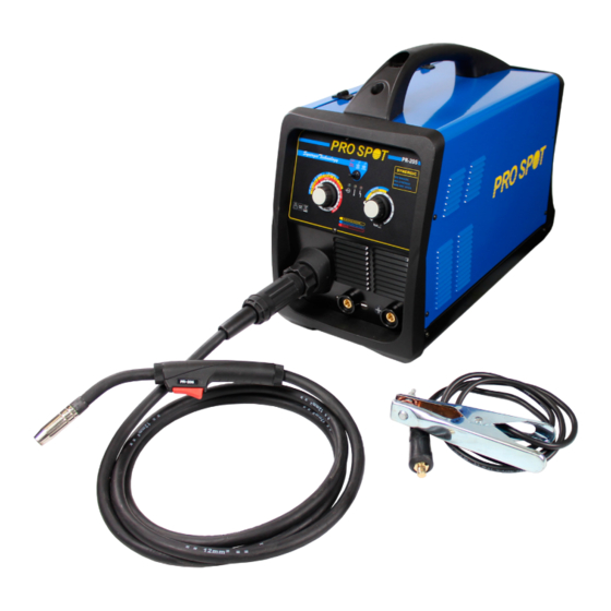
Page 8: Pr-205 Basics
Stick Welding The PR-205 can weld electrodes up to a diameter of 4.0mm. The welding current is adjustable thru the dial on the front panel MIG (GMAW and FCAW) Welding with Gas and without Gas This welder can weld in manual mode, allowing the operator to adjust the wire speed and the welding voltage and in automatic mode(synergic) by automatically associating a wire speed range to a voltage range. - Page 9 16. Burn Back Time Regulation Dial (B.B.T.) 17. Polarity Change Terminals for the Socket: • positive polarity for MIG/MAG Welding • negative polarity for No Gas/MOG Welding 18.Feed Motor Protection Fuse Figure 3 All Info Copyright © Pro Spot International Inc.
-
Page 10: Stick Welding (Mma)
If necessary, straighten or trim them before inserting it in the wire input guide (C). Insert the wire on the lower roll (D) and in the torch liner. Figure 5 All Info Copyright © Pro Spot International Inc. -
Page 11: Replacing The Wire Liner
• The Teflon wire liners are used for the welding of Aluminum, as they allow a smooth feeding of the wire. Color BLUE YELLOW Diameter Ø 0.6-0.9 Ø 1.0-1.2 Ø 1.2-1.6 All Info Copyright © Pro Spot International Inc. -
Page 12: Gas Cylinder And Regulator Connection
(5). • To stop the welding process, release the trigger. The arc stays on for the length of time set using the BBT dial (Burn Back Time)(16). All Info Copyright © Pro Spot International Inc. -
Page 13: Automatic Mig/Mag/Mog Welding
• Use contact tips that are suitable for aluminum wire and make sure that the diameter of the contact tip hole corresponds to the wire diameter that is going to be used. All Info Copyright © Pro Spot International Inc. -
Page 14: Protection Gases Guide
If the pressure roller and the wire feed roller make contact (when the wire is in place between them), the wire feed roller must be replaced. • Check all cables periodically. They must be in good condition and not cracked. All Info Copyright © Pro Spot International Inc. -
Page 15: Troubleshooting
Increase wire speed or decrease arc voltage too high. voltage. Wrong size contact tip. Use correct size contact tip. BBT time is too long. Adjust BBT time with the potentiometer located on the spool compartment (16). All Info Copyright © Pro Spot International Inc. - Page 16 Move the torch slower. incomplete. quickly. Gas mixture incorrect. See shielding gas table. Weld deposit too thick. Torch moved over workpiece too Move the torch faster. slowly. Welding voltage too low. Increase welding voltage. All Info Copyright © Pro Spot International Inc.
-
Page 17: Notes
NOTES All Info Copyright © Pro Spot International Inc. - Page 18 NOTES All Info Copyright © Pro Spot International Inc.
- Page 19 NOTES All Info Copyright © Pro Spot International Inc.
- Page 20 Pro Spot International, Inc. 5932 Sea Otter Place Carlsbad, CA 92010 Toll Free: (877) PRO SPOT Phone: (760) 407-1414 Fax: (760) 407-1421 E-mail: info@prospot.com Web: www.prospot.com Copyright © Pro Spot International, Inc. 2013...
Need help?
Do you have a question about the PR-205 and is the answer not in the manual?
Questions and answers