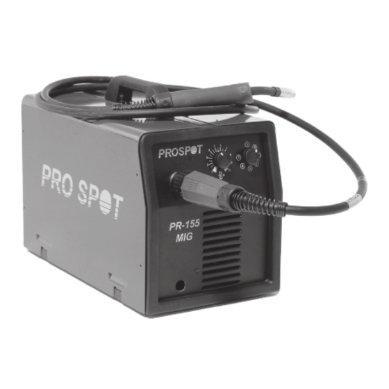
Table of Contents
Advertisement
Quick Links
Advertisement
Table of Contents

Summary of Contents for Pro Spot PR-155
- Page 1 1999-09 PR-155 Instruction Manual...
-
Page 2: Assembly Diagram
1 1 1 1 1 1 1 1 1 1 INSTALLATION page 3 DESCRIPTION OF THE MACHINE page 3 GENERAL DESCRIPTIONS page 3 INSTALLATION (CONT'D) page 4 WELDING page 4 MAINTENANCE AND CHECKS page 5 SAFETY PRECAUTIONS page 6 WIRING DIAGRAM page 9 ASSEMBLY DIAGRAM page 10 &... -
Page 3: Installation
INSTRUCTION MANUAL FOR WIRE WELDING MACHINES IMPORTANT: welding voltage range. READ THIS MANUAL CAREFULLY BEFORE INSTALLING, B) Setting knob USING, OR SERVICING THE WELDING MACHINE, PAYING This knob serves to adjust the welding wire speed. SPECIAL ATTENTION TO SAFETY RULES. CONTACT C) Earth cable YOUR DISTRIBUTOR IF YOU DO NOT FULLY UNDER- D) Yellow LED... -
Page 4: General Notes
The duty cycle expresses the percentage of out a plug, you must insert a main switch having a 10 minutes during which the welding machine suitable capacity in compliance with the rated speci- can run at a certain current without overheating. fications. -
Page 5: Welding Aluminium
After connecting the cables, follow the instructions given in 5.1.1 With gas protection. paragraph 5.1.1. Either 75% ARGON + 25% CO or 100% CO may be used for NOTE: For compact, well-protected welds always work from welding mild steel. left to right and from top to bottom. Connect the cables as shown in the figure 3. -
Page 6: Troubleshooting Guide
7.1 Fire INCANDESCENT SURFACES can cause serious burns. Let the unit cool before servicing. TROUBLE PROBABLE CAUSE REMEDY Periodically remove any dust or foreign matter that may have The welding machine Line fuse blown Replace line fuse deposited on the transformer or diodes; to do so, use a jet of supplies limited current Burnt out diode or diodes Replace... -
Page 7: Pressure Regulators
Never lubricate cylinder valves with oil or grease. Wear helmet with safety goggles and glasses with side Do not put the cylinder in electrical contact with the arc. shields underneath, appropriate filter lenses or plates (pro- Do not expose cylinders to excessive heat, sparks, molten tected by clear cover glass). - Page 8 Disconnect power supply cable from mains before replacing cables or before removing unit covers. Do not use the unit without protection covers. Always replace any damaged parts of the unit, with original material. Never disconnect unit safety devices. Make sure that the power supply line is equipped with an efficient earth plug.
- Page 9 WIRING DIAGRAM COLOUR CODE Black Grey White Green Violet Yellow Blue Brown Orange Pink Pink-Black Grey-Violet White-Violet White-Black Grey-Blue White-Red Grey-Red White-Blue Black-Blue 9 9 9 9 9...
- Page 10 P o s . P o s . DESCRIPTION DESCRIPTION P o s . P o s . P o s . DESCRIPTION DESCRIPTION DESCRIPTION KNOB KNOB FRAME CLOSING HANDLE HINGED SIDE PANEL DRIVE ROLL WIRE FEED MOTOR FRONT PANEL RING SPRING REEL OUTER SUPPORT...


Need help?
Do you have a question about the PR-155 and is the answer not in the manual?
Questions and answers