Table of Contents
Advertisement
Advertisement
Table of Contents

Related Manuals for Pro Spot PR-8


Summary of Contents for Pro Spot PR-8
- Page 1 2000-08 PR-8 Instruction Manual - approved...
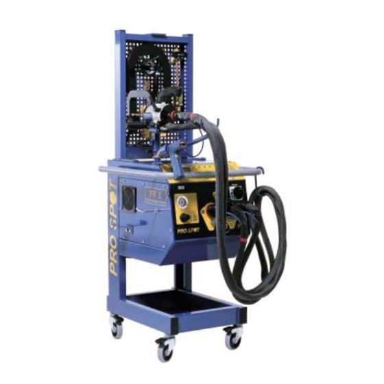
- Page 2 Read this instruction book to appreciate how versatile the Pro Spot PR-8 is. The photographs and drawings in this manual are merely illustrative and do not necessarily represent the actual appearance of equipment available.
-
Page 3: Table Of Contents
Contents Pro Spot PR-8 A. Safety Warnings, important notes and information Safety signs Placement of safety signs B. Installation Connection to the power unit Maintenance C. Function selection C1 Operating mode C2 Control pushbuttons (modes 1-5) C3 Control pushbuttons (mode 6), automatic program D. -
Page 4: Safety
A. Safety Pro Spot PR-8 A1. Warnings, important notes and information Follow these safety rules to ensure safety for the operator and other persons. In addition to the safety signs shown on page 5, the following warnings and important notes will be found elsewhere in these instructions. -
Page 5: A2 Safety Signs
A. Safety Pro Spot PR-8 A2. Safety signs Blue with white symbol. Directive - Prescribes a specific obligation Yellow with black symbol. Warning - Warning for danger. Undamaged safety signs must always be positioned at the places indicated. If any sign is damaged or missing, the user must ensure that it is immediately replaced by a new sign. -
Page 6: A3 Placement Of Safety Signs
A. Safety Pro Spot PR-8 A3. Placement of safety signs - 5 - GB/US/2000-08 PRO SPOT... -
Page 7: Installation
The equipment requires a compressed air supply at 6-8 bar. This must be clean, oil-free and moisture-free air. Connect the Pro Spot PR-8 to the compressed air system via the connection on the rear panel of the machine, using a standard compressed air connector. -
Page 8: Function Selection C1 Operating Mode
C1. Operating modes Front panel 1. 2. 3. 4. 5. 6. The Pro Spot PR-8 has six operating modes, as follows: 1. Swaging (graphite arc tool) for thermal straightening of damaged bodywork. 2. Washer welding for slide-hammer tool (pulling out dents.) 3. -
Page 9: C3 Control Pushbuttons (Mode 6), Automatic Program
C. Function selection Pro Spot PR-8 C3. Control pushbuttons in Mode 6, Automatic Program Don’t forget to connect the welding cables and control cable. When using tongs, connect the air hose on the welding cable to the air supply connection on the front panel. -
Page 10: Operation
D. Operation Pro Spot PR-8 D1. Welding tools The PR-8 has two 150 mm² screened, air-cooled welding current cables, with connectors for the welding tool to be used. Select the welding tool(s) that is/are suitable for the repair work to be performed. -
Page 11: Automatic Control And Special Programs
If the machine is to powerful: Now it is possible to use AC1 (metal thickness 0.5 - 1.9 Increase the calibration value with 10 mm) or AC2 (1.0 - 3.0 mm) and let the PR-8 compensate units and test. for different metal thickness. - Page 12 D. Operation Pro Spot PR-8 D2. Mode selection (continued) The Automatic Control System. The machine monitors the resistance of the weld as the weld current builds up, stopping the current when a correct weld has been achieved. The machine generates an error signal when a defective weld has been made.
-
Page 13: D3 Fitting The Welding Device
D3. Fitting the welding device 1) Stud holder: Two sizes of stud holders are supplied with the PRO SPOT PR-8. Select the correct holder to suit the size of stud to be welded, and fit it using the brass nut supplied. - Page 14 D. Operation Pro Spot PR-8 D3. Fitting the welding device (continued) 4) The welding electrodes, the wheel, the slide-hammer electrode and the rivet holder all feature a conical shank and can be fitted on the same adapter. 5) The slide-hammer tool (for pulling out dents) is intended to be screwed directly into the welding gun handle.
-
Page 15: D4 Fitting The Earth Connection
D. Operation Pro Spot PR-8 D4. Fitting the earth connection a) For Operating Modes 1, 2 and 3 - Carefully grind an area of 7 x 4 cm and temporarily secure the earth connection to the workpiece with a clamp. -
Page 16: D5 Welding Gun With Single Electrode
D. Operation Pro Spot PR-8 D5. Welding gun with single electrode (Operating Mode 4). The use of a microprocessor in the BOSS+V4 means that the operator needs only set the required value of the current before starting to use the equipment. However, some basic welding rules need to be followed if best use is to be made of the machine: - Do not weld on the body sheet to which the earth connection is made. -
Page 17: D6 Setting The Welding Current
D. Operation Pro Spot PR-8 D6. Setting the welding current The operator can increase or decrease the welding current with the + and – pushbuttons. The display (1) shows the Operating Mode and program that you have selected. Numbers 1 to 10 represents number of diodes ON. -
Page 18: Trouble Shooting
E. Trouble shooting Pro Spot PR-8 E1. Welding problems Swaging (Operating Mode 1): Single electrode (Operating Mode 4) Nothing happens when the graphite Spot welds are not holding: - Check the earth connection and make electrode touches the body sheet:... -
Page 19: E2 Error List
E. Trouble shooting Pro Spot PR-8 E2. Error list Error message (welding) Press the V pushbutton and try again. If the 51 = Calculation error same error message recurs, stop using the 53 = Measurement error machine and call for service. -
Page 20: Technical Specification
: 5 bar (C-tong), 6 - 8 bar (X-tong) Degrees of protection : IP 23 Pro Spot PR-8 meets the following directives: ETL and C-ETL Listed Mark, Low Voltage Directive LVD(73/23/EEC), The EMC Directive (89/336/EEC), The Machinery Directive (89/392/EEC). - 19 -... -
Page 21: F2 Block Diagram
F. Technical specification Pro Spot PR-8 F2. Block diagram Protect the equipment by means of an RCD where required by local regulations. - 20 - GB/US/2000-08 PRO SPOT... -
Page 22: F3 Diagram
F. Technical specification Pro Spot PR-8 F3. Diagram Welding current The actual welding current depends on several factors: supply voltage, cable length and cable cross-sectional area are 15KA particularly important. The diagram represents the main func- 10KA tions and processes graphically. - Page 23 1-10% (0,6 seconds welding with 6-10 seconds between welds). 50 % The Pro Spot PR-8 has a intermittence factor of: 2,5% without getting a overheat. Welding current Calculated as follow. In 1 minute it’s possibly to make 8 spotwelds.
-
Page 24: Spare Parts
G. Spare parts Pro Spot PR-8 Grundsats/Basic set 5 7 8 9 x 200 x 100 x 50 x 50 Pos Part.No. Quant. Description Basic set 1392001300 Puller 1394003201 Single spot gun 1391003101 1394001113 Electrode holder 1394001108 Pencil tip holder... - Page 25 G. Spare parts Pro Spot PR-8 6 7 8 9 10 11 12 13 Pos Part.No. Quant. Description C-tong 1394025300 C-tong 1394025302 80-yoke 1394025303 330-yoke 1394001103 Electrode length 40 1394001101 Electrode length 80 1394025310 Fender Edge Kit 1394001135 Washer 1394001133...
- Page 26 G. Spare parts Pro Spot PR-8 8 9 10 11 12 Pos Part.No. Quant. Description Cables 1394010306 Cable, 150mm 3m + 1394010305 Cable, 150mm 3m - 1394010306 Cable, 240mm 2,4m + 1394010305 Cable, 240mm 2,4m - Electrodes 1394001131 Electrode length 20...
- Page 27 G. Spare parts Pro Spot PR-8 Pos Part.No. Quant. Description 1394025310 Fender Edge Kit Accessories 1394001135 Washer 1394001133 Electrode L80-S13 1394001134 Electrode L80/45°-S13 1394001132 Electrode L80/45° 1394001137 Electrodeholder 1394001136 Electrodeholder 1394001131 Electrode length 20 1394001104 Electrode -S 1394025304 Fender edge yoke...
-
Page 28: C-Tong Situations
H. C-tong Situations Pro Spot PR-8 - 27 - GB/US/2000-08 PRO SPOT... - Page 29 Pro Spot International, Inc 956 S. Andreasen Dr. #101 Escondido, CA 92029 U.S.A. 1-877 PRO SPOT (760) 489-1531 E-Mail: info@prospot.com Internet http://www.prospot.com...
Need help?
Do you have a question about the PR-8 and is the answer not in the manual?
Questions and answers