
Related Manuals for Pro Spot SP-5


Summary of Contents for Pro Spot SP-5
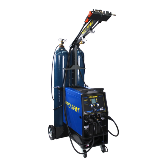
- Page 1 SP-5 SMART MIG WELDER Kurzanleitung Instruction Manual Version 2.0 All Info Copyright © Pro Spot International Inc.
- Page 2 & development department, a fabrication facility and production lines for the various welders. Pro Spot International exports its products worldwide, export sales are managed through our headquarter of ce. The company owns numerous patents for our ingenious application tools, machines, and procedures.
-
Page 3: Table Of Contents
ENGLISH ESPAÑOL NORMAS DE SEGURIDAD Ó SEGURIDAD PERSONAL PERSONAL PROTECTION PREVENCION DE LOS INCENDIOS Ó COMPATIBILIDAD ELECTROMAGNÉTICA ELECTROMAGNETIC COMPATIBILITY GASES DE PROTECCIÓN PROTECTIVE WELDING GASES Ó INSTALLATION RECOMMENDATIONS MONTAJE DE RUEDAS Y MANILLA (FIG. 2) CONEXIÓN DE LAS TORCHAS (FIG.3) INSTALACIÓN DEL SUPORTE DE LA BOMBONA MAIN SUPPLY VOLTAGE REQUIREMENTS (FIG.4) Y DEL ASTA PORTATORCHA (FIG.5) -
Page 4: Personal Protection
SAFETY INFORMATION INTRODUCTION Make sure this manual is carefully read and understood by the welder, and by the maintenance and technical workers. PERSONAL PROTECTION Welding processes of any kind can be dangerous not only to the operator but to any person situated near the equipment, if safety and operating rules are not strictly observed. -
Page 5: Electromagnetic Compatibility
other insulating materials to move cables, if necessary away from the person. • Wear dry gloves and clothing. Insulate yourself from the work piece or other parts of the welding circuit. • Make sure the main line is properly grounded. •... -
Page 6: Installation Recommendations
INSTALLATION RECOMMENDATIONS LOCATION Be sure to locate the welder according to the following guidelines: • In areas, free from moisture and dust; • Ambient temperature between 0° to 40°C; • In areas, free from oil, steam and corrosive gases; • In areas, not subjected to abnormal vibration or shock;... -
Page 7: Assembly
ASSEMBLY HANDLE AND WHEELS ASSEMBLY (FIG. 2) • Unpack the welder. • Screw the two casters (D) to the machine. • Insert the axle (A) thru the holes at the rear of the welder and slide a wheel (B) on to each end followed by the retaining washers (C). - Page 8 INTRODUCTION This manual was edited to give some indications on the operation of the welder and was thought to offer information for its practical and secure use. Its purpose is not teach welding techniques. All given suggestions are indicative and Iintended to be only guide lines. To ensure that your welder is in good conditions, inspect it carefully when you remove it from its packing having care to ascertain that the cabinet or the stocked accessories are not damaged.
- Page 9 UNIT CONTROLS FIG. 6 Mode Key Display Setup Key Prog save & recall Key Right Regulation Knob Material Key Left Regulation Knob ON/OFF Switch Negative Socket Postitive Socket Euro Connection for Torch 1 - AL Euro Connection for Torch 2 - FE/SS Euro Connection for Torch 3 - CuSi and Torch TIG Accessories Compartment Torches Holding Bar...
- Page 10 CONTROL INTERFACE Figure 7 Mode Key • welding process selection • return to the main screen after parameters setting Graphic Display Setup Key setting of the secondary parameters in all welding processes 3.1 Tig Function 2stroke/4stroke, Slope Up (0-10 sec), Slope Down (0-20 sec), crater Filler value in 4stroke function only, Post Gas Time 0-5 sec 3.2 Mig/Mag Function Synergy: OFF /ON/PULSED, 2Stroke/4Stroke/Spot welding, Spot Time, Motor Slope, BBT, Electronic Inductance,...
-
Page 11: Connection And Preparationf
BASIC SETUP MENU To enter the Basic Setup Menu power the unit on; while the display views the unit logo, press the Setup Key - 3 -. Use the Right Regulation Knob - 5 - to adjust the modifiable parameters: MAX LINE CURRENT - L/H Setting of the maximum current that the unit may absorb by the input power supply according to the branch circuit capability. -
Page 12: Connection And Setup
CONNECTION AND SETUP FOR TIG WELDING • Connect the earth cable to the Positive output terminal on the front of the unit. • Connect the Tig Torch to the Negative output terminal on the front of the unit. • Connect the torch trigger plug and the gas hose to the corresponding connectors on the front panel (use only Argon) •... -
Page 13: Tig Welding In Normal Mode
TIG WELDING IN NORMAL MODE MATERIAL KEY - Press the Material Key and turn the Right regulation Knob - 5 - to select the working “NORMAL”. Go back to the main screen by pressing the Mode Key - 1 -. Figure 12 Graphic Display - •... - Page 14 Graphic Display - • Real Current • TIG Mode • Set Current • Pulsation Frequency. Figure 16 Use the Mode Key - 1 - to go back to the TIG main screen after desired parameters are adjusted. Tig Function Setup Key - Follow instructions at paragraph 6.0 - Connection and Setup for TIG Welding In PULSED Mode use the Regulation Knobs - 7.2 - and - 5 - to adjust the following parameters on the main screen:...
-
Page 15: Mig/Mag Welding Setup
MIG/MAG WELDING SETUP MODE Key - Press the Mode Key till the MIG/MAG Welding Screen is viewed on the display. Unit can be set for working in three different modes: Normal MIG Synergic MIG Pulsed MIG. Follow carefully the following instructions paying particular attention to the pictures. - Page 16 IND.: regulation of the electronic inductance value (0-11) Low Value = more spatters High Value = less spatters POST GAS: Regulation of the gas outflow time at the end of welding (0 – 5 Sec.) Percentage of reduction of the welding parameter during the crater Filler (30 - 100%) (only 4T) Duration of the Welding Current Slope Down changes according to the set crater filler percentag.
-
Page 17: Getting Ready For Mig/Mag Welding
GETTING READY FOR MIG/MAG WELDING TORCH CONNECTION • Plug the torch hose into the socket on the front of the welder having care to not damage the contacts and secure by hand screwing in the threaded connection. WIRE LOADING Ensure the gas and electrical supplies are disconnected. Be- fore proceeding, remove the nozzle and the contact tip from the torch. -
Page 18: Gas Cylinder And Regulatorc
REPLACING THE WIRE LINER • Disconnect the torch from the machine. • Place it on a flat surface and carefully remove the brass nut (1). • Pull the liner out of the hose. • Install the new liner and mount the brass nut (1) again. -
Page 19: Mig/Mag - Syn Off Welding
tip hole corresponds to the wire diameter that is going to be used. To obtain a high duty cycle without wire feeding problems it is advisable to install the gas diffuser, the contact tip with 8mm thread and the nozzle. For easy welding of Aluminium and good quality welding results it is advisable to work in Pulsed Mode. -
Page 20: Mig/Mag - Syn On/Pulsed Welding
MIG/MAG - SYN ON/PULSED WELDING With the torch connected, the wire installed and the gas connection made, earth cable to the Negative output terminal on the front of the unit. Mode Key - Press the Mode Key till the MIG/MAG Welding Screen is viewed on the display. -
Page 21: Quick Start Chart Form
QUICK START CHART FOR MIG/MAG WELDING Save & Recall of operator’s Setups SYNERGY OFF SYNERGY ON PULSED MODE :2T/4T/Spot Spot Time : (0-10 sec) Slope : (0-1.50 sec) BBT: (1-10) IND.: (0-11) POST GAS: (0 – 5 Sec.) CRATER FILL (30-100%) •... -
Page 22: Synergic Programs List
SYNERGIC PROGRAMS LIST In “Synergic ON” and “pulsed” Mode use the Material Key - 6.2.2 - to enter the synergic programs list. Synergic ON Material Diameter ArCO2 ArCO2 ArCO2 CrNi ArCO2 CrNi ArCO2 CuSi CuSi MSIP1 ArCO2 Pulsed AlMg Normal AlMg Normal AlMg... - Page 23 TROUBLESHOOTING This chart will assist you in resolving common problems you may encounter. These are not all the possible solutions. POSSIBLE CAUSE PROBLEM POSSIBLE SOLUTION No “life” from welder Check for proper input cable connection Input cable or plug malfunction. Wrong size fuse.
- Page 24 Poor quality welds Nozzle clogged Clean or replace nozzle Torch held too far from the Hold the torch at the right distance workpiece Insufficient gas at weld area Check that the gas is not being blown away by drafts and if so move to more sheltered weld area.
-
Page 26: Normas De Seguridad
NORMAS DE SEGURIDAD INTRODUCCIÓN Comprobar que este manual sea leído y entendido tanto por el operador como por el personal técnico encargado del mantenimiento. SEGURIDAD PERSONAL Si las normas de seguridad y de uso no son observadas atentamente, las operaciones de soldadura pueden resultar peligrosas no solamente para el operador, sino también para las personas que se encuentran cerca del lugar de soldadura. -
Page 27: Compatibilidad Electromagnética
• En cada lugar de trabajo debe encontrarse presente una persona capacitada para los cuidados de Emergencia. • En caso de presunta electrocución y si la persona afectada está inconciente, no tocarla si se en- cuentra aún en contacto con unos controles. Cortar la alimentación de la máquina y proceder a las prácticas de Primeros Auxilios. -
Page 28: Montaje De Ruedas Y Manilla (Fig. 2)
INSTALACIÓN MONTAJE DE RUEDAS Y MANILLA (FIG. 2) • Desembalar la soldadora. • Ajustar las dos ruedas giratorias anteriores (D). • Introducir el eje (A) de las ruedas posteriores (B) en el sitio correspondiente, montar las ruedas y afian- zarlas con los anillos adjuntos (C). •... -
Page 29: Recomendaciones Para La Instalación
RECOMENDACIONES PARA LA INSTALACIÓN COLOCACIÓN Seguir las siguientes instrucciones generales para la correcta colocación de la soldadora: • En lugares libres de polvo y humedad; • A temperaturas incluidas entre 0° y 40°C; • En lugares protegidos contra aceite, vapor y gases corrosivos; •... - Page 30 INTRODUCCIÓN Este manual se redacta para dar indicaciones sobre el funcionamiento de la soldadora, ofrecien- do información que asegure su uso seguro. Su finalidad no es proporcionar instrucciones sobre técnicas de soldadura. Todas las sugerencias proporcionadas son indicativas y deben meramente interpretarse como orientaciones guía.
-
Page 31: Dispositivos Del Equipo
DISPOSITIVOS DEL EQUIPO Figura 6 Botón Mode Display Grafico Botón Setup Botón Prog save & recall Mando de regulación DER Botón Material Mando de regulación IZQ Interruptor ON/OFF Toma negativa Toma positiva Conexión Euro Torcha 1 - AL Conexión Euro Torcha 2 - FE/SS Conexión Euro Torcha 3 - CuSi y Torcha TIG Compartimiento accessorios Barra portatorcha... -
Page 32: Interfaz De Control
INTERFAZ DE CONTROL Figura 7 Botón Mode • selección del proceso de soldadura • retorno a la página principal tras haber modificado los parámetros Pantalla gráfica Botón Setup configuración de los parámetros secundarios en los distintos procesos de soldadura 3.1 Función Tig 2T/4T, Tiempo Rampa de subida (0-10 seg),Tiempo Rampa de bajada (0-20 seg), corriente nal (crater Filler) sólo en función 4T ,Tiempo Post Gas 0-5 seg 3.2 Función Mig/Mag... -
Page 33: Menú De Configuración Básica
MENÚ DE CONFIGURACIÓN BÁSICA Para acceder al menú de configuración básica, encienda el generador; mientras la pantalla muestra el logotipo del generador, presione el botón Setup - 3 -. Utilice el Mando de Regulación Der. - 5 - para configurar los parámetros modificables. MAX LINE CURRENT - L/H A través de esta opción es posible ajustar el límite de la corriente absorbida por la máquina en base a la corriente máxima que puede suministrar la línea de alimen-... -
Page 34: Conexión Y Preparación
CONEXIÓN Y PREPARACIÓN PARA SOLDADURA TIG • Conecte el cable de la pinza de masa a la toma POSITIVA del generador • Conecte la Antorcha TIG a la toma NEGATIVA del generador • Conecte el conector del botón de la antorcha y el tubo de gas a las correspondientes tomas (utilizar sólo Argón) •... -
Page 35: Soldadura Tig - Modo Normal
SOLDADURA TIG - MODO NORMAL BOTÓN MATERIAL - Pulse el botón Material, coloque el mando DER en la posición indicada con la palabra NORMAL. Vuelva a la página Tig presionando el botón Mode Figura 12 Pantalla gráfica - • Modo TIG •... -
Page 36: Cuadro Esquemático De Regulaciones
Pantalla gráfica - 2 - • Corriente real • Modo TIG • Corriente configurada • Frecuencia de Pulsación Figura 16 Para volver a la página Tig presione el botón Setup Tig - 3.1 - Siga las instrucciones del apartado 6.0 - Conexión y preparación para soldadura TIG. En modo TIG PULSED, desde la página principal, utilizando los mandos - 7.2 - y - 5 - situados en la parte frontal, se pueden regular los parámetros siguientes:... -
Page 37: Preparación Para La Soldadura Mig/Mag
PREPARACIÓN PARA LA SOLDADURA MIG/MAG Botón Mode - 1 - Seleccione el proceso de soldadura MIG/MAG por medio del botón MODE El generador puede utilizarse en 3 modos de soldadura Mig: Mig normal Mig sinérgico Mig Pulsado. Para comprender mejor las operaciones que a continuación se describen le recomendamos pre- star mucha atención a las imágenes que las acom- pañan y a sus correspondientes explicaciones. - Page 38 IND. regula el valor de la inductancia electrónica (0-11) Valor Bajo = Más salpicaduras Valor Alto = Menos salpicaduras POST GAS Configura el tiempo de salida del gas al final de la soldadura (0 – 5 Seg.) Porcentaje de reducción del parámetro de soldadura en la fase de cráter (30 - 100%) La duración de la rampa de bajada de la corriente de soldadura varia en proporción al porcentaje de crater fill configurado.
-
Page 39: Conexión Y Preparación A La
CONEXIÓN Y PREPARACIÓN A LA SOLDADURA MIG/MAG CONEXIÓN DE LA TORCHA • Introducir el bloque de latón terminal de la antorcha a la toma de corriente Euro situada en la parte frontal de la máquina, prestando atención a no estropear los contactos; luego atornil- lar la abrazadera de bloqueo de la antorcha. - Page 40 SUSTITUCIÓN DE LA VAINA GUÍA-ALAMBRE • Desconectar la antorcha de la máquina. • Colocarla en una superficie plana y, prestando atención, retirar la tuerca de latón (1). • Sacar la vaina (2). • Introducir la nueva vaina y volver a armar la tuerca de latón (1).
- Page 41 • Para garantizar un ciclo de trabajo elevado sin problemas de avance del alambre, es recomendable instalar el difusor de gas, la punta guía-hilo de rosca de 8 mm y la boquilla: Comprobar que la longitud del cable no supere los 3m; se desaconsejan longitudes superiores Montar la vaina de teflón para aluminio (seguir las instrucciones para la sustitución de la vaina que se describen en el párrafo: “Sustitución de la vaina guía-alambre”).
- Page 42 REGULACIONES SOLDADURA MAG - SYN ON/PULSED Después de efectuar las operaciones de conexión de la antorcha, carga del hilo y conexión del gas, conecte el cable de masa a la toma negativa del generador Botón Mode - Seleccione el proceso de soldadura MAG por medio del botón MODE Botón MIG/MAG Setup - En modo Mag, al pulsar el botón...
- Page 43 CUADRO ESQUEMÁTICO DE REGULACIONES MAG Este botón guarda y recupera los puntos configurables por el operador SYNERGY OFF SYNERGY ON PULSED MODE :2T/4T/Spot Spot Time : (0-10 seg) Slope : (0-1.50 seg) BBT: (1-10) IND.: (0-11) POST GAS: (0 – 5 Seg.) CRATER FILL (30-100%) •...
- Page 44 LISTA PROGRAMAS SINÉRGICOS Lista de los programas sinérgicos que se pueden utilizar con el botón material - 6.2.2 - en modalidad MIG / MAG pulsado y sinérgica. Sinergia ON Material Diametro ArCO2 ArCO2 ArCO2 CrNi ArCO2 CrNi ArCO2 CuSi CuSi MSIP1 ArCO2 Pulsos...
- Page 45 • Atención: no soplar aire en la tarjeta o en otros componentes electrónicos. • Durante la normal utilización de la soldadora, el rodillo arrastra-alambre se desgasta. Aplicando la presión correcta, el rodillo aprieta-alambre debe arrastrar el alambre sin patinar. Si el rodillo arrastra-alambre y el rodillo aprieta-alambre se tocan con el alambre introducido, el rodillo arra- stra-alambre se debe sustituir.
- Page 46 Punta de dimensiones equivocadas. Utilizar una punta de las dimensiones correctas. La pinza y/o el cable se re- Mala conexión entre cable y pinza. Apretar la conexión o sustituir el cable. calientan La tobera forma un arco con Acumulación de residuos en el Limpiar o sustituir la tobera.
- Page 48 NOTES...
- Page 49 NOTES...
- Page 50 NOTES...
- Page 51 NOTES...
- Page 52 Pro Spot international, Inc. 5932 Sea Otter Place Carlsbad, CA 92010 Toll Free (US Only): (877) PRO SPOT Phone: (760) 407-1414 Fax: (760) 407-1421 E-mail: info@prospot.com Web: www.prospot.com All Info Copyright © Pro Spot International Inc.
Need help?
Do you have a question about the SP-5 and is the answer not in the manual?
Questions and answers