
Related Manuals for Pro Spot SP-2


Summary of Contents for Pro Spot SP-2
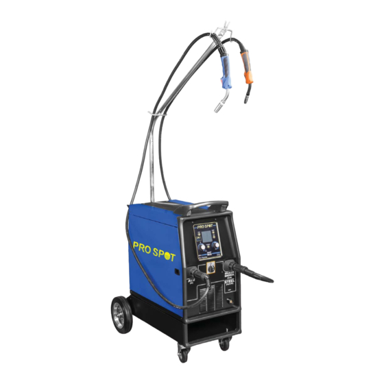
- Page 1 Resistance SP-2 Spot Welder SMART MIG WELDER Instruction Manual nstruction M v1.0a v1.0a Version 1.1 All Info Copyright © Pro Spot International Inc. All Info Copyright © Pro Spot Intern...
- Page 2 & development department, a fabrication facility and production lines for the various welders. Pro Spot International exports its products worldwide, export sales are managed through our headquarter offi ce. The company owns numerous patents for our ingenious application tools, machines, and procedures.
-
Page 3: Safety Information
SAFETY INFORMATION INTRODUCTION Make sure this manual is carefully read and understood by the welder, and by the maintenance and technical workers. PERSONAL PROTECTION Welding processes of any kind can be dangerous not only to the operator but to any person situated near the equipment, if safety and operating rules are not strictly observed. -
Page 4: Electromagnetic Compatibility
other insulating materials to move cables, if necessary away from the person. • Wear dry gloves and clothing. Insulate yourself from the work piece or other parts of the welding circuit. • Make sure the main line is properly grounded. •... -
Page 5: Installation Recommendations
INSTALLATION RECOMMENDATIONS LOCATION Be sure to locate the welder according to the following guidelines: • In areas, free from moisture and dust; • Ambient temperature between 0° to 40°C; • In areas, free from oil, steam and corrosive gases; • In areas, not subjected to abnormal vibration or shock;... -
Page 6: Handle And Wheels Assembly (Fig. 1)
ASSEMBLY HANDLE AND WHEELS ASSEMBLY (FIG. 1) • Unpack the welder. • Screw the two casters (D) to the machine. • Insert the axle (A) thru the holes at the rear of the welder and slide a wheel (B) on to each end followed by the retaining washers (C). -
Page 7: Gas Cylinder
INTRODUCTION This manual was edited to give some indications on the operation of the welder and was thought to offer information for its practical and secure use. Its purpose is not teach welding techniques. All given suggestions are indicative and Iintended to be only guide lines. To ensure that your welder is in good conditions, inspect it carefully when you remove it from its packing having care to ascertain that the cabinet or the stocked accessories are not damaged. -
Page 8: Unit Controls
UNIT CONTROLS Mode Key Display Setup Key Prog save & recall Key Right Regulation Knob Material Key Left Regulation Knob ON/OFF Switch ON/OFF Switch Negative Socket Negative Socket Negative Socket Euro Connection for Torch 1 - AL Eu u ro Connection for Torch 1 - AL Euro Connection for Torch 2 - CuSi Eu u ro Connection for Torch 2 - CuSi Accessories Compartment... -
Page 9: Control Interface
CONTROL INTERFACE Figure 6 Mode Key • return to the main screen after parameters setting Graphic Display Setup Key setting of the secondary parameters in all welding processes Synergy: OFF /ON/PULSED, 2Stroke/4Stroke/Spot welding, Spot Time, Motor Slope, BBT, Electronic Inductance, Post Gas, Crater Filler Prog save &... -
Page 10: Mig/Mag Welding Setup
VRD - ON/OFF Selection of the Voltage Reduction Device ON or OFF. As default this is OFF. In arc mode, the unit powers off at the end of welding to automatically restart when the electrode gets in touch with the workpiece. D.M. - Page 11 Slope: regulation of the time the wire needs from the striking speed to the welding speed (0-1.50 sec) BBT: regulation of the lenght of the wire protruding from the torch at the end of welding (1-10) IND.: regulation of the electronic inductance value (0-11) Low Value = more spatters High Value = less spatters POST GAS: Regulation of the gas outflow time at the end of welding (0 –...
-
Page 12: Torch Connection
GETTING READY FOR MIG/MAG WELDING TORCH CONNECTION • Plug the torch hose into the socket on the front of the welder having care to not damage the contacts and secure by hand screwing in the threaded connection. WIRE LOADING Ensure the gas and electrical supplies are disconnected. Be- fore proceeding, remove the nozzle and the contact tip from the torch. -
Page 13: Replacing The Wire Liner
REPLACING THE WIRE LINER • Disconnect the torch from the machine. • Place it on a flat surface and carefully remove the brass nut (1). • Pull the liner out of the hose. • Install the new liner and mount the brass nut (1) again. - Page 14 tip hole corresponds to the wire diameter that is going to be used. To obtain a high duty cycle without wire feeding problems it is advisable to install the gas diffuser, the contact tip with 8mm thread and the nozzle. For easy welding of Aluminium and good quality welding results it is advisable to work in Pulsed Mode.
- Page 15 MIG/MAG Function Setup Key - Press the Setup Key - 3.2 - in MIG/MAG Mode to access the parameters’ setup screen . Use the Right Regulation Knob to select the “Synergy ON” Mode for normal welding or “PULSED” Mode for pulsed welding. Use the Mode Key - 1 - to go back to the MIG/ MAG main screen.
- Page 16 QUICK START CHART FOR MIG/MAG WELDING Save & Recall of operator’s Setups SYNERGY OFF SYNERGY ON PULSED MODE :2T/4T/Spot Spot Time : (0-10 sec) Slope : (0-1.50 sec) BBT: (1-10) IND.: (0-11) POST GAS: (0 – 5 Sec.) CRATER FILL (30-100%) •...
-
Page 17: Protection Gases Guide
SYNERGIC PROGRAMS LIST In “Synergic ON” and “pulsed” Mode use the Material Key - 6.2 - to enter the synergic programs list. Synergic ON Material Diameter ArCO2 ArCO2 ArCO2 CrNi ArCO2 CrNi ArCO2 CuSi Ar 0.8 CuSi Ar 1.0 MSIP1 ArCO2 Pulsed AlMg... -
Page 18: Troubleshooting
TROUBLESHOOTING This chart will assist you in resolving common problems you may encounter. These are not all the possible solutions. POSSIBLE CAUSE PROBLEM POSSIBLE SOLUTION No “life” from welder Check for proper input cable connection Input cable or plug malfunction. Check fuse and replace as necessary Wrong size fuse. - Page 19 Nozzle clogged Poor quality welds Clean or replace nozzle Torch held too far from the Hold the torch at the right distance workpiece Insufficient gas at weld area Check that the gas is not being blown away by drafts and if so move to more sheltered weld area.
- Page 20 Pro Spot international, Inc. 5932 Sea Otter Place Carlsbad, CA 92010 Toll Free (US Only): (877) PRO SPOT Phone: (760) 407-1414 Fax: (760) 407-1421 E-mail: info@prospot.com Web: www.prospot.com All Info Copyright © Pro Spot International Inc.
Need help?
Do you have a question about the SP-2 and is the answer not in the manual?
Questions and answers