
Related Manuals for Pro Spot Exocut PR-30P


Summary of Contents for Pro Spot Exocut PR-30P
- Page 1 PR-30P Exocut™ Plasma Cutting and Gouging System Operator Manual 86-8011 (808730) | Revision 1 Copyright © Pro Spot International, Inc. 2014...
- Page 2 Visit Pro Spot online: www.prospot.com E-mail: info@prospot.com Pro Spot is a trademark of Pro Spot International, Inc. and may be registered in the United States and other countries. All other trademarks are the property of their respective holders. © 2014 Pro Spot International, Inc.
- Page 3 & development department, a fabrication facility and production lines for the various welders. Pro Spot International exports its products worldwide, export sales are managed through our headquarter office. The company owns numerous patents for our ingenious application tools, machines, and procedures.
- Page 5 PR-30P Exocut Operator Manual 86-8011 Revision 1 English August 2014 Pro Spot International, Inc. Carlsbad, CA 92010 USA...
- Page 7 Safety information Before operating this system, read the separate Safety and Compliance Manual (86-8015) included with your product for important safety information.
-
Page 9: Table Of Contents
Transfer of rights ..................................SC-16 1 Specifications ..........................17 Safety information ..................................17 System description ..................................17 Power supply dimensions ................................18 System weights ..................................... 18 Pro Spot system ratings ................................19 Torch dimensions ..................................20 PR-30P Exocut Operator Manual 86-8011... - Page 10 Contents Torch weight ....................................20 Cutting specifications .................................. 20 Symbols and marks ..................................21 Noise levels .................................... 22 IEC symbols ................................... 22 2 Power Supply Setup ........................23 Unpack the plasma system ................................ 23 Claims ...................................... 23 System contents ................................... 24 Position the plasma system ................................
- Page 11 Contents Attach the ground clamp ..............................46 Power ON the system ................................. 46 Adjust the gas pressure and output current ........................46 Operating the system on a 120 V, 15 A circuit ..................... 47 Operating the system on a 120 V, 20 A circuit ..................... 47 Operating the system on a 240 V, 20 A circuit .....................
- Page 12 Contents ThinCut consumables ................................79 Gouging consumables ................................ 79 Accessory parts .................................... 80 PR-30P Exocut labels ................................. 80 PR-30P Exocut Operator Manual 86-8011...
-
Page 13: Electromagnetic Compatibility (Emc
Electromagnetic Compatibility (EMC) Installation and use Methods of reducing emissions The user is responsible for installing and using the plasma Mains supply equipment according to the manufacturer’s instructions. Cutting equipment must be connected to the mains If electromagnetic disturbances are detected then it shall supply according to the manufacturer’s recommendations. -
Page 14: Maintenance Of Cutting Equipment
Electromagnetic Compatibility (EMC) Maintenance of cutting equipment Earthing of the workpiece Where the workpiece is not bonded to earth for electrical The cutting equipment must be routinely maintained safety, nor connected to earth because of its size and according to the manufacturer’s recommendations. All position, for example, ship’s hull, building steel work, or access and service doors and covers should be closed vehicle frame, a connection bonding the workpiece to... -
Page 15: Warranty
Pro Spot system. Any damage conditions of quality or of merchantability or fitness for a or injury caused by the use of other than genuine Pro Spot particular purpose or against infringement. The foregoing parts may not be covered by the Pro Spot warranty, and shall constitute the sole and exclusive remedy for any will constitute misuse of the Pro Spot Product. -
Page 16: Patent Indemnity
(whether in court, be developed by Pro Spot, Pro Spot will have the right to arbitration, regulatory proceeding or otherwise) defend or settle, at its own expense, any suit or... -
Page 17: Specifications
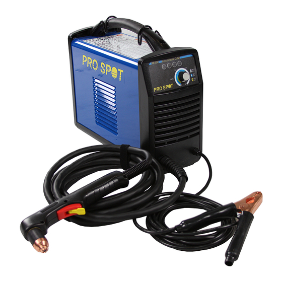
Section 1 Specifications Safety information Before operating any Pro Spot equipment, read the separate Safety and Compliance Manual included with your product for important safety information. System description The PR-30P Exocut is a highly portable, 30 A, handheld plasma cutting system appropriate for a wide range of applications. -
Page 18: Power Supply Dimensions
1 – Specifications 1 region-specific air fitting: Industrial interchange quick-disconnect nipple with 1/4 NPT threads External regulator for gouging Carrying strap Operator Manual Safety and Compliance Manual For details on how to select the right set of consumables for a given cutting job, see Choose the consumables on page 32. -
Page 19: Pro Spot System Ratings
1 – Specifications Pro Spot system ratings Rated open circuit voltage (U 256 VDC Rated output current (I 15 A to 30 A Rated output voltage (U ) at U = 120 VAC 83 VDC Rated output voltage (U ) at 125 VDC = 200 –... -
Page 20: Torch Dimensions
1 – Specifications Torch dimensions 218 mm (8.6 inch) 41 mm (1.6 inch) 75° 84 mm (3.3 inch) 48 mm (1.9 inch) 25 mm (1.0 inch) Torch weight Hand torch with general-purpose (standard) consumables only 0.3 kg (0.75 pounds) Hand torch with general-purpose (standard) consumables and 4.6 m (15 foot) lead (with 1.1 kg (2.35 pounds) strain relief) Cutting specifications... -
Page 21: Symbols And Marks
1 – Specifications Symbols and marks Your product may have one or more of the following markings on or near the data plate. Due to differences and conflicts in national regulations, not all marks are applied to every version of a product. S mark The S mark indicates that the power supply and torch are suitable for operations carried out in environments with increased hazard of electrical shock according to IEC 60974-1. -
Page 22: Noise Levels
1 – Specifications Noise levels This plasma system may exceed acceptable noise levels as defined by national and local codes. Always wear proper ear protection when cutting. Any noise measurements taken depend on the specific environment in which the system is used. Refer to Noise can damage hearing in the Safety and Compliance Manual included with your system. -
Page 23: Power Supply Setup
Claims for damage during shipment – If your unit was damaged during shipment, file a claim with the carrier. You can contact Pro Spot for a copy of the bill of lading. If you need additional assistance, call the Pro Spot office listed in the front of this manual. -
Page 24: System Contents
2 – Power Supply Setup System contents The following illustration shows the components typically included with all system configurations. Additional components – such as setup instructions, a carrying case and protective glasses and gloves – may also be included with your system, depending on the configuration you ordered. -
Page 25: Position The Plasma System
2 – Power Supply Setup Position the plasma system Position the plasma system near an appropriate power receptacle. The system has a 3.0 m (10 foot) power cord. Allow at least 0.25 m (10 inches) of space around the power supply for proper ventilation. ... -
Page 26: Voltage Configurations
2 – Power Supply Setup Voltage configurations The system automatically adjusts for proper operation at the current input voltage without requiring you to perform any switching or rewiring. However, you must set the amperage adjustment knob to an appropriate output current and verify that an appropriate set of consumables is properly installed in the torch. -
Page 27: Requirements For Grounding
2 – Power Supply Setup Requirements for grounding Properly ground the system as follows to ensure personal safety, proper operation, and to reduce electromagnetic interference (EMI): The system must be grounded through the power cord according to national and local electrical codes. ... -
Page 28: Extension Cord Recommendations
2 – Power Supply Setup Extension cord recommendations Use an extension cord of an appropriate wire gauge for the cord length and system voltage. Use a cord that meets national and local codes. Input voltage Phase Recommended cord gauge size Length 120 VAC 4 mm... -
Page 29: Prepare The Gas Supply
2 – Power Supply Setup Prepare the gas supply The gas supply can be shop-compressed or cylinder-compressed. You must regulate the gas so that the gas reaches the filter on the power supply at 99.1 L/min at 4.7 bar (3.5 scfm at 68 psi). This system comes with a regulator that attaches to the air fitting on the back of the system. -
Page 30: Additional Gas Filtration
2 – Power Supply Setup WARNING! The air filter bowl may explode if the gas supply pressure exceeds 9.3 bar (135 psi). Additional gas filtration When site conditions introduce moisture, oil, or other contaminants into the gas line, use a three-stage coalescing filtration system. -
Page 31: Torch Setup
Section 3 Torch Setup Introduction The PR-30P Exocut includes the Pro-30T hand torch. This section explains how to set up and operate your torch. To achieve optimal consumable life and cut quality, follow the instructions in this manual. Hand torch components Handle Safety catch Shield (shown) or deflector... -
Page 32: Consumable Life
Consumables (general-purpose, ThinCut, or gouging) Pro Spot does not recommend the use of any other consumables in this hand torch except for those listed in this section, which are designed specifically for this system. The use of any other consumables could adversely affect system performance. - Page 33 Pro Spot does not recommend the use of any other consumables in this hand torch except for those listed in this section, which are designed specifically for this system. The use of any other consumables could adversely affect system performance.
-
Page 34: Using The Cut Charts
3 – Torch Setup Figure 6 – Gouging Gouging nozzle Shield Using the cut charts The following topics provide cut charts for each set of consumables. Use these cut charts to guide you in selecting the consumables and cutting current based on the thickness and type of the metal you need to cut. The maximum cut speeds listed in the cut charts are the fastest possible speeds to cut metal without regard to cut quality. -
Page 35: General-Purpose (Standard) Consumables
3 – Torch Setup General-purpose (standard) consumables Use the general-purpose (or standard) consumables to cut thicker metals that do not require cuts that are as finely detailed. (See Voltage configurations on page 26 and System operation guidelines on page 49.) This set includes an electrode, swirl ring, general-purpose nozzle, retaining cap, and shield. -
Page 36: 240 V / 30 A Cutting
3 – Torch Setup 240 V / 30 A cutting General-purpose (standard) consumables Metric Maximum cut speed Material thickness (mm) Material Arc current (A) (mm/minute) 10160 † 7530 4185 Mild steel 1835 8355 5635 2910 Stainless steel 1245 3555 2115 Aluminum English Material thickness... -
Page 37: Thincut Consumables
3 – Torch Setup ThinCut consumables Use the ThinCut consumables for detailed cutting on thin gauge metal. The ThinCut consumable set uses a ThinCut nozzle and a deflector with the same electrode, swirl ring, and retaining cap used in the general-purpose consumable set. The ThinCut nozzle must be installed only with the deflector, not the shield. -
Page 38: 120 V / 25 A Cutting
3 – Torch Setup 120 V / 25 A cutting ThinCut consumables Metric Maximum cut speed Material thickness (mm) Material Arc current (A) (mm/minute) 10160 † 3570 1745 Mild steel 8390 2860 1500 Stainless steel 10160 † 5130 Aluminum 2170 English Material thickness Maximum cut speed... -
Page 39: 120 V / 30 A Cutting
3 – Torch Setup 120 V / 30 A cutting ThinCut consumables Metric Maximum cut speed Material thickness (mm) Material Arc current (A) (mm/minute) 10160 † 6175 2420 Mild steel 1300 10025 5755 2045 Stainless steel 1135 10160 † 6805 3285 Aluminum 1455... -
Page 40: Gouging Consumables
3 – Torch Setup Gouging consumables Use the gouging consumables to remove welds or other unwanted metal. (See Voltage configurations on page 26 and System operation guidelines on page 49.) This set includes an electrode, swirl ring, gouging nozzle, retaining cap, and gouging shield. -
Page 41: Operation
Section 4 Operation Controls and indicators Refer to the following topics to become familiar with the controls and LED indicators on the system before you begin cutting. Rear controls ON (I) / OFF (O) power switch – Activates the system and its control circuits. PR-30P Exocut Operator Manual 86-8011... -
Page 42: Front Controls And Leds
4 – Operation Front controls and LEDs 240 V 20 A 120 V 20 A 120 V AMPS 15 A Power ON LED (green) – When illuminated, this LED indicates that the power switch has been set to ON (I) and that the safety interlocks are satisfied. Gas pressure LED (yellow) –... -
Page 43: Operate The Plasma System
4 – Operation Operate the plasma system The following topics explain how to begin cutting with the plasma system. Connect the electrical power and gas supply Plug in the power cord , connect the external regulator , and connect the gas supply line Figure 10 ... -
Page 44: Install The Consumables
4 – Operation Install the consumables WARNING! INSTANT-ON TORCHES PLASMA ARC CAN CAUSE INJURY AND BURNS The plasma arc ignites immediately when you press the torch trigger. Make sure the power is OFF before changing consumables. To operate the Pro-30T torch, first verify: 1. - Page 45 4 – Operation Figure 11 Tighten only to finger tight. 1 Electrode 6 Retaining cap 2 Swirl ring 7 Shield (general-purpose) 3 Nozzle (general-purpose) 8 Deflector (ThinCut) 4 Nozzle (ThinCut) 9 Shield (gouging) 5 Nozzle (gouging) PR-30P Exocut Operator Manual 86-8011...
-
Page 46: Attach The Ground Clamp
4 – Operation Attach the ground clamp Attach the ground clamp to the workpiece. Verify that the ground clamp and the workpiece make good metal-to-metal contact. Attach the ground clamp as close as possible to the area being cut to reduce exposure to electric and magnetic fields (EMF) and to achieve the best possible cut quality. -
Page 47: Operating The System On A 120 V, 15 A Circuit
4 – Operation Figure 14 120 V ThinCut Use only the ThinCut consumables when operating the system on a 120 V input circuit. 50-8003 50-8002 50-8006 50-8007 Operating the system on a 120 V, 15 A circuit Set the amperage below 20 A, as indicated by the gray shading around the knob (the inner ring). -
Page 48: Check The Indicator Leds
4 – Operation Check the indicator LEDs Verify that the green power ON LED on the front of the power supply is illuminated and that none of the other LEDs are illuminated or blinking. If the temperature, torch cap sensor, or gas pressure LEDs illuminate or blink, or if the power ON LED blinks, correct the fault condition before continuing. -
Page 49: System Operation Guidelines
4 – Operation System operation guidelines To achieve the highest level of performance: Operate the system at an input power of 240 VAC whenever possible. Avoid using an extension cord whenever possible. If you must use an extension cord, use a heavy conductor cord of the shortest possible length. -
Page 50: Hand Torch Operation
4 – Operation Hand torch operation WARNING! INSTANT-ON TORCHES PLASMA ARC CAN CAUSE INJURY AND BURNS Plasma arc ignites immediately when you press the torch trigger. The plasma arc cuts quickly through gloves and skin. Keep hands, clothes, and objects away from the torch tip. Do not hold the workpiece, and keep your hands clear of the cutting path. -
Page 51: Safety Catch Operation
4 – Operation Safety catch operation The hand torch is equipped with a safety catch to prevent accidental firings. When you are ready to cut with the torch, flip the safety catch forward (toward the torch head) and press the red torch trigger. Figure 16 PR-30P Exocut Operator Manual 86-8011... -
Page 52: Hand Torch Cutting Guidelines
4 – Operation Hand torch cutting guidelines With any set of consumables, drag the torch tip lightly on the workpiece to maintain a steady cut speed. Sometimes the torch sticks slightly to the workpiece when you cut with the ThinCut consumables. -
Page 53: Recommendations For Cutting At 120 V
4 – Operation Recommendations for cutting at 120 V Use only the ThinCut consumables. Do not use an extension cord. Verify nothing else is drawing power from the circuit. Turn down the current adjustment knob to avoid tripping the breaker. Edge start on a workpiece When cutting material thicker than 6 mm (1/4 inch), start the torch at the edge of the workpiece to prolong consumable life. - Page 54 4 – Operation 3. Drag the torch lightly across the workpiece to proceed with the cut. Maintain a steady, even pace. Figure 21 PR-30P Exocut Operator Manual 86-8011...
-
Page 55: Pierce A Workpiece
4 – Operation Pierce a workpiece If the metal is thinner than 6 mm (1/4 inch), use piercing to cut an interior feature. Piercing shortens the life of the consumables. The type of pierce to perform depends on the thickness of the metal. ... -
Page 56: Gouge A Workpiece
4 – Operation 5. When the pierce is complete, drag the torch lightly along the workpiece to proceed with the cut. Figure 24 Gouge a workpiece Use this system with the gouging consumables for light gouging applications, such as the removal of spot welds and tack welds. - Page 57 4 – Operation 3. Hold the torch at a 45° angle to the workpiece with a small gap between the torch tip and the workpiece. Press the trigger to obtain a pilot arc. Transfer the arc to the workpiece. Figure 25 4.
-
Page 58: Remove A Spot Weld
4 – Operation Remove a spot weld To remove a spot weld, gouge around the weld and cut completely through the top layer of metal without damaging the layer underneath. 1. Set the external regulator to 3.4 bar (50 psi) for gouging. 2. - Page 59 4 – Operation Figure 29 5. If the gouge did not cut through the top layer of metal completely, repeat the process until you can remove the top layer of metal. PR-30P Exocut Operator Manual 86-8011...
-
Page 60: Varying The Gouge Profile
4 – Operation 6. If necessary, scrape away any dross or metal left on the bottom layer of metal. Figure 30 Varying the gouge profile Follow these recommendations to change the gouge profile as needed: Increasing the speed of the torch will decrease width and decrease depth. ... -
Page 61: Common Hand-Cutting Faults
4 – Operation Common hand-cutting faults For more information on faults, see Basic troubleshooting on page 66. The torch sputters and hisses, but does not produce an arc. The cause can be: Overtightened consumables The torch does not cut completely through the workpiece. The causes can be: ... - Page 62 4 – Operation PR-30P Exocut Operator Manual 86-8011...
-
Page 63: Maintenance And Troubleshooting
Section 5 Maintenance and Troubleshooting Perform routine maintenance WARNING! ELECTRIC SHOCK CAN KILL Disconnect electrical power before performing any maintenance that involves removing the cover from the power supply or the consumables from the torch. All work requiring removal of the power supply cover must be performed by a qualified technician. - Page 64 5 – Maintenance and Troubleshooting Every use: Check the indicator lights and correct any fault Inspect the consumables for proper installation and conditions. wear. Every 3 months: Replace any damaged labels. Inspect the trigger for damage. Inspect the torch body for cracks and exposed wires.
-
Page 65: Inspect The Consumables
5 – Maintenance and Troubleshooting Inspect the consumables Part Inspect Action The center hole for roundness. Replace the shield or deflector if the hole is no longer round. The gap between the nozzle and the Remove the shield or deflector and shield or deflector for accumulated clean any material away. -
Page 66: Basic Troubleshooting
5 – Maintenance and Troubleshooting Basic troubleshooting The following table provides an overview of the most common problems that may arise when using this system and explains how to solve them. If you are unable to fix the problem by following this basic troubleshooting guide or if you need further assistance: 1. - Page 67 • Have an electrical technician check the incoming power. The input line voltage is either too high or too low (a variance greater than ±15% of the rated voltage). See Pro Spot system ratings on page 19 and Prepare the electrical power on page 25.
- Page 68 5 – Maintenance and Troubleshooting Problem Solution The arc blows out but re-ignites when the torch • Inspect and replace the consumable parts if they are worn or trigger is pressed again. damaged. See Inspect the consumables on page 65. •...
-
Page 69: Maintenance Procedures
5 – Maintenance and Troubleshooting Maintenance procedures WARNING! ELECTRIC SHOCK CAN KILL Disconnect electrical power before performing any maintenance that involves removing the cover from the power supply or the consumables from the torch. All work requiring removal of the power supply cover must be performed by a qualified technician. -
Page 70: Remove The Old Air Filter Element And Air Filter Bowl
5 – Maintenance and Troubleshooting Remove the old air filter element and air filter bowl 1. From the fan side of the power supply, disconnect the drain hose from the hole in the bottom of the base. 2. Remove the other end of the drain hose from the brass fitting at the bottom of the air filter bowl. -
Page 71: Install The New Air Filter Element And Air Filter Bowl
5 – Maintenance and Troubleshooting 6. Does the air filter element need to be replaced? If yes, unscrew the plastic retaining nut that secures the air filter element, being careful not to lose the spring that is compressed between the retaining nut and the air filter/regulator. Do not allow the air filter element to rotate as you remove the nut. -
Page 72: Put The Power Supply Cover And Handle Back In Place
5 – Maintenance and Troubleshooting 7. Reconnect the gas supply, and check for leaks at each fitting and hose connection point on the air filter/regulator assembly. CAUTION! Gas supply pressures not within the specifications in the Specifications section of this manual can cause poor cut quality, poor consumable life, and operational problems. - Page 73 5 – Maintenance and Troubleshooting 5. Reinstall the two screws that secure the cover and handle with a torque setting of 23.0 kg-cm (20 inch-pounds). 6. Reconnect the electrical power, and turn ON the power supply. Figure 33 PR-30P Exocut Operator Manual 86-8011...
- Page 74 5 – Maintenance and Troubleshooting PR-30P Exocut Operator Manual 86-8011...
-
Page 75: Parts
Section 6 Parts Use the kit numbers in this section to order operator replaceable parts, consumables, and accessories for your power supply and hand torch. See Maintenance procedures on page 69 for applicable installation procedures. For instructions on installing the consumables in the hand torch, see Install the consumables on page 44. PR-30P Exocut Operator Manual 86-8011... -
Page 76: Power Supply Parts
6 – Parts Power supply parts Exterior, front Item Kit number Description 86-8030 Kit: Screws for the power supply cover and handle (not shown) 86-8031 Kit: Current adjustment knob 86-8020 Kit: Power supply cover with labels 86-8032 Kit: Handle with screws PR-30P Exocut Operator Manual 86-8011... -
Page 77: Exterior, Rear
6 – Parts Exterior, rear NEMA 6-50P NEMA L6-20P NEMA 5-15P Item Kit number Description 86-8036 Power cord extension: 120 V/15 A plug adapter 86-8037 Power cord extension: 240 V/20 A plug adapter 86-8029 Kit: External regulator PR-30P Exocut Operator Manual 86-8011... -
Page 78: Air Filter/Regulator With Pressure Switch Assembly (Interior, Fan Side)
6 – Parts Air filter/regulator with pressure switch assembly (interior, fan side) Item Kit number Description 86-8039 Kit: Air filter retaining nut 86-8040 Kit: Air filter element 86-8041 Kit: Air filter bowl PR-30P Exocut Operator Manual 86-8011... -
Page 79: Hand Torch Consumables
6 – Parts Hand torch consumables To order consumables for your torch, use the following part numbers. Replace the nozzle and electrode at the same time. Use the same electrode, swirl ring, and retaining cap for all applications. Do not use the general-purpose or gouging nozzle with the deflector. - Page 80 6 – Parts Accessory parts Part number Description 86-0002 Shoulder strap 86-8017 Leather cutting gloves 86-8018 Protective glasses, shade 5 lens PR-30P Exocut labels Kit number Description 86-8019 Kit: PR-30P Exocut labels The label kits include: Consumables label Appropriate safety labels ...
- Page 82 Pro Spot International, Inc. 5932 Sea Otter Place Carlsbad, CA 92010 Toll Free: (877) PRO SPOT Phone: (760) 407-1414 Fax: (760) 407-1421 E-mail: info@prospot.com Web: www.prospot.com Copyright © Pro Spot International, Inc. 2014...
Need help?
Do you have a question about the Exocut PR-30P and is the answer not in the manual?
Questions and answers