
Related Manuals for Oracle Sun SPARC Enterprise T5140


Summary of Contents for Oracle Sun SPARC Enterprise T5140
-
Page 1: Installation Guide
Sun SPARC Enterprise T5140 and T5240 Servers Installation Guide Part No. 820-3315-14 December 2010, Revision A... - Page 2 INFRINGEMENT, ARE DISCLAIMED, EXCEPT TO THE EXTENT THAT SUCH DISCLAIMERS ARE HELD TO BE LEGALLY INVALID. Unless otherwise expressly set forth in such agreement, to the extent allowed by applicable law, in no event shall Oracle or Fujitsu Limited, and/or any of their affiliates have any liability to any third party under any legal theory for any loss of revenues or profits, loss of use or data, or business interruptions, or for...
- Page 3 Ce document, bien qu’il vous ait été fourni, ne vous confère aucun droit et aucune licence, expresses ou tacites, concernant le produit ou la technologie auxquels il se rapporte. Par ailleurs, il ne contient ni ne représente aucun engagement, de quelque type que ce soit, de la part d’Oracle ou de Fujitsu Limited, ou des sociétés affiliées de l’une ou l’autre entité.
-
Page 4: Table Of Contents
Port, Connector, and LED Locations for Both Servers 12 Slide Rail Assembly Notes for Both Servers 15 Cable Management Notes for Both Servers 18 Installing the Sun SPARC Enterprise T5140 and T5240 Servers 19 Installing the Servers in a Rack 19 ▼... - Page 5 Perform a Normal System Initialization 54 ▼ Examine the System for Faults 56 Devices in the OpenBoot Device Tree 58 Booting the Solaris Operating System 59 ▼ Boot the Solaris Operating System 59 Sun SPARC Enterprise T5140 and T5240 Servers Installation Guide • December 2010...
- Page 6 ▼ Avoid Booting the Solaris Operating System at Startup 60 ▼ Reset the System 60 ▼ Power Cycle the System 61 Verifying System Functionality 62 Updating the Firmware 63 flashupdate command 63 ▼ Update the Firmware 64 Selecting a Boot Device 67 Boot Device Selection Overview 67 ▼...
- Page 7 Assembling and Installing the DC Input Power Cables 95 ▼ Assemble the DC Input Power Cables 95 ▼ Connect the DC Input Power Cords to the Server 99 Index 101 Sun SPARC Enterprise T5140 and T5240 Servers Installation Guide • December 2010...
- Page 8 Preface This installation guide provides instructions and information to help you install the Sun SPARC Enterprise T5140 and T5240 servers from Oracle. The installation instructions assume that you are a system administrator experienced with the Oracle Solaris Operating System. “UNIX Commands” on page x ■...
-
Page 9: Related Documentation
Planning Guide HTML Installation Sun SPARC Enterprise T5140 and T5240 Servers 820-3315 Online Installation Guide HTML Administration Sun SPARC Enterprise T5140 and T5240 Servers 820-3316 Online Administration Guide HTML Sun SPARC Enterprise T5140 and T5240 Servers Installation Guide • December 2010... -
Page 10: Documentation Feedback
Documentation Feedback Submit comments about this document by clicking the Feedback[+] link at (http://docs.sun.com). Please include the title and part number of your document with your feedback: Sun SPARC Enterprise T5140 and T5240 Servers Installation Guide, part number 820-3315-14. Preface... - Page 11 Sun SPARC Enterprise T5140 and T5240 Servers Installation Guide • December 2010...
-
Page 12: Preparing For Installation
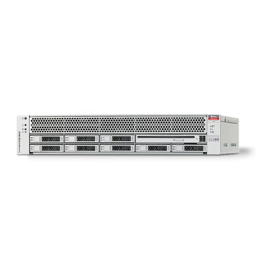
“Cable Management Notes for Both Servers” on page 18 ■ Server Overview The Sun SPARC Enterprise T5140 server from Oracle is a 1 rack unit (1U) server. Oracle’s Sun SPARC Enterprise T5240 server is a 2 rack unit (2U) server. - Page 13 Sun SPARC Enterprise T5140 Server FIGURE: Related Information Sun SPARC Enterprise T5140 and T5240 Servers Getting Started Guide ■ Sun SPARC Enterprise T5140 and T5240 Servers Getting Started Guide (DC) ■ Sun SPARC Enterprise T5140 and T5240 Servers Installation Guide • December 2010...
-
Page 14: Server Handling Precautions
Sun SPARC Enterprise T5140 and T5240 Servers Getting Started Guide (DC) ■ Input Power Information and Precautions The Sun SPARC Enterprise T5140 and T5240 servers are available in the following input power configurations: Two redundant, hot-swappable AC power supplies ■... -
Page 15: Tools And Equipment Needed
Service actions which require removal of one of the power supplies. ■ Refer to the Sun SPARC Enterprise T5140 and T5240 Servers Site Planning Guide for input power specifications. Note – Input AC/DC power cables: To avoid missing initialization messages, do not... -
Page 16: Optional Component Installation
Related Information Sun SPARC Enterprise T5140 and T5240 Servers Getting Started Guide ■ Sun SPARC Enterprise T5140 and T5240 Servers Getting Started Guide (DC) ■ Sun SPARC Enterprise T5140 and T5240 Servers Service Manual ■... -
Page 17: Esd Precautions
Related Information “Installation Overview” on page 6 ■ Installation Overview This installation guide provides procedures that are to be performed in the following order. Sun SPARC Enterprise T5140 and T5240 Servers Installation Guide • December 2010... - Page 18 Installation Overview FIGURE: Figure Legend Preparing for installation Installing the hardware Configuring the service processor Configuring the host software Preparing for Installation...
-
Page 19: Prepare For Installation
2. Connect the server to a serial terminal or a terminal emulator (PC or “Powering On the System for the workstation) to display system messages. See First Time” on page Sun SPARC Enterprise T5140 and T5240 Servers Installation Guide • December 2010... -
Page 20: Configure The Service Processor
Diagnostic test failures will be printed on the serial terminal. For more information, refer to the Integrated Lights Out Manager Supplement for Sun SPARC Enterprise T5140 and T5240 Servers. 3. Connect the data cables to the server, but do not connect the AC power cable yet. -
Page 21: Cabling Notes For Both Servers
Solaris OS configuration procedure. 2. Install any required patches to the server. Refer to the Sun SPARC Enterprise T5140 and T5240 Servers Product Notes for a list of required patches. 3. Load additional software from the Solaris media kit (optional). - Page 22 The service processor network management port uses an RJ-45 cable for a ■ 10/100 BASE-T connection. This port does not support connections to Gigabit networks. See the Sun SPARC Enterprise T5140 and T5240 Servers Overview for more information. Ethernet ports are labeled NET0, NET1, NET2, and NET3. The Ethernet interfaces ■...
-
Page 23: Port, Connector, And Led Locations For Both Servers
Port, Connector, and LED Locations for Both Servers See the figures below for the locations of the ports on the Sun SPARC Enterprise T5140 server. Rear Panel Cable Connectors and LEDs on the Sun SPARC Enterprise T5140 Server FIGURE: Figure Legend Power supply 0... - Page 24 Front Panel USB Ports on the Sun SPARC Enterprise T5140 Server FIGURE: Figure Legend System status indicators: Top to bottom: Locator LED button, Service Hard drive HDD3 Required LED, Power OK LED, and Power button Hard drive HDD0 USB port 2...
-
Page 25: Related Information
Sun SPARC Enterprise T5140 and T5240 Servers Getting Started Guide ■ Sun SPARC Enterprise T5140 and T5240 Servers Getting Started Guide (DC) ■ Sun SPARC Enterprise T5140 and T5240 Servers Service Manual ■ Sun SPARC Enterprise T5140 and T5240 Servers Installation Guide • December 2010... -
Page 26: Slide Rail Assembly Notes For Both Servers
Note – The slide rail assemblies are different for the T5140 and T5240 servers. The removable mounting bracket of the Sun SPARC Enterprise T5140 rail slides 13 in. (33 cm) out of the slide rail, then locks in place. The removable mounting bracket of the Sun SPARC Enterprise T5240 rails slide 14 in. - Page 27 ■ bracket. One lock is on the front section of the slide rail. “Installing the Servers in a Rack” on page 19 describes the uses of these locks. Sun SPARC Enterprise T5140 and T5240 Servers Installation Guide • December 2010...
- Page 28 Locating the Locks on the Slide Rail Assembly for the Sun SPARC Enterprise FIGURE: T5240 Server Preparing for Installation...
-
Page 29: Cable Management Notes For Both Servers
The CMA clips onto the slide rails. Use the velcro straps to secure cabling to the CMA. Cable Management Arm for Both Servers FIGURE: Related Information “Managing Cables With the CMA” on page 39 ■ Sun SPARC Enterprise T5140 and T5240 Servers Installation Guide • December 2010... -
Page 30: Installing The Sun Sparc Enterprise T5140 And T5240 Servers
Installing the Sun SPARC Enterprise T5140 and T5240 Servers This chapter provides instructions for installing the servers into an equipment rack. Note – If your rackmounting kit came with its own instructions, use the instructions in your rackmounting kit instead of the instructions in this chapter. After performing the server installation, proceed to “Powering On the System”... - Page 31 Pull the mounting bracket out until it locks in the extended position. c. Slide the mounting bracket release button, then slide the mounting bracket out of the slide rail. Sun SPARC Enterprise T5140 and T5240 Servers Installation Guide • December 2010...
- Page 32 Location of the Mounting Bracket Release Button (Either Server) FIGURE: d. Press the metal lever (labeled Push) on the middle section of the sliding rail, then push the middle section back into the rack. Installing the Sun SPARC Enterprise T5140 and T5240 Servers...
- Page 33 Position the mounting bracket against the chassis. Ensure that the slide rail lock is at the front and the three keyed openings on the mounting bracket are aligned with the three locating pins on the side of the chassis. Sun SPARC Enterprise T5140 and T5240 Servers Installation Guide • December 2010...
- Page 34 If your rack has threaded mounting holes in the rack posts, determine whether ■ the threads are metric or standard. Select the appropriate screws from the package included in the mounting kit. Installing the Sun SPARC Enterprise T5140 and T5240 Servers...
- Page 35 7. Attach the second slide rail to the left rack posts in a similar manner. Do not tighten the screws. 8. Use the slide rail spacing tool to adjust the distance between the slide rails. Sun SPARC Enterprise T5140 and T5240 Servers Installation Guide • December 2010...
- Page 36 At the rear of the rack, repeat Step a through Step d for the rear ends of the rails. Related Information “Insert and Lock the Server in the Rack” on page 26 ■ Installing the Sun SPARC Enterprise T5140 and T5240 Servers...
- Page 37 2. Insert the ends of the mounting brackets into the sliding rails. Mounting the Chassis on the Slide Rails (Either Server) FIGURE: Sun SPARC Enterprise T5140 and T5240 Servers Installation Guide • December 2010...
-
Page 38: Installing The Cable Management Arm For Both Servers
The tab at the front of the rail extension clicks into place. The right sides of the two CMA arms have hinged extensions. On the manufacturer’s instruction sheet, the smaller extension is called the CMA Connector for Inner Installing the Sun SPARC Enterprise T5140 and T5240 Servers... - Page 39 3. Insert the smaller extension into the clip located at the end of the mounting bracket. Slide the smaller extension into the square hole on the middle-in-width of the clip that is located at the end of the mounting bracket. Sun SPARC Enterprise T5140 and T5240 Servers Installation Guide • December 2010...
- Page 40 Mounting the Inner CMA Connector (Either Server) FIGURE: 4. Insert the larger extension into the end of the right sliding rail. Installing the Sun SPARC Enterprise T5140 and T5240 Servers...
- Page 41 5. Insert the hinged plastic connector at the left side of the CMA fully into the CMA rail extension. The plastic tab on the CMA rail extension locks the hinged plastic connector in place. Sun SPARC Enterprise T5140 and T5240 Servers Installation Guide • December 2010...
-
Page 42: Verify The Operation Of The Slide Rails And The Cma
CMA. 1. For a free-standing rack, deploy the antitilt bar. 2. Unlock the slide lock button s at the right and left sides of the chassis. Installing the Sun SPARC Enterprise T5140 and T5240 Servers... - Page 43 7. Pull both slide rail release buttons toward you simultaneously and slide the server back into the rack. The server should slide smoothly into the rack without binding. Sun SPARC Enterprise T5140 and T5240 Servers Installation Guide • December 2010...
-
Page 44: Connecting The Server Cables For Both Servers
To boot the server, you must connect and configure the network and serial ports. The procedures are given in the following sections. The servers also have serial and USB ports available for connections to optional device. Installing the Sun SPARC Enterprise T5140 and T5240 Servers... -
Page 45: Connect The Service Processor Serial Management Port
Use this port for server management. This port is needed to set up the service processor network management port, as detailed in “Enable the Service Processor Network Management Port” on page Sun SPARC Enterprise T5140 and T5240 Servers Installation Guide • December 2010... -
Page 46: Connect The Service Processor Network Management Port
Network Management Port” on page Note – This port is not operational until you configure the network settings (through the serial management port), as detailed in “Configure the Service Processor Network Management Port” on page Installing the Sun SPARC Enterprise T5140 and T5240 Servers... -
Page 47: Connect The Ethernet Network Cables
NET0 is the farthest left port in the 4-port network cluster. 2. Connect Category 5 cables from your network switch or hub to the remaining Ethernet ports (NET1, NET2, NET3), as needed. Sun SPARC Enterprise T5140 and T5240 Servers Installation Guide • December 2010... -
Page 48: Ac Power Cable Notes
Caution – The server goes into Standby mode and the service processor initializes as soon as the AC power cable is connected to the power source. Related Information “Powering On the System for the First Time” on page 41 ■ Installing the Sun SPARC Enterprise T5140 and T5240 Servers... -
Page 49: Managing Cables With The Cma
Caution – Verify the operation of the slide rails and CMA, and cable service loops. 2. Perform the steps in the following procedure again before continuing: “Verify the Operation of the Slide Rails and the CMA” on page Sun SPARC Enterprise T5140 and T5240 Servers Installation Guide • December 2010... -
Page 50: Dismounting The Servers
To install or replace internal parts in the server, you must first remove the server from the rack. Related Information “Secure the Server Cables in the CMA” on page 39 ■ Sun SPARC Enterprise T5140 and T5240 Servers Service Manual ■ Installing the Sun SPARC Enterprise T5140 and T5240 Servers... - Page 51 Sun SPARC Enterprise T5140 and T5240 Servers Installation Guide • December 2010...
-
Page 52: Powering On The System
Powering On the System This chapter includes instructions for booting the servers and for enabling the service processor network management port. This chapter contains the following topics: “Powering On the System for the First Time” on page 41 ■ “Enable the Service Processor Network Management Port” on page 47 ■... -
Page 53: Ilom System Console
“Power On the System for the First Time” on page For a more detailed discussion on configuring the system console and connecting terminals, refer to the Sun SPARC Enterprise T5140 and T5240 Servers Administration Guide. Related Information “ILOM Service Processor” on page 42 ■... -
Page 54: Power On The System For The First Time
▼ Power On the System for the First Time 1. Confirm that you have completed all of the preparations for installation. See the instructions in “Preparing for Installation” on page 2. Confirm that you have completed the installation of the server in its rack. See the instructions in “Installing the Servers in a Rack”... - Page 55 “Assembling and Installing DC Power Cables for ■ the Sun SPARC Enterprise T5140 Server” on page 7. Plug the power cords into the power supplies and into a power source. Sun SPARC Enterprise T5140 and T5240 Servers Installation Guide • December 2010...
- Page 56 Note – Only one power connection is required for operation. Use two power connections for redundancy. The service processor runs on the 3.3V standby voltage. As soon as AC power is connected to the system, the service processor powers on, runs diagnostics, and initializes the ILOM firmware.
- Page 57 Use the NFSv4 domain derived by the system. Time Zone (Continent) Select your continent. Time Zone (Country or Select your country or region. Region) Sun SPARC Enterprise T5140 and T5240 Servers Installation Guide • December 2010...
-
Page 58: Enable The Service Processor Network Management Port
“Enable the Service Processor Network Management Port” on page 47 ■ ■ Solaris Documentation Sun SPARC Enterprise T5140 and T5240 Servers Administration Guide. ■ Enable the Service Processor Network Management Port The service processor network management port is not operational unless your network employs DHCP, in which case the configuration in automatic. - Page 59 Service Processor Network Management Port” on page You can now use the network management port at any time to access the service processor. Related Information “Logging Into the Service Processor” on page 49 ■ Sun SPARC Enterprise T5140 and T5240 Servers Installation Guide • December 2010...
-
Page 60: Logging Into The Service Processor
Logging Into the Service Processor If you are powering on the system for the first time after installation, use the service processor serial port to power on the system and run POST. See “Log Into the Service Processor Using the Serial Management Port” on page If the network management port has already been configured, you can use it instead of the serial management port. -
Page 61: Configure The Service Processor Network Management Port
Use this procedure only when: You are unable to use DHCP on your network. ■ You need to modify the ILOM service processor network management port ■ settings. Sun SPARC Enterprise T5140 and T5240 Servers Installation Guide • December 2010... - Page 62 Note – For more information on configuring ILOM, refer to the Integrated Lights Out Manager Supplement for Sun SPARC Enterprise T5140 and T5240 Servers. Set these network parameters according to the specific details of your network configuration: /SP/network state –...
- Page 63 = dhcp ipgateway = xxx.xxx.xxx.xxx ipnetmask = 255.255.252.0 macaddress = 00:14:4F:3F:8C:AF pendingipaddress = xxx.xxx.xxx.xxx pendingipdiscovery = static pendingipgateway = xxx.xxx.xxx.xxx pendingipnetmask = 255.255.255.0 state = enabled Commands: show -> Sun SPARC Enterprise T5140 and T5240 Servers Installation Guide • December 2010...
-
Page 64: Log Into The Service Processor Using The Network Management Port
Related Information “Configure the Service Processor Network Management Port” on page 50 ■ Sun SPARC Enterprise T5140 and T5240 Servers Administration Guide ■ ▼ Log Into the Service Processor Using the Network Management Port Note – You must configure the service processor parameters shown in “Configure... -
Page 65: Using The Service Processor For Common Operations
The CPU and memory controllers initialize, and eventually OpenBoot initializes. After a number of system console messages, the ok prompt appears, or the system will boot into the Solaris OS. Sun SPARC Enterprise T5140 and T5240 Servers Installation Guide • December 2010... -
Page 66: Examine The System For Faults
Integrated Lights Out Manager (ILOM) ■ Documentation (http://docs.sun.com/app/docs/prod/int.lights.mgr Sun SPARC Enterprise T5140 and T5240 Servers Administration Guide ■ ▼ Examine the System for Faults 1. Perform the following steps to verify that there are no faults: Powering On the System... - Page 67 SPARC Enterprise T5240, No Keyboard Copyright 2007 Sun Microsystems, Inc. All rights reserved. OpenBoot 4.27.x, 3968 MB memory available, Serial #74409918. Ethernet address 0:14:4f:6f:67:be, Host ID: 846f67be. {8} ok Sun SPARC Enterprise T5140 and T5240 Servers Installation Guide • December 2010...
-
Page 68: Devices In The Openboot Device Tree
Integrated Lights Out Manager (ILOM) 3.0 Supplement for SPARC Enterprise T5140 ■ and T5240 Servers Sun SPARC Enterprise T5140 and T5240 Servers Administration Guide ■ Devices in the OpenBoot Device Tree To understand the various devices and their path names as represented in the OpenBoot device tree, refer to the tables below. -
Page 69: Booting The Solaris Operating System
■ “Avoid Booting the Solaris Operating System at Startup” on page 59 ■ “Reset the System” on page 60 ■ “Power Cycle the System” on page 60 ■ Sun SPARC Enterprise T5140 and T5240 Servers Installation Guide • December 2010... -
Page 70: Avoid Booting The Solaris Operating System At Startup
Related Information Sun SPARC Enterprise T5140 and T5240 Servers Administration Guide ■ ▼ Boot the Solaris Operating System 1. At the ok prompt, boot from the disk that contains the Solaris OS. If you need to determine which disk to boot from, type the show-disks... -
Page 71: Reset The System
91 system services are now being stopped. Jun 12 19:46:57 wgs40-58 syslogd: going down on signal 15 svc.startd: The system is down. syncing file systems... done Program terminated r)eboot, o)k prompt, h)alt? Sun SPARC Enterprise T5140 and T5240 Servers Installation Guide • December 2010... - Page 72 Are you sure you want to start /SP/console (y/n)? y Serial console started. To stop, type #. The systems displays various messages, followed by the ok prompt. Related Information Sun SPARC Enterprise T5140 and T5240 Servers Administration Guide ■ Solaris Documentation ■ Powering On the System...
-
Page 73: Verifying System Functionality
After powering on the system for the first time, you can use the Sun Validation Test Suite (SunVTS) software to verify the functionality and performance of any installed components, as well as its network connections. Related Information ■ SunVTS Documentation Sun SPARC Enterprise T5140 and T5240 Servers Installation Guide • December 2010... -
Page 74: Updating The Firmware
Updating the Firmware This section provides instructions for updating SP firmware. “flashupdate command” on page 63 ■ “Update the Firmware” on page 64 ■ flashupdate command The flashupdate command updates both the service processor firmware and the server firmware. The flash image consists of the following components: Service processor firmware ■... -
Page 75: Update The Firmware
The load command updates the service processor flash image and the host firmware. The load command requires the following information: IP address of a TFTP server on the network that can access the flash image ■ Sun SPARC Enterprise T5140 and T5240 Servers Installation Guide • December 2010... - Page 76 Full path name to the flash image that the IP address can access ■ The command usage is as follows: load [-script] -source tftp://xxx.xxx.xx.xx/pathname where: -script – Does not prompt for confirmation and acts as if yes was specified ■ -source –...
- Page 77 Starting OpenBSD Secure Shell server: sshd. Starting Servicetags listener: stlistener. Starting FRU update program: frutool. hostname login: Related Information “Configure the Service Processor Network Management Port” on page 50 ■ Sun SPARC Enterprise T5140 and T5240 Servers Installation Guide • December 2010...
-
Page 78: Selecting A Boot Device
Sun SPARC Enterprise T5140 and T5240 Servers Administration Guide. Note – The serial management port on the ILOM card is preconfigured as the default system console port. For more information, see the Sun SPARC Enterprise T5140 and T5240 Servers Overview. -
Page 79: Select A Boot Device
The show-devs command lists the system devices and displays the full path name of each PCI device. Related Information OpenBoot Documentation ■ OpenBoot Command Reference Manual ■ Sun SPARC Enterprise T5140 and T5240 Servers Installation Guide • December 2010... -
Page 80: Installing The Servers With The Express Rail Rackmounting Kit
Installing the Servers With the Express Rail Rackmounting Kit This chapter provides instructions for installing the servers in an equipment rack with express (snap-in) rails. “Slide Rail Assembly Notes for the Express Rail Rackmounting Kit” on page 69 ■ “Install the Slide Rail Assemblies” on page 72 ■... - Page 81 There are six locks in a slide rail assembly. Four are on the mounting bracket. Two ■ locks are on the slide rail. Sun SPARC Enterprise T5140 and T5240 Servers Installation Guide • December 2010...
- Page 82 Locating the Locks on the Slide Rail Assembly for the Sun SPARC Enterprise FIGURE: T5240 Server Related Information “Install the Slide Rail Assemblies” on page 72 ■ “Insert and Lock the Server in the Rack” on page 77 ■ Installing the Servers With the Express Rail Rackmounting Kit...
-
Page 83: Install The Slide Rail Assemblies
Simultaneously press and hold the upper and lower lock buttons of the slide rail lock. Unlocking the Express Rail Slide Rail Assembly FIGURE: b. Pull the mounting bracket out until it stops. Sun SPARC Enterprise T5140 and T5240 Servers Installation Guide • December 2010... - Page 84 c. Slide the mounting bracket release button to the left; then slide the mounting bracket completely out of the slide rail. Express Rail Mounting Bracket Release Button FIGURE: 2. Attach a mounting bracket to the right side of the server chassis. a.
- Page 85 3. Attach the second mounting bracket to the left side of the server chassis. 4. Orient slide rails, ensuring that the ball bearing tracks (labeled FRONT) are forward. Sun SPARC Enterprise T5140 and T5240 Servers Installation Guide • December 2010...
- Page 86 Express Rail Slide Rails Orientation for Installation FIGURE: 5. Extend the slide rails (outer section) to fit the rack and attach the slide rails to the rack. You hear an audible click when the rails securely attach to the rack. Installing the Servers With the Express Rail Rackmounting Kit...
- Page 87 FIGURE: Caution – Deploy the antitilt feature on the rack before continuing the installation. Related Information “Insert and Lock the Server in the Rack” on page 77 ■ Sun SPARC Enterprise T5140 and T5240 Servers Installation Guide • December 2010...
-
Page 88: Insert And Lock The Server In The Rack
▼ Insert and Lock the Server in the Rack 1. Deploy the antitilt feature, if the rack is so equipped. Caution – The weight of the servers on extended slide rails can be enough to overturn an equipment rack. Caution – The 2U server weighs approximately 55 lb (25 kg). Two people are required to lift and mount the server into a rack enclosure when using the procedures in this chapter. -
Page 89: Dismounting The Server
Dismounting the Server Caution – To prevent damage to your server, do not move the rack while the server is mounted. Sun SPARC Enterprise T5140 and T5240 Servers Installation Guide • December 2010... - Page 90 To install or replace internal parts in the server, you must first remove the server from the rack. Related Information Sun SPARC Enterprise T5140 and T5240 Servers Service Manual ■ Installing the Servers With the Express Rail Rackmounting Kit...
- Page 91 Sun SPARC Enterprise T5140 and T5240 Servers Installation Guide • December 2010...
-
Page 92: Assembling And Installing Dc Power Cables For The Sun Sparc Enterprise T5140 Server
Server” on page 93 Requirements for Servers With DC Input Power The following restrictions apply to the Sun SPARC Enterprise T5140 server with DC input power: The DC version of the server must be installed in a restricted-access location. ■... -
Page 93: Dc Supply And Ground Conductor Requirements
The DC battery power source must be in the same premises as the server. The server cannot be in one building with the power source in another building. Sun SPARC Enterprise T5140 and T5240 Servers Installation Guide • December 2010... -
Page 94: Overcurrent Protection Requirements
■ ▼ Assemble the DC Input Power Cable The following procedure describes how to assemble the DC input power cables for Oracle’s Sun SPARC Enterprise T5140 server. Assembling and Installing DC Power Cables for the Sun SPARC Enterprise T5140 Server... - Page 95 2. Identify the parts that you will use to assemble the DC input power cables For each cable, you need the items shown in. These items are provided in the shipping kit that came with your server. Sun SPARC Enterprise T5140 and T5240 Servers Installation Guide • December 2010...
- Page 96 Note – Depending on the DC power source, the -48V or -60V (negative terminal) might be marked with a minus (-) symbol. The -48V or -60V Return (positive terminal) might be marked with a positive (+) symbol. Assembling and Installing DC Power Cables for the Sun SPARC Enterprise T5140 Server...
- Page 97 Insert a small slotted screwdriver into the rectangular hole directly above the ■ hole in the DC input plug where you want to insert the first wire, and push in to open the cage clamp. Sun SPARC Enterprise T5140 and T5240 Servers Installation Guide • December 2010...
- Page 98 Opening the DC Input Plug Cage Clamp Using the Cage Clamp Operating FIGURE: Lever Assembling and Installing DC Power Cables for the Sun SPARC Enterprise T5140 Server...
- Page 99 DC input plug. 7. Release the lever or remove the tool to secure the wire into the connector. Sun SPARC Enterprise T5140 and T5240 Servers Installation Guide • December 2010...
-
Page 100: Install The Strain Relief Housings
Inserting the Bottom Portion of the Strain Relief Housing FIGURE: 2. Route the three wires coming from the DC power source through the opening at the bottom end of the strain relief housing. Assembling and Installing DC Power Cables for the Sun SPARC Enterprise T5140 Server... - Page 101 DC input plug. Push the top and bottom portions of the strain relief housing together until they snap into place. Sun SPARC Enterprise T5140 and T5240 Servers Installation Guide • December 2010...
-
Page 102: Connect The Dc Input Power Cords To The Server
2. Route the power cables in the rack and secure the cables with nylon tie wraps. 3. Connect the chassis ground wire to the facility earth ground and ensure that this connection has proper bonding. Assembling and Installing DC Power Cables for the Sun SPARC Enterprise T5140 Server... - Page 103 6. When you are ready to power up the server, close the circuit breaker and follow the booting procedure described in “Powering On the System” on page Related Information “Assembling and Installing the DC Input Power Cables” on page 83 ■ Sun SPARC Enterprise T5140 and T5240 Servers Installation Guide • December 2010...
-
Page 104: Assembling And Installing Dc Power Cables For The Sun Sparc Enterprise T5240 Server
“Overcurrent Protection Requirements” on page 95 ■ “Assembling and Installing the DC Input Power Cables” on page 95 ■ Related Information “Assembling and Installing DC Power Cables for the Sun SPARC Enterprise T5140 ■ Server” on page 81 Requirements for Servers With DC Input Power... -
Page 105: Dc Supply And Ground Conductor Requirements
The DC battery power source must be in the same premises as the server. The server cannot be in one building with the power source in another building. Sun SPARC Enterprise T5140 and T5240 Servers Installation Guide • December 2010... -
Page 106: Overcurrent Protection Requirements
▼ Assemble the DC Input Power Cables The following procedure describes how to assemble the DC input power cables for Oracle’s Sun SPARC Enterprise T5240 server. Assemble one cable for each DC power supply in your server. Assembling and Installing DC Power Cables for the Sun SPARC Enterprise T5240 Server... - Page 107 These items are provided in the shipping kit that came with your server (DC models only). DC Connection Parts FIGURE: Figure Legend DC input plug Cage clamp operating tool or small screwdriver Sun SPARC Enterprise T5140 and T5240 Servers Installation Guide • December 2010...
- Page 108 3. Locate the three wires coming from your DC power source that will be used in the connection to your unit: -48V or -60V (negative terminal) ■ Chassis ground ■ -48V or -60V Return (positive terminal) ■ Note – Depending on the DC power source, the -48V or -60V (negative terminal) might be marked with a minus (-) symbol.
- Page 109 Note – If you need to remove a wire from the DC input plug, insert the cage clamp operating tool or a small screwdriver into the slot directly above the wire and push in. Pull the wire from the DC input plug. Sun SPARC Enterprise T5140 and T5240 Servers Installation Guide • December 2010...
- Page 110 7. Remove the cage clamp tool to secure the wire. 8. Repeat the procedures for the other two wires to complete the assembly of the DC input power cable. 9. Repeat this procedure to create as many DC input power cables as you need for your unit.
- Page 111 Sun SPARC Enterprise T5140 and T5240 Servers Installation Guide • December 2010...
-
Page 112: Index
Index Symbols show-disks, 59 uadmin, 60, 61 #. escape sequence for system console, 61 command-line access, ILOM, 49 configuration information needed, 8 configuring the network management port, 47 accessing ILOM command line, 49 connecting to the system console, 58 adapters for serial cables, 36 console command, 62 address, IP, 8 addresses, web, See web sites... - Page 113 72 powering on for the first time, 43 unlocking, 72 powering on the system, 54 mounting screws for rack, 23 set command, 51 service processor,See also ILOM Sun SPARC Enterprise T5140 and T5240 Servers Installation Guide • December 2010...
- Page 114 set command, 51 set keyswitch command, 56, 57 show /SP/network command, 52 show-disks command, 59 slide rail assembly locks illustrated front slide rail locks, 20 middle section lever, 22 mounting bracket locating pin lock, 23 mounting bracket release button, 21 slide rail spacing tool, 25 slots, ports, and LEDs illustrated, 13 slots, ports, and LEDs, illustrated, 12...
- Page 115 Sun SPARC Enterprise T5140 and T5240 Servers Installation Guide • December 2010...
Need help?
Do you have a question about the Sun SPARC Enterprise T5140 and is the answer not in the manual?
Questions and answers