
Related Manuals for BMW R 1100 RT


Summary of Contents for BMW R 1100 RT
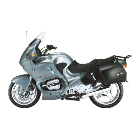
- Page 1 Repair Manual R 1100 RT R 1100 RS R 850/1100 GS R 850/1100 R BMW Motorcycle After Sales...
- Page 2 Published by: © BMW Motorcycle After Sales UX-VS-2 All rights reserved. Not to be reprinted, translated or duplicated either wholly or in part without prior written permission. Errors and omissions excepted; subject to technical amendment. Produced in Germany 02/00...
- Page 3 All information in both text and illustrations refers to motorcycles in standard condition or with genuine BMW accessories installed, and not to motorcycles which have been modified in any way to depart from the manufacturer’s specification. The repair manual is structured in the logical sequence of the work to be performed: Removal, Dis- assembly, Repair, Assembly, Installation.
- Page 4 Contents << Back Group / Chapter 00 Maintenance and general instructions 11 Motor 12 Engine electrics 13 Fuel preparation and control 16 Fuel tank and lines 18 Exhaust system 21 Clutch 23 Gearbox 31 Front fork 32 Steering 33 Rear wheel drive >>...
- Page 5 >> Continuation Group / Chapter 34 Brakes 36 Wheels and tyres 46 Frame 51 Equipment 52 Seat 61 General electrical equipment 62 Instruments 63 Lights << Back...
- Page 6 BMW AG Motorcycle Division Maintenance Schedule R 1100 RT/R 1100 RS/R 850 GS/R 1100 GS/R 850R/R 1100 R Customer Registration No. Order No. Signature of mechanic Change engine oil when engine is warm, renew oil filter cartridge Change oil in manual transmission and rear wheel drive when at operating temperature...
- Page 7 BMW AG Motorcycle Division Pre-delivery check R 1100 RT/R 1100 RS/R 850 GS/R 1100 GS/R 850R/R 1100 R Customer Registration No. Pre-delivery check Order No. Signature of mechanic Inspect crates on receipt for signs of damage Motorcycle: – unpack –...
-
Page 8: Service Data
BMW AG Motorcycle Division Service Data R 1100 RT/R 1100 RS/R 1100 GS/R 1100 R/R 850 R Designation Data Measuring unit or specification Oilcapacities Engine (incl. filter) 3.75 litre Engine (without filter renewal) 5.50 litre [SI 11 048 90] Brand-name HD oil for petrol engines of API classi- fication SE, SF, SG;... -
Page 9: Maintenance And General Instructions
00 Maintenance and general instructions Contents Page Tightening torques R 1100 RS / R 1100 RT ..............3 Tightening torques R 850/1100 GS und R 850/1100 R ...........12 Operating materials ........................21 Key to maintenance intervals ....................22 Change engine oil, renew oil filter element ..............22... -
Page 10: Table Of Contents
Contents Page Checking brake pads for wear ....................32 Renewing brake pads – front brake ..................32 [RS] Renewing brake pads - rear brake ................33 [GS/R/RT] Renewing brake pads - rear brake ..............33 Checking brake discs for wear ....................33 Checking brake fluid level/topping up ................33 (Inspection III) ............................33 Bleeding/renewing the brake fluid using the handbrake lever/... -
Page 11: Tightening Torques R 1100 Rs / R 1100 Rt
Tightening torques R 1100 RS / R 1100 RT Model R 1100 RS R 1100 RT 11 Engine Connection Cylinder head Tightening sequence: 1. Tighten cylinder head nuts (oiled) crosswise 1.1 Tighten all nuts to correct torque for joint 1.2 Tighten all nuts to correct angle 90°... - Page 12 Model R 1100 RS R 1100 RT 11 Engine Connection Oil filter Oil filter Oil drain plug Oil pump Mesh filter basket to engine block Oil pump cover Pressure relief valve Oil pressure switch Oil cooler Oil cooler pipe to engine block...
- Page 13 Model R 1100 RS R 1100 RT 12 Engine electrical system Connection Starter motor to engine Starter cover to gearbox housing – Positive lead to starter motor Alternator to alternator support cover Tensioning and retaining strap at alternator Spacer at alternator...
- Page 14 Model R 1100 RS R 1100 RT 21 Clutch Connection Clutch housing Joint torque oil screw threads lightly Additional wrench angle 32° Housing cover Locknut on release lever 23 Gearbox Oil filler plug Oil drain plug Gearbox cover to gearbox housing...
- Page 15 Model R 1100 RS R 1100 RT 31 Front fork Connection Clamp between fixed tubes and fork bridge – Screw connection between fixed tube and – 45 (free from oil and fork bridge grease) Control arm to ball joint clean thread + Loctite 2701 Fork bridge to ball joint –...
- Page 16 Model R 1100 RS R 1100 RT 33 Rear wheel drive Connection Oil drain plug Oil filler plug Threaded ring 118 (Hylomar SQ 32 M) 118 (Hylomar SQ 32 M) Hexagon nut, input bevel gear clean thread + Loctite 273...
- Page 17 Model R 1100 RS R 1100 RT 34 Brakes Connection Brake caliper to slider tube Brake caliper to rear wheel drive Brake disc to front wheel Brake disc to rear wheel drive clean thread + Loctite 273 Brake hose to brake caliper, front/rear...
- Page 18 Model R 1100 RS R 1100 RT 46 Frame Connection Rear frame to gearbox/engine Screw connection on right of gearbo at right of engine at left of engine at left of gearbox Footrest plate to gearbox Frame to engine Struts to frame 8.8 screw...
- Page 19 Model R 1100 RS R 1100 RT 51 Equipment Connection Ignition/steering lock to fork bridg 61 General electrical system Horn to horn bracket Ground (earth) strap to engine block Rubber bushing for battery holder at gearbox 00.11...
-
Page 20: Tightening Torques R 850/1100 Gs Und R 850/1100 R
Tightening torques R 850/1100 GS und R 850/1100 R Model R 850/1100 GS R 850/1100 R 11 Engine Connection Cylinder head Tightening sequence: 1. Tighten cylinder head nuts (oiled) crosswise 1.1 Tighten all nuts to correct torque for joint 1.2 Tighten all nuts to correct angle 90°... - Page 21 Model R 850/1100 GS R 850/1100 R 11 Engine Connection Oil filter Oil filter Oil drain plug Oil pump Mesh filter basket to engine block Oil pump cover Pressure relief valve Oil pressure switch Oil cooler Oil cooler pipe to engine block Cooling oil line - banjo screw Cooling oil line - banjo screw with oil vent valve Oil lines to oil cooler...
- Page 22 Model R 850/1100 GS R 850/1100 R 12 Engine electrical system Connection Starter motor to engine Starter cover to gearbox housing Positive lead to starter motor Alternator to alternator support cover Tensioning and retaining strap at alternator Spacer at alternator Positive lead to alternator Belt pulley at alternator Belt pulley to crankshaft...
- Page 23 Model R 850/1100 GS R 850/1100 R 21 Clutch Connection Clutch housing Joint torque oil screw threads lightly Additional wrench angle 32° Housing cover Locknut on release lever 23 Gearbox Oil filler plug Oil drain plug Gearbox cover to gearbox housing Screw for neutral detent clean thread + Loctite 243 Oil guide plate at gearbox housing...
- Page 24 Model R 850/1100 GS R 850/1100 R 31 Front fork Connection Screw connection between fixed tube and 45 (free from oil and 45 (free from oil and fork bridge grease) grease) Control arm to ball joint clean thread + Loctite 2701 Threaded journal to frame clean threads + Loctite 243 Ball joint to...
- Page 25 Model R 850/1100 GS R 850/1100 R 32 Steering Connection Handlebar to fork bridge Twistgrip to handlebar Handlebar weight to fixed handlebar 33 Rear wheel drive Oil drain plug Oil filler plug Threaded ring 118 (Hylomar SQ 32 M) 118 (Hylomar SQ 32 M) Hexagon nut, input bevel gear clean thread + Loctite 273 Housing cover...
- Page 26 Model R 850/1100 GS R 850/1100 R 34 Brakes Connection Brake caliper to slider tube Brake caliper to rear wheel drive Brake disc to front wheel Cast wheel – Spoked whee clean thread + Loctite 243 Brake disc to rear wheel drive clean thread + Loctite 273 Brake disc to rear wheel clean thread + Loctite 243...
- Page 27 Model R 850/1100 GS R 850/1100 R 36 Wheels and tyres Connection Clamping screws, quick-release axle Screw connection, quick-release axle Screw on wheel nuts handtight, then tighten crosswise: Initial tightening Final tightening 46 Frame Rear frame to gearbox/engine 1. Screw connection on right of gearbox 2.
- Page 28 Model R 850/1100 GS R 850/1100 R 51 Equipment Connection Ignition/steering lock to fork bridge 61 General electrical system Horn to horn bracket Ground (earth) strap to engine block Rubber bushing for battery holder at gearbox 00.20...
-
Page 29: Operating Materials
Operating materials Item Order number Quantity Lubricant Optimoly MP 3 High-performance lubricating paste 07 55 9 062 476 100 g tube Optimoly TA High-temperature assembly paste 18 21 9 062 599 100 g tube Silicone grease 300, heavy Damping grease 07 58 9 058 193 10 g tube Retinax A (Taper) roller bearing grease... -
Page 30: Key To Maintenance Intervals
11 4 650 RS000180 RS110950 • • Remove screw plug. Using oil filter wrench, BMW No. 11 4 650, • Unscrew oil drain plug and drain off oil. unscrew and remove the oil filter element. • • Fit new seal and screw in drain plug. -
Page 31: Change The Oil In The Gearbox And Rear Wheel Drive
Top up gearbox oil. • Insert oil filler plug with new seal. • [RT] Push in oil drain pipe (1), BMW No. 23 4 680 and turn to right. • Unscrew and remove oil filler plug and oil drain Tightening torque: plug/drain off oil. -
Page 32: Checking Battery Acid Level/Topping Up If Necessary, Cleaning/Greasing
R/GS/RT RS000340 Checking battery acid level/topping Renewing air cleaner up if necessary, cleaning/greasing (Inspection III) battery posts • Remove dualseat. • (Inspection III, IV) [GS] Detach fuel tank at rear, raise it and support it with a suitable object. • •... -
Page 33: Renewing Fuel Filter
[RS/RT] Take off side sections of fairing. Seal off fuel feed and return line (3) with hose clip, • [RS] Detach cockpit inner panel (1) at fuel tank. BMW No. 13 3 010, loosen and pull off. • • [GS] Remove right side fairing. - Page 34 13 3 010 RT160060 00.26...
- Page 35 RS000130 Caution: Fuel is flammable and a hazard to health. Observe relevant safety regulations. • Drain fuel tank. • Remove fuel pump unit/detach vent hoses. 00.27...
- Page 36 • Installation in reverse order. • Secure non-reusable hose clips with pliers, BMW No. 13 1 500. Caution: Note correct direction of flow through fuel filter. Use only an O-ring seal (2) in good condition. After assembly, check fuel pump unit for leaks.
-
Page 37: Checking/Renewing Spark Plugs
Pull off spark plug cap with cap assembly tool, BMW No. 12 3 520. • Unscrew and remove spark plugs with spark- plug wrench, BMW No. 12 3 510. Electrode gap: ......0.8 mm (0.0315 in) RS 00. 002 RS00002 Gap wear limit:...... -
Page 38: Checking/Adjusting Valve Operating Clearances
Checking/adjusting valve operating clearances (Inspection I, II, III) RS110980 • Check valve clearance with feeler gauge and, if necessary, correct with adjusting nut/lock. Adjust valve clearances with the engine cold (max. 35°C): Inlet .......... 0.15 mm ( 0.006 in) Exhaust ........0.30 mm (0.012 in ) Tightening torque: Locknut ............ -
Page 39: Adjusting Poly-V Belt
RS110480 Adjusting Poly-V belt Poly-V belt adjusting procedure: Poly-V belt installation procedure: (Inspection I, II, III) • Place the Poly-V belt in position, tension it and turn the engine over once, then release belt ten- Renewing Poly-V belt sion. (40 000 km/24 000miles) Poly-V belt tensioning procedure: •... -
Page 40: Checking Brake Pads And Discs For Wear/Renewing
Before installing the brake caliper, push the Brake pad thickness must not fall below the minimum pistons back fully with resetting tool, value. BMW No. 34 1 500. • Change pads only as a complete set. Install in the reverse order of work. -
Page 41: Rs] Renewing Brake Pads - Rear Brake
Install in the reverse order of work. [RS] rear:........4.6 mm (0.181 in) • If necessary, push pistons fully back with reset- ting tool, BMW No. 34 1 500. Checking brake fluid level/topping [GS/R/RT] Renewing brake pads - rear brake (Inspection III) Max. -
Page 42: Bleeding Front Brake Circuit/Renewing Fluid
LT000100 • Press the brake pistons fully back with the piston resetting tool, BMW No. 34 1 500. • Remove the piston resetting tool and insert spacer, BMW No. 34 1 520, in its place. 00.34... -
Page 43: Grease The Centre Stand [Rs], Side Stand And Clutch Cable Nipple
Grease the centre stand [RS], side [RS] Cleaning and greasing the stand and clutch cable nipple windshield adjusting shaft (Inspection II, III, IV) (Inspection III) RS000360 RS000330 • • Clean and grease the nipple with a grease gun Unscrew, clean and grease the shaft, then screw until grease starts to emerge at the bearing point. - Page 44 6 mm Allen key, BMW No. 31 5 600. • [RT] Slacken off the power socket holder. • Using socket wrench, BMW No. 21 3 610, slacken off locknut (1) at adjusting screw (2) on the clutch release lever/gearbox. 00.36...
-
Page 45: Checking Tightness Of Rear Wheel Studs
Checking tightness of rear wheel Checking front wheel bearings/ studs checking tilt play at rear wheel (Inspection I) (Inspection III) • Relieve load on front wheel. • Tightening torque: Tilt the front wheel to and fro across the axle. • Rear wheel nuts ......... -
Page 46: Checking Throttle Synchronisation/Co Emission Value
Checking/adjusting throttle syn- chronisation and CO emission value (Inspection I, II, III, IV) RS130040 • Pre-adjust the wire connecting cable between the throttle stub pipes with the left or right ad- justing screw . RS130020 • Adjust the connecting cable to zero play. •... - Page 47 • • Connect the BMW Synchrotester, Set idle speed using recirculating air screws BMW No. 13 0 800, to the vacuum while maintaining synchronous running. bores in the throttle stub pipes. • Ride the motorcycle until the engine is warm, or...
- Page 48 • With cable junction block Connect the BMW Synchrotester, BMW No. 13 0 800, to the vacuum bores of the throttles.. • Ride the motorcycle until the engine is warm, or alternatively allow it to warm up at a standstill for approx. 10 minutes.
- Page 49 • Push the protective rubber cap (2) back over the adjusting screw. Throttle cable play:..app. 0.5 mm (0.0197 in) RT000140 • Rectify any faults found. • Set idle speed using recirculating air screws while maintaining synchronous running. RS 11.055 RT000080 + 150 Idle speed: ........
-
Page 50: Final Inspection With Road Safety And Functional Check
Final inspection with road safety and functional check (Inspection I, II, III, IV) Road safety check • Check wheels and tyres. • Check/correct tyre pressures. Tyre pressures: Rider only......front 2.2 bar(31.9 psi) ........... rear 2.5 bar (36.26 psi) With pillion passenger ..front 2.5 bar(36.26 psi) .......... -
Page 51: Motor
11 Motor Contents Page Technical Data ..........................5 Sectioned drawing of engine ....................37 Lubricating oil circuit .......................38 Coolant circuit ..........................39 Cooling oil circuit (with oil thermostat) ................40 Removing engine ........................41 Fitting auxiliary frame .........................52 Take off auxiliary frame........................53 Dismantling engine ........................54 Removing cylinder head cover ....................55... - Page 52 Contents Page Removing/installing conrod ......................68 Removing and installing alternator cover with engine installed .......69 Removing alternator mount cover ..................69 Renewing radial shaft seal in alternator mount cover ...........70 Renewing radial shaft seal for rotary breather ..............70 Removing auxiliary-shaft drive ....................71 Removing oil pump ........................72 Oil temperature regulator...
- Page 53 Contents Page Installing auxiliary shaft drive ....................88 Installing pistons ..........................89 Installing cylinders ........................90 Installing cylinder head .......................91 Adjusting valve clearances .......................92 Installing right cylinder head ....................93 Adjustment specification ........................93 Installing left cylinder head .......................94 Adjustment specification ........................94 Installing alternator mount cover ....................96 Installing magnetic gate/belt pulley ..................96...
- Page 54 11.4...
- Page 55 Technical Data R 1100 RS Engine, general Engine design Four-stroke flat twin, air-cooled with oil-cooled exhaust ports, installed longitudinally, 4 valves per cylinder, two high-mounted camshafts, elec- tronic fuel injection. Location of engine number Crankcase Cylinder bore mm (in) 99.0 (3.898) Stroke mm (in) 70.5 (2.776)
- Page 56 Technical Data R 1100 RS Valves Included angle between valves ° Valve clearances, engine cold (max. 35 °C) Inlet valve mm (in) 0.15 (0.0059) Exhaust valve mm (in) 0.30 (0.0118) Valve timing Zero valve clearance. 3 mm (0.1181 in) valve lift Inlet opens 5°...
- Page 57 Technical Data R 1100 RS Valve seat ring Valve seat angle Inlet 45° Exhaust 30° from 1996 mod. year on Inlet 45° Exhaust 45° Valve seat width ± 0.15 Inlet mm (in) ± 0.00591 (0.04331 Wear limit mm (in) 2.5 (0.09843) ±...
- Page 58 Technical Data R 1100 RS Valve guide Valve guide Extl. dia. mm (in) 12.533...12.544 (0.49343...0.49386) Bore in cylinder head mm (in) 12.500...12.518 (0.49213...0.49283) Overlap mm (in) 0.015...0.044 (0.00059...0.001732) Repair stages Replacement valve guide Extl. dia. mm (in) 12.550...12.561 (0.49409...0.49453) Oversize valve guide Extl.
- Page 59 Technical Data R 1100 RS Camshaft Opening angle, inlet/exhaust cams 300° Cam spread, inlet/exhaust 106°/109° Marking Marking in position 4 Inlet valve lift mm (in) 9.68 (0.3811) (valve clearance = 0) Exhaust valve lift mm (in) 9.26 (0.36457) (valve clearance = 0) Camshaft bearing bore dia.
- Page 60 Technical Data R 1100 RS Crankshaft Marking of main bearing and crankpin on front crank web no paint mark Grinding stage 0 paint mark Grinding stage 1 -0.25mm (-0.009843 in) Grinding stage 0 (grinding stage 1= —0.25mm) Guide bearing bore dia. mm (in) 64.949...64.969 (2.557047...2.557834)
- Page 61 Technical Data R 1100 RS Width of big end bearing eye mm (in) 21.883...21.935 (0.86154...0.86358) Conrod end float mm (in) 0.130...0.312 (0.005118...0.0122834) Wear limit mm (in) 0.5 (0.019685) Small end bearing bore dia. mm (in) 22.015...22.025 (0.86673...0.867126) Radial clearance mm (in) 0.015...0.030 (0.0005905...0.0018) Wear limit...
- Page 62 Technical Data R 1100 RS Piston rings 1st groove Micro-taper compression ring Height 1.175...1.190 mm (in) (0.04626...0.04685) Wear limit mm (in) 1.1 (0.043307) Gap clearance 0.1...0.3 mm (in) (0.003937...0.0118) Wear limit mm (in) 0.8 (0.031496) Side clearance 0.040...0.075 mm (in) (0.001575...0.002953) Wear limit mm (in)
- Page 63 Technical Data R 1100 RT Engine, general Engine design Four-stroke flat twin, air-cooled with oil-cooled exhaust ports, installed longitudinally, 4 valves per cylinder, two high-mounted camshafts, elec- tronic fuel injection. Location of engine number Crankcase Cylinder bore mm (in) 99.0 (3.898)
- Page 64 Technical Data R 1100 RT Valves Included angle between valves ° Valve clearance with engine cold (max. 35 °C) Inlet valve mm (in) 0.15 (0.0059) Exhaust valve mm (in) 0.30 (0.0118) Valve timing At zero valve clearance and 3 mm (0.1181 in) valve lif Inlet opens 5°...
- Page 65 Technical Data R 1100 RT Seat dia. in cylinder head (oversize +0.2 mm) Inlet mm (in) 37.500...37.525 (1.47638...1.47736) Exhaust mm (in) 34.000...34.025 (1.33859...1.33957) from 1996 mod. year on Inlet mm (in) 36.500...36.525 (1.43701...1.43799) Exhaust mm (in) 32.000...32.025 (1.25984...1.26083) Valve seat ring...
- Page 66 Technical Data R 1100 RT Valve guide Valve guide Extl. dia. mm (in) 12.533...12.544 (0.49343...0.49386) Bore in cylinder head mm (in) 12.500...12.518 (0.49213...0.49283) Overlap mm (in) 0.015...0.044 (0.00059...0.001732) Repair stages Replacement valve guide Extl. dia. mm (in) 12.550...12.561 (0.49409...0.49453) Oversize valve guide Extl.
- Page 67 Technical Data R 1100 RT Camshaft Opening angle, inlet/exhaust cams 300° Cam spread, inlet/exhaust 106°/109° Marking Marking in position 4 Inlet valve lift mm (in) 9.68 (0.3811) (valve clearance = 0) Exhaust valve lift mm (in) 9.26 (0.36457) (valve clearance = 0) Camshaft bearing bore dia.
- Page 68 Technical Data R 1100 RT Crankshaft Marking of main bearing and crankpin on front crank web no paint mark Grinding stage 0 paint mark Grinding stage 1 (-0.25mm (-0.009843)) Grinding stage 0 (grinding stg. 1=—0.25mm) Guide bearing bore dia. mm (in) 64.949...64.969...
- Page 69 Technical Data R 1100 RT Connecting rod Big end bore dia. mm (in) 51.000...51.013 (2.00787...2.008386) Big end bearing dia. mm (in) 48.016...48.050 (1.89039...1.89173) Radial clearance mm (in) 0.025...0.075 (0.000984...0.0029527) Wear limit mm (in) 0.13 (0.001118) Width of big end bearing eye mm (in) 21.883...21.935...
- Page 70 Technical Data R 1100 RT Piston pin bore dia. mm (in) 22.005...22.011 (0.86634...0.866575) Weight classes + and — Weight difference in one class g (oz.) 10 (0.35) (complete with pins and rings) Direction of installation Arrow on piston crown pointing to exhaust side...
- Page 71 Technical Data R 850 GS R 1100 GS Engine, general Engine design Four-stroke flat twin, air-cooled with oil-cooled exhaust ports, installed longitudinally, 4 valves per cylinder, two high-mounted camshafts, elec- tronic fuel injection. Location of engine number Crankcase Cylinder bore mm (in) 87.5 (3.445) 99.0 (3.898) Stroke...
- Page 72 Technical Data R 850 GS R 1100 GS Valves Included angle between valves ° 41 Valve clearance with engine cold (max. 35 °C) Inlet valve mm (in) 0.15 (0.0059) 0.15 (0.0059) Exhaust valve mm (in) 0.30 (0.0118) 0.30 (0.0118) Valve timing At zero valve clearance and 3 mm (0.1181 in) valve li Inlet opens...
- Page 73 Technical Data R 850 GS R 1100 GS Valve seat ring Valve seat angle Inlet 45° 45° Exhaust 45° 30° from 1996 mod. year on Inlet 45° Exhaust 45° Valve seat width ± 0.15 ± 0.15 Inlet mm (in) 1.1 ±...
- Page 74 Technical Data R 850 GS R 1100 GS Valve guide Valve guide Extl. dia. mm (in) 12.533...12.544 12.533...12.544 (0.49343...0.49386) (0.49343...0.49386) Bore in cylinder head mm (in) 12.500...12.518 12.500...12.518 (0.49213...0.49283) (0.49213...0.49283) Overlap mm (in) 0.015...0.044 0.015...0.044 (0.00059...0.001732) (0.00059...0.001732) Repair stages Replacement valve guide Extl. dia. mm (in) 12.550...12.561 12.550...12.561 (0.49409...0.49453)
- Page 75 Technical Data R 850 GS R 1100 GS Camshaft Opening angle, inlet/exhaust cams 300°/284° 300°/284° Cam spread, inlet/exhaust 103°/112° 103°/112° Marking Marking in position 1 Marking in position 1 Inlet valve lift mm (in) 9.68 (0.3811) 9.68 (0.3811) (valve clearance = 0) (valve clearance = 0) Exhaust valve lift mm (in) 8.55 (0.33661)
- Page 76 Technical Data R 850 GS R 1100 GS Crankshaft Marking of main bearing and crankpin on front crank web no paint mark Grinding stage 0 Grinding stage 0 paint mark Grinding stage1 Grinding stage 1 (-0.25mm (-0.009843)) (-0.25mm (-0.009843)) Grinding stage 0 (grinding stg. 1=—0.25mm) Guide bearing bore dia.
- Page 77 Technical Data R 850 GS R 1100 GS Connecting rod Big end bore dia. mm (in) 51.000...51.013 51.000...51.013 (2.00787...2.008386) (2.00787...2.008386) Big end bearing dia. mm (in) 48.016...48.050 48.016...48.050 (1.89039...1.89173) (1.89039...1.89173) Radial clearance mm (in) 0.025...0.075 0.025...0.075 (0.000984...0.0029527) (0.000984...0.0029527) Wear limit mm (in) 0.13 (0.001118) 0.13 (0.001118) Width of big end bearing eye...
- Page 78 Technical Data R 850 GS R 1100 GS Piston pin bore dia. mm (in) 22.005...22.011 22.005...22.011 (0.86634...0.866575) (0.86634...0.866575) Weight classes + and — + and — Weight difference in one class g (oz.) 10 (0.35) 10 (0.35) (complete with pins and (complete with pins and rings) rings)
- Page 79 Technical Data R 850 R R 1100 R Engine, general Engine design Four-stroke flat twin, air-cooled with oil-cooled exhaust ports, installed longitudinally, 4 valves per cylinder, two high-mounted camshafts, elec- tronic fuel injection. Location of engine number Crankcase Cylinder bore mm (in) 87.5 (3.445) 99.0 (3.898) Stroke...
- Page 80 Technical Data R 850 R R 1100 R Valves Included angle between valves ° 41 Valve clearances, engine cold (max. 35 °C) Inlet valve mm (in) 0.15 (0.0059) 0.15 (0.0059) Exhaust valve mm (in) 0.30 (0.0118) 0.30 (0.0118) Valve timing At zero valve clearance and 3 mm (0.1181 in) valve lift Inlet opens...
- Page 81 Technical Data R 850 R R 1100 R Valve seat ring Valve seat angle Inlet 45° 45° Exhaust 45° 30° from 1996 mod. year on Inlet 45° Exhaust 45° Valve seat width ± 0.15 ± 0.15 Inlet mm (in) 1.1 ±...
- Page 82 Technical Data R 850 R R 1100 R Valve guide Valve guide Extl. dia. mm (in) 12.533...12.544 12.533...12.544 (0.49343...0.49386) (0.49343...0.49386) Bore in cylinder head mm (in) 12.500...12.518 12.500...12.518 (0.49213...0.49283) (0.49213...0.49283) Overlap mm (in) 0.015...0.044 0.015...0.044 (0.00059...0.001732) (0.00059...0.001732) Repair stages Replacement valve guide Extl. dia. mm (in) 12.550...12.561 12.550...12.561 (0.49409...0.49453)
- Page 83 Technical Data R 850 R R 1100 R Camshaft Opening angle, inlet/exhaust cams 300°/284° 300°/284° Cam spread, inlet/exhaust 103°/112° 103°/112° Marking Marking in Marking in position 1 position 1 Inlet valve lift mm (in) 9.68 (0.3811) 9.68 (0.3811) (valve clearance = 0) (valve clearance = 0) Exhaust valve lift mm (in) 8.55 (0.33661)
- Page 84 Technical Data R 850 R R 1100 R Crankshaf Marking of main bearing and crankpin on front crank web no paint mark Grinding stage 0 Grinding stage 0 paint mark Grinding stage 1 Grinding stage 1 (-0.25mm (-0.009843)) (-0.25mm (-0.009843)) Grinding stage 0 (grinding stage 1= —0.25mm) Guide bearing bore dia.
- Page 85 Technical Data R 850 R R 1100 R Connecting rod Big end bore dia. mm (in) 51.000...51.013 51.000...51.013 (2.00787...2.008386) (2.00787...2.008386) Big end bearing dia. mm (in) 48.016...48.050 48.016...48.050 (1.89039...1.89173) (1.89039...1.89173) Radial clearance mm (in) 0.025...0.075 0.025...0.075 (0.000984...0.0029527) (0.000984...0.0029527) Wear limit mm (in) 0.13 (0.001118) 0.13 (0.001118) Width of big end bearing eye...
- Page 86 Technical Data R 850 R R 1100 R Piston pin bore dia. mm (in) 22.005...22.011 22.005...22.011 (0.86634...0.866575) (0.86634...0.866575) Weight classes + and — + and — Weight difference in one class g (oz.) 10 (0.35) 10 (0.35) (complete with pins and (complete with pins and rings) rings)
- Page 87 Sectioned drawing of engine RS119010 11.37...
- Page 88 Lubricating oil circuit RS119020 11.38...
- Page 89 Coolant circuit RS119030 11.39...
- Page 90 Cooling oil circuit (with oil thermostat) RT119010 11.40...
-
Page 91: Removing Engine
• Drain engine oil. • [RT] Remove lower section of fairing. • Attach stand, BMW No. 00 1 520 to motorcycle. • [GS] Use extension bushings and bolts, BMW No. 00 1 527. 11.41... - Page 92 [RT] Detach storage compartment from tank. • Unfasten fuel tank mount (2). • Seal, loosen and pull off fuel feed and return line (3) with hose clip, BMW No. 13 3 010. • Remove vent pipes (4). • Remove connector at fuel pump (5).
- Page 93 13 3 010 RT160060 11.43...
- Page 94 Remove battery (3). Caution: Disconnect negative terminal first, then positive terminal. 12 3 520 RS120170 • Remove spark plug covers. • Pull off spark plug caps with puller, BMW No. 12 3 520. RS130010 • Remove Motronic control unit. 11.44...
- Page 95 RS340010 • [ABS] unit - remove. Note: Retain brake lines with cable straps. Caution: Always follow the instructions in the repair manua a See Group 34,Removing and installing ABS unit. RS110530 • [ABS] Detach brake pipes at gearbox. • [RT] Detach brake master cylinder. 11.45...
- Page 96 RS460010 RS110540 • • [RT] Detach brake master cylinder. Separate connector/Hall-effect transmitter wire • Unfasten right footrest plate (1). • Separate connector/oxygen sensor (2). • Pull off plug/NTC-oil temperature (3). RS610010 RS110510 • Detach wire cable junction block. • Remove battery holder •...
- Page 97 RS610044 • Disconnect oil pressure switch (1). • Separate plug connection for side stand switch (2). • Separate plug connection for gearbox neutral- indicator switch (3). • Detach ground (earth) strap (4). 11.47...
- Page 98 RS110570 • [RS] (Version without rotary breather) Detach oil return line at oil trap (1). • Detach engine breather pipe from engine (2) 11.48...
- Page 99 RS110561 • Detach oil cooler pipe (1) at left of oil cooler. • [RT] Detach oil cooler line at oil thermostat (3). • Detach right oil cooler line from engine (2). • [R] Detach oil cooler holder and remove together with oil cooler.
- Page 100 GS/R RS180040 • Remove muffler (silencer). • Remove manifold pipes. Caution: Detach oxygen sensor cable - do not subject to tension. 11.50...
- Page 101 RS310011 • Remove covers (1) on leading link pivots. • Unfasten left screw cap (2). • Remove right retaining ring (3). • Remove retaining cap (4). • Take out bolt (5) at right. 11.51...
- Page 102 (1) between engine and frame. Secure front suspension strut at bottom. • • Attach auxiliary frame, BMW No. 46 5 630, at Detach rear left/right of rear frame. • rear suspension strut pivot (2). Detach left intake pipe at cylinder head and pull •...
- Page 103 46 5 623 46 5 620 RS111020 • Attach frame support, BMW No. 46 5 620, with adapter, BMW No. 46 5 623, to the frame unit. • Remove gearbox/swinging arm/rear axle/rear wheel together. Take off auxiliary frame. • Lower frame assembly at the front.
- Page 104 11 0 630 RS110010 Dismantling engine • Attach engine mount, BMW No. 11 0 630, to engine block. • Transfer engine to assembly frame. 11 4 650 RS110950 • Drain engine oil. • Remove oil filter, using oil filter wrench, BMW No.
-
Page 105: Removing Cylinder Head Cover
12 3 510 RS110020 Removing cylinder head cover • Unscrew and remove spark plugs with spark plug wrench, BMW No. 12 3 510. • Remove cylinder head cover. Caution: Trap escaping oil. 11.55... - Page 106 Secure the clutch housing with locking device, BMW No. 11 5 640. RS110461 Note: The engine can be set to top dead center with the TDC pin, BMW No. 11 2 650, which is inserted into the clutch housing and the engine block at TDC. 11.56...
- Page 107 RS110060 Removing and installing chain ten- sioner Caution: Do not accidentally confuse the chain tensioner pistons. When installing, fit a new gasket. Assembly specification for timing chain ten- sioner: Removal: • Remove timing chain tensioner, then remove cam-shaft sprocket from camshaft. Installation: •...
-
Page 108: Removing Valve Gear Holder
M6 x 60 M6 x 30 M6 x 30 M6 x 30 RS110070 Removing valve gear holder • Remove valve gear holder. • Secure rockers with a rubber band (2). Note: If no work is carried out on the valve gear holder, re- move it together with the cylinder head. -
Page 109: Dismantling/Reassembling Valve Gear Holder
RS110080 Dismantling/reassembling valve gear holder • Remove bearing cap. • Insert a suitable drift into the bore (arrow) of the rocker shaft, and pull the shaft out of the mount by twisting it in both directions. • Remove pushrods. Caution: Do not accidentally confuse rocker shafts and pushrods. - Page 110 RS110090 • Remove camshaft bearing cap (1). • Remove camshaft and bearings (2). • Remove bucket-type tappets. Caution: Do not accidentally confuse the bucket-type tap- pets. • Reassemble in the reverse order of work. Caution: Note direction of installation (3) for camshaft bearing cap.
-
Page 111: Removing Cylinder Head
M10 x 70 M6 x 30 M6 x 30 M6 x 30 RS110110 Removing cylinder head 11.61... -
Page 112: Dismantling, Checking, Repairing And Re-Assembling Cylinder Head
Do not scratch sealing face on cylinder head. Place the head on a clean, scratch-free surface. • Attach valve spring tensioner, BMW No. 11 5 690, to cylinder head. • Clamp the valve springs. • Separate valve collet from spring plate by striking the valve head gently. - Page 113 Checking valves for wear • Clean combustion residue from valves. • Check valve dimensions. See Technical Data. Remachining valve seat RS110890 Caution: Width (B) and diameter (D) must always be maintained when remachining the valve seat. See Technical Data. Checking and repairing cylinder head •...
- Page 114 Drive out valve guides with 6/5 mm micrometer. • (0.236/0.197 in) dia. extractor pin, Open out bore with Ø12.7 H7 mm BMW No. 11 5 672/674, from the combustion (12.700...12.718 mm) (0.5...0.50071 in) reamer. chamber side. • Allow cylinder head to cool down to room tem- Repair method 2 –...
- Page 115 • Push the 6 mm (0.236 in) dia. assembly sleeve fy assembly). (arrow), BMW No. 11 1 960, on to the valve stem. • On 5 mm (0.197 in) dia. valve stems, shrink a short section of shrink-fit tube on the end of the Caution: valve stem.
-
Page 116: Removing Cylinder Barrel
RS110170 Removing cylinder barrel • Unscrew and remove guide rail bearing screw (1). • Unscrew and remove cylinder retaining screws, and remove cylinde Caution: When removing cylinder, ensure that the piston does not strike the engine block. Removing/dismantling piston • Remove both retaining rings on piston pin. -
Page 117: Checking Pistons And Cylinders
Checking pistons and cylinders • Install piston rings in cylinder. Reference temperature for measurements: ........20 °C. RS110200 • Determine piston ring clearance using feeler RS110180 gauge. See Technical Data • Measure cylinder bore with internal probe at 20 mm (0.787 in) and 100 mm (3.937 in) from the Assemble pistons top in direction of piston pin, and again at a right angle to the first measurement. -
Page 118: Removing/Installing Conrod
Turn crankshaft to TDC position. Oil the bearings. • Lock the clutch housing with retaining fixture, • BMW No. 11 5 640. Screw the big end bolts in by hand, then tighten • Remove conrod. with an angle-indicating wrench, BMW No. 11 2 500. -
Page 119: Removing And Installing Alternator Cover With Engine Installed
Remove rotary breather line (1). • • [RS/GS/RT] Remove side fairings. Lock clutch housing with retaining device, • Remove fuel tank. BMW No. 11 5 640. • Remove pulley (2). • Remove magnetic gate (3). Caution: Disconnect ground (earth) lead from battery. -
Page 120: Renewing Radial Shaft Seal In Alternator Mount Cover
BMW No. 11 5 680, by hand. • Drive in the new radial shaft seal (oiled lightly) us- ing handle, BMW No. 00 5 550, and drift, Note: BMW No. 11 5 650. Slide new radial shaft seal over taper on slid-ing sleeve, pre-shape and pull off. -
Page 121: Removing Auxiliary-Shaft Drive
Remove chain tensioning rail (3). • Remove chain guide rail (4). • Lock the clutch housing with retaining device, BMW No. 11 5 640. • Unscrew and remove chain sprocket retaining bolt (5). • Remove rotor (6) with chain sprocket (7) and timing chain (8). -
Page 122: Removing Oil Pump
M6 x 45 M6 x 50 M6 x 45 M6 x 45 M6 x 50 RS110410 Removing oil pump Oil temperature regulator • Remove oil pump cover (1). • Remove complete oil pump (2) together with cooling oil pipe (3), and dismantle. Caution: Check installed positions of parts which have already been run together. - Page 123 Avoid damaging the sealing faces on the • Lock clutch housing with retaining device, housing and the crankshaft. BMW No. 11 5 640. • Remove clutch. Note: When dismantling the crankcase, the radial seal can be taken out.
-
Page 124: Dismantling Crankcase
RS110261 Dismantling crankcase • Turn engine on to its side. • Remove screws on right side. 11.74... - Page 125 RS110260 • Turn engine on to its side. • Remove screws on left side. • Remove upper section of crankcase. 11.75...
- Page 126 RS110290 Removing crankshaft, auxiliary shaft and timing chain tensioning and slide rails 11.76...
-
Page 127: Removing And Installing Oil Pick-Up Basket
Pierce the plastic disc with a large screwdriver and lever out the oil level sight glass. • Coat the sealing face of the new oil level sight glass with engine oil and drive it in with drift, BMW No. 00 5 550. 11.77... -
Page 128: Measuring Main And Big End Bearing Play
RS110310 Measuring main and big end bearing play easuring radial bearing play • Measure main bearing journal with an external micrometer crosswise in two planes, A and B. • Enter measured values on record sheet. See Technical Data. Caution: The crankshaft can only be reground in grinding stage 0;... -
Page 129: Install Main Bearings
00 2 510 RS110910 • Screw measuring device BMW No. 00 2 500, with dial gauge, BMW No. 00 2 510, in the tapped hole for the alternator mount cover. • Move crankshaft forwards and backwards, and read off play at dial gauge. -
Page 130: Measuring Big End Bearing Play
See Technical Data. • Install bearing shells and assemble conrods. • Tighten big end bolt with tightening angle indicator, BMW No. 11 2 210. Tightening torque: Big end bolts oiled Joint torque..........20 Nm Wrench angle ............ 80° 11.80... -
Page 131: Assembling Engine
• Screw big end bolts (oiled) in by hand and tighten with tightening angle indicator, BMW No. 11 2 210. Caution: Oil the bearings. Do not accidentally confuse conrods or bearing shells. Always use new big end bolts. -
Page 132: Installing Crankshaft
RS110291 Installing crankshaft Installing auxiliary shaft/timing chains Caution: Caution: Oil the bearings. Timing chains (2) must mesh fully with auxiliary shaft sprockets. Installing timing chain tensioning and slide rails • Seal pivot pin for tensioning rail/slide rail at clutch side (arrow) with 3-Bond 1209. •... -
Page 133: Assembling Engine Block
RS110920 Assembling engine block • Coat clean, grease-free sealing faces (arrow) with 3-Bond 1209. • Secure the timing chain with rubber band (1) to the timing chain tensioning and slide rail. 11.83... - Page 134 RS110391 • Bolt the crankcase sections together. Tightening torque/tightening sequence: 1. M10 screw (oiled) ........45 Nm 2. M 8 screw (oiled) ........20 Nm 3. M 6 screw ..........9 Nm 11.84...
-
Page 135: Installing Radial Seal On Crankshaft
Oil the radial shaft seal at the sealing/contact surface. • Place radial seal over sliding sleeve (2)/remove sliding sleeve (3). • Drive radial shaft seal in with handle, BMW No. 00 0 500, and drift with sliding sleeve, BMW No. 11 5 660 (4). 11.85... -
Page 136: Installing Clutch Housing
• Install clutch housing with mark (1) aligned with crankshaft mark (2). • Lock clutch housing with retaining device, BMW No. 11 5 640. • Insert all screws by hand and tighten down. Tightening torque: Clutch housing to crankshaft (screw threads oiled) ........40 Nm Additional wrench angle ........ -
Page 137: Installing Oil Pump
M6 x 45 M6 x 50 M6 x 45 M6 x 45 M6 x 50 RS110411 Installing oil pump Caution: Oil the sliding-contact faces. • Install outer rotor (1) of oil pump in pump houssing. • Install oil pump housing with cooling oil pipe (2). Caution: O-ring (3) must be in good condition. -
Page 138: Installing Auxiliary Shaft Drive
Banjo screw for cooling oil line..... 25 Nm • Lock clutch housing with retaining device, Banjo screw for cooling oil line BMW No. 11 5 640. with oil vent valve ......... 25 Nm • Install chain sprocket (1). Tightening torque: M 6 screw ............ -
Page 139: Installing Pistons
RS110430 Installing pistons • Turn joint in oil scraper ring (arrow) so that it faces upwards. • Install piston ring gap offset by 120° in each case. Production locating point X = install on exhaust side. Caution: Ensure that retaining rings are properly seated on piston pin. -
Page 140: Installing Cylinders
• Oil the cylinder wall. • Using piston ring clamp strap, BMW No. 11 2 900/11 2 905, compress the pis- ton rings. • Install the cylinder and at the same time pass the timing chain and the tensioning and guide rail through the timing case cavity. -
Page 141: Installing Cylinder Head
• • Install cylinder head gasket. Lock clutch housing with retaining device, • Fit cylinder head/insert correctly positioned cam- BMW No. 11 5 640. • shaft chain sprocket (1) and timing chain into Tighten camshaft chain sprocket. chain cavity. •... -
Page 142: Adjusting Valve Clearances
RS110980 Adjusting valve clearances • Set piston to TDC on the ignition stroke. • Measure valve clearance with feeler gauge. • Correct valve clearance with adjusting screw and lock into position. Valve clearances with engine cold (max. 35 °C): Inlet ......... 0.15 mm (0.0059 in) Exhaust ........ -
Page 143: Installing Right Cylinder Head
RS110150 • Locate ignition-stroke TDC with insert pin, BMW No. 11 2 650, at hole in clutch housing and en-gine block. Right cylinder = at TDC on ignition stroke Locating pin (arrow) on right camshaft sprocket points downwards. -
Page 144: Installing Left Cylinder Head
RS110511 • Locate ignition-stroke TDC with insert pin, BMW No. 11 2 650, at hole in clutch housing and in engine block. Left cylinder = at TDC on ignition stroke: Locating pin (arrow) on left camshaft sprocket points upwards. - Page 145 RS110050 RS110940 • • Install the end cover with an O-ring which is in Install cylinder head cover. good condition. Caution: Tightening torque: Ensure that gaskets are properly seated. Gaskets M 6 screw ............9 Nm and sealing face must be free from oil and grease Tightening torque: Cover screw...........
-
Page 146: Installing Alternator Mount Cover
11 5 680 RS110450 Installing alternator mount cover Installing magnetic gate/belt pulley • • Place sliding sleeve, BMW No. 11 5 680, on Install Hall-effect trigger plate (1). • crankshaft. Lock clutch housing with retaining device, • Apply 3-Bond 1209 to the sealing face (arrow), BMW No. - Page 147 BMW No. 11 2 650. 12 3 650 12 3 652 RS110460 • Connect ignition tester, BMW No. 12 3 650, and adapter lead, BMW No. 12 3 652, to magnetic gate. • Turn the Hall-effect gate plate until the telltale lamp just goes out.
-
Page 148: Installing Alternator
RS110480 Installing alternator • Install alternator. Adjusting procedure for Poly-V belt: Installation procedure for Poly-V belt: • Place Poly-V belt in position, tension, turn the engine over once and relieve belt tension. Poly-V belt tensioning procedure: • Screw up hex nut (1) at adjusting screw (2) lightly by hand, (using no tools). -
Page 149: Installing Engin
Work in reverse order to that stated for removal. 11 4 650 RS110950 • Install oil filter with oil filter wrench, BMW No. 11 4 650. • Insert and tighten oil drain plug with a new seal. Tightening torque: Oil filter (sealing face lightly oiled) ....11 Nm Oil drain plug.......... -
Page 150: Engine Electrics
12 Engine electrics Contents Page Technical Data ..........................3 Removing and installing coil and ignition lead ............7 Checking ignition coil resistance .....................7 Removing and installing alternator ..................8 Adjusting procedure for Poly-V belt: ....................9 Dismantling/reassembling alternator ................10 Checking alternator ........................11 Checking armature for short to ground (earth) ..............11 Removing and installing starter motor ................12... - Page 151 12.2...
- Page 152 Technical Data R 1100 RS Starter motor Type Permanent-magnet motor with planetary gear drivee Gear ratio Planetary gears 5,5 : 1 Power rating Alternator Type Three-phase alternating-current generator with integrated all-electronic voltage regulator Drive Poly-V belt Gear ratios 1 : 1,5 Maximum output rating 700/14 Maximum current at engine speed 4000 min...
- Page 153 Technical Data R 1100 RT Starter motor Type Permanent-magnet motor with planetary gear drive Gear ratio Planetary gears 5,5 : 1 Power rating Alternator Type Three-phase alternating-current generator with integrated all-electronic voltage regulator Drive Poly-V belt Gear ratios 1 : 1,5...
- Page 154 Technical Data R 850 GS R 1100 GS Starter motor Type Permanent-magnet motor with planetary gear drive Gear ratio Planetary gears 5,5 : 1 Planetary gears 5,5 : 1 Power rating kW 1,1 Alternator Type Three-phase alternating-current generator with integrated all-electronic voltage regulator Drive Poly-V belt Poly-V belt...
- Page 155 Technical Data R 850 R R 1100 R Starter motor Type Permanent-magnet motor with planetary gear drive Gear ratio Planetary gears 5,5 : 1 Planetary gears 5,5 : 1 Power rating kW 1,1 Alternator Type Three-phase alternating-current generator with integrated all-electronic voltage regulator Drive Poly-V belt Poly-V belt...
-
Page 156: Removing And Installing Coil And Ignition Lead
• • Seal, loosen and pull off fuel feed and return line Pull off ignition lead (3). • with hose clip BMW No. 13 0 010. Remove spark plug cover (4). • • Remove vent pipes. Remove plug cap (5) with puller, •... -
Page 157: Removing And Installing Alternator
Unscrew fuel tank mount. • • Seal, loosen and pull off fuel feed and return line Install in the reverse order of work. with hose clip, BMW No. 13 0 010. • Remove vent pipes. • Separate plug for fuel pump. - Page 158 RS110480 Adjusting procedure for Poly-V belt: Poly-V belt installation procedure: • Place the Poly-V belt in position, tension it, turn the engine over once, then relieve belt tension Poly-V belt tensioning procedure: • Loosen alternator mount (1, 2, 3). • Screw up hex nut (1) at adjusting screw (4) lightly by hand (using no tools) •...
- Page 159 RS120050 Dismantling/reassembling alterna- • Take out the cover retaining screws (1). • Release clips (2) and remove the cover. • Remove voltage regulator (3). • Remove the Poly-V belt pulley. • Install in the reverse order of work. Tightening torque: Belt pulley at alternator.........
-
Page 160: Checking Alternator
Ω-key is to be pressed until the dig- ital display reads 0.00 Ω. RS120070 • Using BMW Diagnosis tester, BMW No. 61 1 510, measure resistance between the sliprings. Nominal resistance:......... 3 Ω Checking armature for short to ground (earth) RS120060 •... -
Page 161: Removing And Installing Starter Motor
RS120140 Removing and installing starter motor • Remove dualseat. • [RS/RT] Remove left side section of fairing. Caution: Disconnect ground (earth) lead from battery. Insu- late ground (earth) lead. • [RS/GS/R] Remove cover (1) for starter motor and pull off wire (2) for power socket. •... -
Page 162: Dismantling/Reassembling Starter Motor
Before each Ω measurement, calibrate to zero with • Detach lead (1). • Remove cover (11). the BMW diagnosis tester: • Remove holder (12) for carbon brushes. Connect the positive (yellow) and negative (green) leads. Press the Ω key until the digital display reads •... -
Page 163: Removing And Installing Magnetic Gate
Remove front cover from engine. • Slacken off alternator mount (2) and relieve tension on Poly-V belt. • [RS/GS/R] Remove starter motor cover/pull off power socket lead. • Remove starter motor. • Lock clutch housing with retaining device, BMW No. 11 5 640. 12.14... -
Page 164: Timing The Ignition
Alternatorto alternator mount cover ....20 Nm Belt pulley to crankshaft ....... 50 Nm 12 3 652 RS110460 • Connect ignition tester, BMW No. 12 3 650, and adapter lead, BMW No. 12 3 652, to Hall-effect trigger plate. • Slacken off plate of Hall-effect trigger. -
Page 165: Fuel Preparation And Control
13 Fuel preparation and control Contents Page Technical Data ..........................3 Removing and installing air cleaner ...................7 Removing and installing throttle stub pipe ..............8 Removing and installing injectors ....................9 Removing and installing Motronic control unit ............9 13.1... - Page 166 13.2...
- Page 167 Technical Data R 1100 RS Fuel grade Super (premium), unleaded, 95 octane (RON) Mixture preparation Motronic MA 2.2 Throttle stub pipe intl. dia. mm (in) 45 (1.772) Throttle angle in rest position ° Air cleaner Circular paper element 13.3...
- Page 168 Technical Data R 1100 RT Fuel grade Super (premium), unleaded, 95 octane (RON) Mixture preparation Motronic MA 2.2 Throttle stub pipe intl. dia. mm (in) 45 (1.772) Throttle angle in rest position ° Air cleaner Circular paper element 13.4...
- Page 169 Technical Data R 850 GS R 1100 GS Fuel grade Super (premium), un- Super (premium), leaded, 95 octane unleaded, 95 octane (RON) (RON) Mixture preparation Motronic MA 2.2 Motronic MA 2.2 Throttle stub pipe intl. dia. mm (in) 45 (1.772) 45 (1.772) Throttle angle in rest position °...
- Page 170 Technical Data R 850 R R 1100 R Fuel grade Super (premium), un- Super (premium), leaded, 95 octane unleaded, 95 octane (RON) (RON) Mixture preparation Motronic MA 2.2 Motronic MA 2.2 Throttle stub pipe intl. dia. mm (in) 45 (1.772) 45 (1.772) Throttle angle in rest position °...
-
Page 171: Removing And Installing Air Cleaner
RS130090 Removing and installing air cleaner • Remove dualseat. • [RS/GS/RT] Remove side sections of fairing. • [R] Remove the tank cover. • Remove fuel tank. • Remove plug from air temperature sensor. • Remove air cleaner cover. • Remove air intake pipe. •... -
Page 172: Removing And Installing Throttle Stub Pipe
RS130100 Removing and installing throttle Caution: stub pipe Make sure that the O-ring (4) at the throttle stub pipe is in good condition • Remove cover (1). • • Press in the spring catch on the multi-pin plug at Disconnect throttle cable (5) from the right, then the throttle position sensor (2) and pull off the from the left, throttle body. -
Page 173: Removing And Installing Injectors
Removing and installing injectors Removing and installing Motronic control unit • Unfasten retainer (3) for fuel pipe and pull off the pipe. • • Press in the spring catch at the injector plug (5) Remove fuel tank. and pull off the plug. •... -
Page 174: Fuel Tank And Lines
16 Fuel tank and lines Contents Page Technical Data ..........................3 Removing and installing fuel tank ..................7 Removing and installing fuel filter, fuel pump and fuel level sensor ....9 Removing and installing fuel filter ..................10 Removing and installing fuel pump and fuel level sensor ...........10 Checking fuel pump pressure ....................11... - Page 175 16.2...
- Page 176 Technical Data R 1100 RS Fuel tank Tank capacity l (Imp. pints) 23 (40.48) including reserve of l (Imp. pints) 6 (10.56) Fuel pump Type Gear-type Make Operating voltage Fuel pressure bar (psi) 3 (43.512) Delivery volume l/h (Imp. pints/h) 110 (193.6) 16.3...
- Page 177 Technical Data R 1100 RT Fuel tank Tank capacity l (Imp. pints) 26 (45.75) including reserve of l (Imp. pints) 6 (10.56) Fuel pump Type Gear-type Make Operating voltage Fuel pressure bar (psi) 3 (43.512) Delivery volume l/h (Imp. pints/h) 110 (193.6)
- Page 178 Technical Data R 850 GS R 1100 GS Fuel tank Tank capacity l (Imp. pints) 25 (44) 25 (44) including reserve of l (Imp. pints) 6 (10.56) 6 (10.56) Fuel pump Type Gear-type Gear-type Make Operating voltage V 12 Fuel pressure bar (psi) 3 (43.512) 3 (43.512) Delivery volume...
- Page 179 Technical Data R 850 R R 1100 R Fuel tank Tank capacity l (Imp. pints) 21 (36.96) 21 (36.95) including reserve of l (Imp. pints) 6 (10.56) 6 (10.56) Fuel pump Type Gear-type Gear-type Make Operating voltage V 12 Fuel pressure bar (psi) 3 (43.512) 3 (43.512) Delivery volume...
-
Page 180: Removing And Installing Fuel Tank
• Remove fuel tank retaining screw (2). • Seal, loosen and pull off fuel feed and return line (3) with hose clip, BMW No. 13 3 010. • Remove vent pipes (4). • Separate plug connector (5) for fuel pump. - Page 181 13 3 010 RT160060 16.8...
-
Page 182: Removing And Installing Fuel Filter, Fuel Pump And Fuel Level Sensor
RS160020 Removing and installing fuel filter, fuel pump and fuel level sensor Caution: Fuel is flammable and a hazard to health. Observe relevant safety regulations. • Drain fuel tank. • Remove fuel pump unit (1) and detach hoses (2). 16.9... -
Page 183: Removing And Installing Fuel Filter
• Install in the reverse order of work. • Tighten non-reusable hose clips with special pliers, BMW No. 13 1 500. Caution: Use only an O-ring (5) in good condition. After assembly, check fuel pump unit for leaks. Tightening torque: Fuel pump assembly to tank ...... -
Page 184: Checking Fuel Pump Pressure
16 1 500 RS160050 RS160040 • • Connect test pressure gauge, Remove air cleaner box. BMW No. 16 1 500, on the discharge side. See Group 23, Removing gearbox • • Run engine at idle speed. Pressure regulator (1). Fuel pressure: Nominal value........ -
Page 185: Exhaust System
18 Exhaust system Contents Page Removing and installing exhaust system ................3 Removing and installing muffler (silencer) ................3 Removing and installing front exhaust pipes ..............4 18.1... - Page 186 18.2...
- Page 187 RS/RT GS/R RS180020 Removing and installing exhaust • Loosen pipe clip (2). • Unfasten retaining screws (3). system • [RS/RT] Take off the retainer at the rear muffler mount. Removing and installing muffler • [GS/R] Unscrew the rear pipe clip. (silencer) •...
- Page 188 RS180030 Removing and installing front exhaust pipes • Loosen pipe clip (2). • Unscrew exhaust pipe mount (6). • Take off front exhaust pipes. • Install in the reverse order of work. Note: When installing, use new seals (7). Tightening torque: Front exhaust pipes (with plate) at cylinder head ......
-
Page 189: Clutch
21 Clutch Contents Page Technical Data ..........................3 Removing and installing clutch ....................7 Removing clutch ..........................9 Installing clutch ..........................9 Adjusting clutch operating clear-ance ................10 21.1... - Page 190 21.2...
-
Page 191: Gearbox
Technical Data R 1100 RS Type of clutch Single dry plate with increased-leverage diaphragm spring Operation Mechanical, with release lever and thrust rod passing through hollow gearbox shaft Clutch plate dia. mm (in) 180 (7.0879 Wear dimension mm (in) 4,5 (0.177) (measured on rivets of clutch plate using tips of sliding caliper, pressed together by hand) Manual effort required... - Page 192 Technical Data R 1100 RT Type of clutch Single dry plate with increased-leverage diaphragm spring Operation Mechanical, with release lever and thrust rod passing through hollow gearbox shaft Clutch plate dia. mm (in) 180 (7.0879 Wear dimension mm (in) 4,5 (0.177)
- Page 193 Technical Data R 850 GS R 1100 GS Type of clutch Single dry plate with increased-leverage diaphragm spring Operation Mechanical, with release lever and thrust rod passing through hollow gearbox shaft Clutch plate dia. mm (in) 180 (7.0879 180 (7.0879 Wear dimension mm (in) 4,5 (0.177) 4,5 (0.177)
- Page 194 Technical Data R 850 R R 1100 R Type of clutch Single dry plate with increased-leverage diaphragm spring Operation Mechanical, with release lever and thrust rod passing through hollow gearbox shaft Clutch plate dia. mm (in) 180 (7.0879 180 (7.0879 Wear dimension mm (in) 4,5 (0.177) 4,5 (0.177)
- Page 195 [R] Remove fuel tank cover. • Unscrew fuel tank mount. • Seal, loosen and pull off fuel feed and return line with hose clip, BMW No. 13 0 010. • Remove vent pipes. • Separate plug for fuel pump. •...
- Page 196 23 1 820 23 1 820 RS230011 • Locate the gearbox when removing and installing with oiled guide pins, BMW No. 23 1 820. • Remove rear wheel, rear wheel drive unit and swinging arm together with gearbox. Caution: Hold gearbox at installation height until entire clutch push rod is visible, or else this may be bent.
-
Page 197: Removing Clutch
Removing clutch Caution: • Lock the clutch housing with retaining device (1), Offset the color marks on the clutch housing, driven BMW No. 11 5 640. plate and housing cover through 120° in each case. • Remove clutch. • Secure clutch with retaining screws (4). - Page 198 6 mm (0.24 in) Allen key, BMW No. 31 5 600. • [RT] If necessary, detach the power socket holder. • Using socket wrench, BMW No. 21 3 610, loosen locknut (1) for adjusting screw (2) at clutch release lever. 21.10...
- Page 199 23 Gearbox Contents Page Technical Data ..........................3 Gearbox - sectioned drawing ....................7 Removing and installing clutch bear-ing/thrust rod/release lever ....9 Removing and installing gear shift pedal ..............10 Removing gearbox ........................10 Dismantling/reassembling .....................12 Replacing shaft seal on neutral switch ................12 Removing gearbox cover ......................13 Removing selector drum...
- Page 200 Contents Page Dismantling/reassembling output shaft ................25 Removing deep-groove ball bearing ....................25 Removing spur gears ........................26 Installing spur gears ..........................27 Installing gearbox shafts ......................29 Removing and installing output shaft seal .................30 Installing selector shaft .......................31 Installing selector forks .......................32 Installing selector drum ......................32 Shimming gearbox shafts ......................33...
- Page 201 12958 DAK 12650 DAL 12405 DAG 7864 DAJ 131 DCF 101 DCH Full conversion to Clean Bearing As of gearbox No. BMW No.: 2.325.222...227 101 DAQ 101 DAR 101 DAS 101 DAT 101 DAU 101 DAV 101 DCQ 101 DCR...
- Page 202 Technical Data R 1100 RT Type of gearbox 5-speed gearbox with claw-action shift and integral reaction damper for all gears Type of selector mechanism Pedal-operated lever and selector drum with overshoot detent Gear ratios from 1994 (gearbox No..M94)) 1st gear...
- Page 203 12958 DAK 12650 DAL 12405 DAG 7864 DAJ 131 DCF 101 DCH Full conversion to Clean Bearing As of gearbox No. BMW No.: 2.325.222...227 101 DAQ 101 DAR 101 DAS 101 DAT 101 DAU 101 DAV 101 DCQ 101 DCR...
- Page 204 7864 DAJ 131 DCF 131 DCF 101 DCH 101 DCH Full conversion to Clean Bearing As of gearbox No. As of gearbox No. BMW No.: 2.325.222...227 101 DAQ 101 DAQ 101 DAR 101 DAR 101 DAS 101 DAS 101 DAT...
-
Page 205: Gearbox - Sectioned Drawing
Gearbox - sectioned drawing RS239010 23.7... - Page 206 23.8...
-
Page 207: Removing And Installing Clutch Bear-Ing/Thrust Rod/Release Lever
RS230021 Removing and installing clutch • Install in the reverse order of work. bear-ing/thrust rod/release lever • Unfasten and remove brake caliper. Note: • [ABS]/[GS/R/RT] Detach plug connector for Check/adjust clutch operating clearance. rear sensor and wire. • Remove rear wheel. •... -
Page 208: Removing And Installing Gear Shift Pedal
[R] Remove fuel tank cover. • Unscrew fuel tank mount. • Seal, loosen and pull off fuel feed and return line using hose clip, BMW No. 13 0 010. • Remove vent pipes. • Separate plug for fuel pump. •... - Page 209 Detach injector cable • Detach throttle angle sensor cable. RS230311 23 1 820 • Tilt rear frame upwards and secure with strap. 23 1 820 RS230011 • When removing gearbox, pull it out on guide pins, BMW No. 23 1 820. 23.11...
-
Page 210: Replacing Shaft Seal On Neutral Switch
Using light fingertip pressure, insert the shaft • Remove clutch thrust rod (1). seal fully. • Secure gearbox with assembly fixture, BMW No. 23 1 610, to assembly stand. Direction of installation: • Remove neutral switch (2)........spring facing oil chamber •... -
Page 211: Removing Gearbox Cover
Remove retaining screws from gearbox cover. • Heat gearbox cover to 100 °C at the bearing seats. • Place sliding sleeve, BMW No. 23 4 632, on the input shaft. • Press off gearbox cover evenly. • Remove ball (3) from neutral stop. -
Page 212: Removing Selector Drum
Clean Bearing RT230041 Removing selector drum • Withdraw selector fork shafts (1) from gearbox housing. • Turn selector forks outwards. • Position pawl (2) opposite recess in selector drum. Note: Avoid damage to rollers (4) on guide pins of selector forks. -
Page 213: Removing Gearbox Shafts
• [Full Clean Bearing kit] Heat all 3 bearing jour- nals to 100 °C. • Place sliding sleeve (3), BMW No. 23 4 622, on output shaft.. • [1993 model year] Pull the idler and output shaft (4) out of the gearbox housing together. -
Page 214: Removing/Dismantling/Reassembling Selector Shaft
23 4 612 RS230060 Removing/dismantling/reassembling selector shaft • Remove selector shaft (1). • Attach sliding sleeve (2), BMW No. 23 4 612, and pull out selector shaft with washer (3). 23.16... -
Page 215: Removing And Installing Selector Shaft Seal
Remove torsion spring (7) with washers. RS230100 • Remove bearing bushing (1) from sliding seat. • Force out shaft seal with drift, working from the inside • Drive in the seal with drift, BMW No. 23 4 611. • Install bearing bushing. 23.17... -
Page 216: Removing Deep-Groove Ball Bearing From Selector Drum
Shimming selector drum is heated. • Pull out taper roller bearing race, if necessary us- ing counter-support, BMW No. 00 8 562, and internal puller, BMW No. 00 8 561. • Pull out roller bearing, if necessary with counter- support, BMW No. -
Page 217: Installing Deep-Groove Ball Bearing On Selector Drum
23 4 660 RS230141 RS230143 • Heat gearbox housing to 100 °C. • Using drift, BMW No. 23 4 640, insert the deep- • groove ball bearing. Heat gearbox housing to 100 °C. • Insert roller bearing with drift, BMW No. 23 4 660, and handle, Caution: BMW No. -
Page 218: Removing And Installing Deep-Groove Ball Bearing And Race/Roller Bearing For
00 7 500 RS230181 • Pull off deep-groove ball bearing or race/roller bearing with universal puller, BMW No. 00 7 500. • To install deep-groove ball bearing or race/roller bearing, heat to 80 °C and push into position. Caution: If necessary, drive further on by striking inner race only. -
Page 219: Dismantling/Reassembling Input Shaft
RS230150 Dismantling/reassembling input shaft • Using a universal puller, BMW No. 00 7 500, and pressure head (arrow), pull off spur gear (3) together with taper roller bearing (2). • Remove washer (6), coil spring (5), pressure piece (4) and spur gear (3). - Page 220 00 7 500 00 7 500 RS230170 RS230171 • • Use universal puller to tension spur gear against Fit universal puller under spur gear and press ta- coil spring until entire step (arrow) protrudes from per roller bearing firmly against retaining ring. the spur gear.
- Page 221 42 x 52 x 1,25 20 x 28 x 0,5 42 x 52 x 0,30 25 x 52 x 15 20 x 52 x 15 20 x 1,75 42 x 52 x 0,35 20 x 1,85 42 x 52 x 0,40 20 x 1,95 42 x 52 x 0,45 42 x 52 x 0,50...
- Page 222 Remove locking ring and washer (1/ 2). grooved ball bearing (8) until all measurements have • Using universal puller, BMW No. 00 7 500, and been completed. thrust adapter (arrow) to apply uniform pressure, remove spur gear (4) complete with bearing (3).
-
Page 223: Dismantling/Reassembling Output Shaft
G are no longer needed. 00 7 500 RS230192 • Clamp the output shaft into a vise with soft jaws. • Using universal puller, BMW No. 00 7 500, and pressure head, pull off the deep-groove ball bearing. 23.25... -
Page 224: Removing Spur Gears
15 7 RS230193 Removing spur gears • Remove spur gear for 1st (1) and 5th gear (2) with thrust washers. 10 9 RS230195 • Remove retaining ring (9). • Remove toothed disk (10). RS230194 • Remove spur gear for 2nd gear (11). •... -
Page 225: Installing Spur Gears
Installing spur gears 14 13 RS230195 RS230198 • • Slide toothed disk (13) up to front of bearing seat. Clamp output shaft into vise with soft jaws; the • Slide on retaining ring (14) and locate in groove. drive shaft splines must face upwards. •... - Page 226 -0,1 G=125,8 RS230190 RS230199 • • Invert output shaft in vise with spline tracks fac- [1993 model year] Measure distance G and ing downwards. shim as necessary. • • Slide spur gear for 4th gear (8) onto output shaft [1993 model year] Heat the narrow race (6) to with dogs facing downwards.
-
Page 227: Installing Gearbox Shafts
Heat the output shaft bearing point to 100 °C. • [1993 model year] First insert the input shaft (1). • Push sliding sleeve (2), BMW No. 23 4 622, onto Caution: the output shaft. After installation of the oil baffle plates, turn the •... -
Page 228: Removing And Installing Output Shaft Seal
Removing and installing output shaft seal 23 4 620 RS230210 • Force out shaft seal with drift, working from the inside • Drive in the new shaft seal with drift and sliding sleeve, BMW No. 23 4 620. 23.30... -
Page 229: Installing Selector Shaft
23 4 612 23 4 612 RS230230 Installing selector shaft • Insert selector shaft with sliding sleeve (1), BMW No. 23 4 612. Note: Note washer (2). RS230340 • [RS/R] Attach gear shift pedal (1) horizontal, not- ing distance B. -
Page 230: Installing Selector Forks
Clean Bearing RT230221 Installing selector forks Installing selector drum • Swing the selector forks over to the edge of the Note: housing. • Fit rollers (1) on guide pins and apply some grease Install selector drum with its recess facing the to the pins. -
Page 231: Shimming Gearbox Shafts
Shimming gearbox shafts Measuring shaft bearing play • Bolt gearbox measuring plate, BMW No. 23 4 600, to the sealing face, which must be clean. Tightening torque: ........9 Nm • Using depth gauge, BMW No. 00 2 550, meas- ure distance between measuring plate and outer race of deep-groove ball bearing. -
Page 232: Measuring Gearbox Cover
Clean Bearing RT230261 Measuring gearbox cover • Measure dimension between gearbox cover joint Clean Bearing face and base of bearing seat, taper roller bear- ing to bearing inner race. Caution: Always measure taper roller bearing with oil baffle plate removed. The oil baffle plate is slightly corrugated, which can falsify the measurement. -
Page 233: Shimming The Gearbox Shafts (Without Clean Bearing)
Shimming the gearbox shafts (without Clean Bearing) Example Dimensions in millimeters Output shaft Idler shaft Input shaft "Ab" "Zw" "An" 60,00 mm 60,00 mm 60,00 mm (2.362 in) (2.362 in) (2.362 in) – M (measure!) D (measure!) – = clearance without spacers –... -
Page 234: Removing And Installing Taper Roller Bearing Race
Place shims of the calculated thickness in the gearbox cover/include the oil retaining plate (1). • Using drift, BMW No. 23 4 670, and handle, BMW No. 00 5 500, insert the bearing race in the gearbox cover while it is still hot. 23.36... -
Page 235: Installing Gearbox Cover
Retaining screws on gearbox cover .... 10 Nm then flush on the deep-groove ball bearing. Neutral detent screw • Place sliding sleeve (2), BMW No. 23 4 632, on (clean thread + Loctite 243)......13 Nm the input shaft. •... -
Page 236: Removing And Installing Input Shaft Seal At Housing Cover End
Removing and installing input shaft seal at housing cover end 23 4 630 RS230290 • Drive out shaft sealing ring with punch from the inside. • Drive in the new sealing ring with a drift and sliding sleeve, BMW No. 23 4 630. 23.38... -
Page 237: Completing Assembly Of Gearbox
RS230300 Completing assembly of gearbox • Install retaining ring (1) in selector drum. • Install neutral switch (2). • If applicable, install gear display switch Caution: Make sure that the O-ring is in good condition. • Install clutch piston (3), coil spring (4) and sleeve (5). -
Page 238: Installing Gearbox
BMW No. 21 3 680. 23 1 820 23 1 820 RS230011 • Screw in guide pins (oiled), BMW No. 23 1 820, and push the gearbox carefully on to them. Tightening torque: Gearbox to engine block ......22 Nm •... -
Page 239: Front Fork
31 Front fork Contents Page Technical Data ..........................3 Removing and installing telescopic fork .................7 Removing and installing telescopic fork without fork bridge ........7 [RS] Removing and installing fork bridge ................8 [GS/R/RT] Removing and installing fork bridge ..............8 Removing and installing pot-type joints ....................9 Removing and installing ball thrust bearing ..................10 Removing and installing slider tube bridge ...............11... - Page 240 31.2...
-
Page 241: Technical Data
Technical Data R 1100 RS Front suspension Type BMW Telelever with external suspension strut Telescopic fork Front wheel caster in normal-load position (with rider weighing 85 kg (187.425 lb)) mm (in) 111 (4.37) Steering lock angle ° Total suspension travel mm (in) 120 (4.7244) - Page 242 Technical Data R 1100 RT Front suspension Type BMW Telelevr with external suspension strut Telescopic fork Front wheel caster in normal-load position (with rider weighing 85 kg (187.425 lb)) mm (in) 122 (4.803) Steering lock angle ° Total suspension travel mm (in) 120 (4.7244)
- Page 243 Maximum permissible runout of fixed fork tube mm (in) 0,4 (0.01574) 0,4 (0.01574) Telescopic fork oil – approved grades BMW telescopic fork oil BMW telescopic fork oil Fill quantity in each fork leg l (Imp. pints) 0.470 (0.827) 0.470 (0.827) Suspension strut...
- Page 244 Maximum permissible runout of fixed fork tube mm (in) 0,4 (0.01574) 0,4 (0.01574) Telescopic fork oil – approved grades BMW telescopic fork oil BMW telescopic fork oil Fill quantity in each fork leg l (Imp. pints) 0.470 (0.827) 0.470 (0.827) Suspension strut...
-
Page 245: Removing And Installing Telescopic Fork
Install in the reverse order of work. • Tighten ball joint at leading arm with socket 2701 wrench insert and internal hexagon, BMW No. 31 5 600, on leading link. GS310021 Caution: To prevent grease from escaping and the ingress of •... -
Page 246: [Rs] Removing And Installing Fork Bridge
Heat ball joint mount on fork bridge to max. Unfasten fixed tube screw connection at fork 120 °C and unscrew using Allen key socket bridge, preventing movement by holding hexa- wrench insert, BMW No. 31 5 600. gon on fixed tube. • •... -
Page 247: Removing And Installing Pot-Type Joints
• Remove dust covers (1). • Remove top snap ring (2). • Press out pot-type joint using drift and bushing, BMW No. 31 5 660. 31 5 661 GS310090 • Snap ring (3) is installed. • Press in pot-type joint using drift, BMW No. -
Page 248: Removing And Installing Ball Thrust Bearing
31 5 653 GS310130 GS310100 • Heat the fork bridge to 100 °C and press the ball thrust bearing in with pin, BMW No. 31 5 651 and • Remove retaining ring (1). bushing, BMW No. 31 5 653. •... -
Page 249: Removing And Installing Slider Tube Bridge
Mount the slider tube bridge in retaining fixture, BMW No. 31 5 620. • Unscrew/tighten ball joint with 46 mm (1.811in) socket wrench insert, BMW No. 31 5 630. Tightening torque: Ball joint to fork slider bridge ...... 230 Nm 31.11... -
Page 250: Assembly Specification For Telescopic Fork
• Assembly specification for telescopic fork: Secure slider tube bridge/do not tighten to spec- ified torque at this point. • Screw slider tube bridge to leading link. Caution: To ensure that the fork is installed without trapped stresses, observe the following instructions and the Tightening torque: specified working sequence precisely. -
Page 251: Dismantling/Reassembling Telescopic Fork
GS/R/RT GS310050 Dismantling/reassembling telescopic fork Dismantling telescopic fork • Remove bleed screw (1). • Remove drain plug (2)/drain oil. • Remove fixed tube. • Remove dust cover (3)/retaining ring (4). • Lever out shaft seal (5) Caution: Do not damage fork slider tube. •... -
Page 252: Assembling Telescopic Fork
• Oil the shaft seal slightly and push it on as far as possible (to stop on slider tube) by striking it lightly with drift, BMW No. 31 5 610, and reduc- ing adapter, BMW No. 31 5 613. •... -
Page 253: Removing And Installing Leading Link
Always install bearing by applying pressure to installing. outer race. • Using socket wrench insert and Allen key, BMW No. 31 5 600, tighten the ball joint at the leading link. • [RS] Coat the lower suspension strut mount with Never Seez. -
Page 254: Removing And Installing Front Suspension Strut
Removing and installing front Removing and installing ball head suspension strut • Unscrew ball head. • When installing, locknut must make contact with • [RS] Coat lower suspension strut pivot with piston rod/end of thread; lock ball head against Never Seeze. nut. - Page 255 32 Steering Contents Page Technical Data ..........................3 Removing and installing left handlebar fitting .............7 With heated handlebar grips ........................7 Without heated handlebar grips ......................7 Removing and installing right handlebar fitting ............8 With heated handlebar grips ........................8 Without heated handlebar grips ......................8 [RS] Removing and installing handlebar .................9 [GS/R/RT] Removing and installing handlebar...
- Page 256 32.2...
-
Page 257: Technical Data
Technical Data R 1100 RS Steering lock angle ° 2 x 32 Steering head tube dia. mm (in) 22 (0.866) Handlebar width with weights mm (in) 738 (29.055) 32.3... - Page 258 Technical Data R 1100 RT Steering lock angle ° 2 x 34 Steering head tube dia. mm (in) 22 (0.866) Handlebar width with weights mm (in) 775 (30.512) 32.4...
- Page 259 Technical Data R 850 GS R 1100 GS Steering lock angle ° 2 x 42 2 x 42 Steering head tube dia. mm (in) 22 (0.866) 22 (0.866) Handlebar width with weights mm (in) 890 (35.0397) 890 (35.0397) 32.5...
- Page 260 Technical Data R 850 R R 1100 R Steering lock angle ° 2 x 37 2 x 37 Steering head tube dia. mm (in) 22 (0.866) 22 (0.866) Handlebar width with weights mm (in) 780 (30.7087) 780 (30.7087) 32.6...
-
Page 261: Removing And Installing Left Handlebar Fitting
GS/R/RT GS320010 Removing and installing left handle- Without heated handlebar grips • Cut through rubber grip and pull it off. bar fitting • Loosen clamp screw (4) on handlebar fitting. • Remove fitting from handlebar. • • [RS] Remove left side fairing. Install in the reverse order of work. -
Page 262: Removing And Installing Right Handlebar Fitting
GS/R/RT GS320020 Removing and installing right Without heated handlebar grips • Cut open rubber grip (4) and pull off. handlebar fitting • Unfasten clamp screw (5) from fitting housing. • Remove handlebar fitting. • • [RS] Remove left side trim. Install in the reverse order of work. -
Page 263: [Rs] Removing And Installing Handlebar
RS320030 [RS] Removing and installing handlebar • Remove left/right handlebar fittings. • Remove trim (1) from fork bridge (press hooks in direction of arrow). • Remove handlebar. • Install in the reverse order of work. Caution: Ensure that brake hoses are correctly located. Tightening torquet: Handlebar at rubber mount ...... -
Page 264: [Gs/R/Rt] Removing And Installing Handlebar
R/RT GS320030 [GS/R/RT] Removing and installing handlebar • Remove left/right handlebar fittings. • Remove handlebar. • Install in the reverse order of work. Caution: Make sure that brake hoses are correctly routed. [GS] Align punch mark on handlebar with gap be- tween clamp blocks. -
Page 265: Removing And Installing Wire Cable Distributor Block
RT320120 Removing and installing wire cable distributor block • [RS/RT] Remove side fairings. • Unscrew fuel tank and pull to the rear. • Remove cold-start lever (increased idle speed)/ disconnect the wire cable. • Remove the cable cover at the throttle operating fitting. -
Page 266: Removing And Installing Throttle Cable
Removing and installing throttle cable • [RS] Remove left side fairing. • [GS/RT] Detach fuel tank and pull it to the rear. RS320050 • Unfasten both cable adjusting screws (4) on left throttle body • Press in retaining spring (5) and disconnect cable RS320041 •... -
Page 267: With Wire Cable Distribution Block
With wire cable distribution block • Remove cable cover (1) at fitting/disconnect the cable. • Remove the choke lever/disconnect the cable. • Remove the wire cable adjusting screws (2) at the right and left throttle stub pipes. • Press in retaining spring (3) and disconnect the cables. -
Page 268: Removing And Installing Cold-Start Cable
Removing and installing cold-start With wire cable distribution block • Remove cable cover at throttle fitting/disconnect cable the cable. • Remove actuating lever (1)/disconnect cable. • • [RS/RT] Remove the left fairing. Remove the cable adjusting screws at the right •... -
Page 269: Removing And Installing Clutch Cable
Removing and installing clutch cable • Remove right side trim. • [RT] Detach fuel tank and pull it to the rear. RS320081 • Disconnect clutch cable from release lever/gear- box. RS320091 • Disconnect clutch cable from handlebar lever. • Install in the reverse order of work. Caution: Install wire cable without kinking. - Page 270 33 Rear wheel drive Contents Page Technical Data ..........................3 Rear wheel drive-sectioned drawing ................7 Removing, dismantling, reassembling and installing rear wheel drive ..9 Removing rear wheel drive ......................9 Removing input bevel pinion .....................9 Disassembling input bevel pinion ..................11 Removing needle roller bearing for input bevel pinion ...............12 Installing needle roller bearing for input bevel pinion .................12 Assembling input bevel pinion ....................13...
- Page 271 33.2...
-
Page 272: Technical Data
0.23 (0.405) Drive shaft Layout Two-piece drive shaft with integral torsional vibra- tion damper enclosed in single swinging arm (BMW PARALEVER), universal joints at both ends, sliding joint at rear wheel drive end. Swinging arm Swinging arm length mm (in) 355 (13.976) - Page 273 0.23 (0.405) Drive shaft Layout Two-piece drive shaft with integral torsional vibra- tion damper enclosed in single swinging arm (BMW PARALEVER), universal joints at both ends, sliding joint at rear wheel drive end. Swinging arm Swinging arm length mm (in) 355 (13.976)
- Page 274 Drive shaft Layout Two-piece drive shaft with integral torsional vibra- tion damper enclosed in single swinging arm (BMW PARALEVER), universal joints at both ends, sliding joint at rear wheel drive end. Swinging arm Swinging arm length mm (in) 355 (13.976) 355 (13.976)
- Page 275 Drive shaft Layout Two-piece drive shaft with integral torsional vibra- tion damper enclosed in single swinging arm (BMW PARALEVER), universal joints at both ends, sliding joint at rear wheel drive end. Swinging arm Swinging arm length mm (in) 355 (13.976) 355 (13.976)
-
Page 276: Rear Wheel Drive-Sectioned Drawing
Rear wheel drive-sectioned drawing RS339011 33.7... - Page 277 33.8...
-
Page 278: Removing, Dismantling, Reassembling And Installing Rear Wheel Drive
RS330010 Removing, dismantling, reassem- • Detach strut from rear wheel drive. • Disconnect rear wheel drive from drive shaft. bling and installing rear wheel drive • Drain the oil. Note: • [RS] Remove number plate carrier. If rear wheel drive is filled with oil, do not place on •... - Page 279 • Remove thrust ring (6). • Heat housing to 120 °C and unscrew threaded ring (7) with pin wrench (2), BMW No. 33 1 700. • To remove the input bevel pinion (8), heat bear- ing seat to 120 °C.
-
Page 280: Disassembling Input Bevel Pinion
(splines facing upwards). 00 7 500 LT330040 • Using puller, BMW No. 00 7 500, pull off both bearings at the same time. • Take off ball thrust bearing (9), inner race (10), roller bearing cage (11) and outer race (12) -
Page 281: Removing Needle Roller Bearing For Input Bevel Pinion
00 8 573 LT 33.006 RT330060 • Pull out the needle roller bearing outer race with internal puller, BMW No. 00 8 573, and counter- support, BMW No. 00 8 570. Installing needle roller bearing for input bevel pinion •... -
Page 282: Assembling Input Bevel Pinion
LT330071 Assembling input bevel pinion • Heat the inner race (10) to 100 °C and push onto input bevel pinion (6) as far as the stop. • Slide outer race (12) together with roller cage (11) onto inner race (10). •... -
Page 283: Installing Input Bevel Pinion
Nut for input bevel pinion (thread cleaned + Loctite 273)....200 Nm LT330090 • Drive sealing ring (13) into threaded ring (5) with drift, BMW No. 33 1 760, and handle, BMW No. 00 5 550. • Heat the housing to 120 °C. •... -
Page 284: Removing And Installing Taper Roller Bearing In Rear Wheel Drive
00 8 573 00 8 572 RT330090 • Pull out needle roller bearing using counter- support 22/1, BMW No. 00 8 572, and internal puller 21/4, BMW No. 00 8 573. • Heat neck of housing to 120 °C. •... -
Page 285: Removing Crown Wheel
Insert pressure block, BMW No. 33 1 307 • Heat housing cover to 100 °C and pull it off. (arrow). • • Force shaft seal (4) out of housing cover with Using puller, BMW No. 33 1 830, pull off the drift. deep-groove ball bearing. 33.16... -
Page 286: Installing Crown Wheel
Installing crown wheel 00 5 500 00 7 500 33 1 880 LT330140 • Using puller, BMW No. 00 7 500, pull taper roller LT330160 bearing off crown wheel. • Heat the housing to 80 °C. • Insert the outer race in the bearing seat with drift, BMW No. -
Page 287: Checking/Adjusting Backlash
(1). • Place measuring fixture (1), BMW No. 33 2 600, with dial gauge on the crown wheel and secure Backlash: to housing with knurled screw (2). -
Page 288: Checking Tooth Contact Pattern
Checking tooth contact pattern • The tooth contact pattern must be checked if the gear set, housing or input bevel pinion bearing have been renewed LT330240 • If this contact pattern is obtained, a thinner shim washer must be installed. LT330220 Note: The contact pattern is adjusted at the shim washer... -
Page 289: Shimming Housing Cover
LT330280 LT330260 • Using drift, BMW No. 33 1 860, and handle, BMW No. 00 5 500, drive in the sealing ring. • • Using depth gauge, BMW No. 00 2 550, meas- Install O-ring and apply a light coat of oil/grease. -
Page 290: Installing Rear Wheel Drive
2701 2701 LT330011 Installing rear wheel drive Tightening torque: • Coat splines at sliding element (arrow) with Fixed bearing journal Staburags NBU 30 PTM. (thread cleaned + Loctite 2701)....150 Nm • Apply a small amount of grease to the inner race (1, 2) of the left needle roller bearing and install it. - Page 291 • Apply a weight of approx. 85 kg to the motorcy- cle and tighten the strut (5) previously loosened. Tightening torque: Reaction link to rear wheel drive....43 Nm • Tighten clamping strap (6) on gaiter. • If necessary, fill with oil. Fill quantity: Initial filling......0.25 l (0.44 Imp.
-
Page 292: Removing, Dismantling, Reassembling And Installing Rear Swinging Arm
Unfasten free swinging arm bearing LT330370 • Using counter-support, BMW No. 00 8 572, and internal puller 21/2, BMW No. 00 8 571, pull out taper roller bearing. • Pull out outer race with internal puller 21/5, BMW No. 00 8 563. -
Page 293: Removing And Installing Flexible Gaiter
Removing and installing flexible gaiter Checking universal joint for wear LT330420 LT330300 • Determine end float and face runout. • Remove inner retaining ring; remove gaiter from swinging arm. Installing drive shaft • When installing, coat inner and outer sealing lips •... -
Page 294: Installing Rear Swinging Arm
2701 2701 RS330030 Installing rear swinging arm Tightening torque: • Slide swinging arm over drive shaft as far as pos- Free bearing journal sible until rubber gaiter connects on housing (Thread cleaned + Loctite 2701 applied to entire neck. length of thread on free bearing journal) •... -
Page 295: Removing And Installing Suspension Strut
Remove rear wheel. RS330050 GS/RT GS330440 • [GS] Unscrew hydraulic spring adjuster using 6 mm Allen key, BMW No. 31 5 600. • Remove/install suspension strut. Tightening torque: Suspension strut on swinging arm/rear frame [RS] (8.8 screw) ........... 43 Nm [RS] (10.9 screw) ......... - Page 296 34 Brakes Contents Page Technical Data ..........................3 Removing and installing front brake caliper ..............7 Dismantling and assembling front brake caliper ............8 Dismantling front brake caliper ....................8 Assembling front brake caliper ....................8 Removing and installing rear brake caliper ..............9 [RS] Dismantling and assembling rear brake caliper ..........10 Dismantling rear brake caliper ....................10...
- Page 297 Contents Page [RS] Adjusting rear ABS sensor gap ................22 Marking sensor wheel .........................22 Checking and adjusting sensor gap ..................22 [GS/R/RT] Adjusting rear ABS sensor gap ..............23 Marking sensor wheel .........................23 Checking and adjusting sensor gap ..................23 Removing, installing, dismantling and assembling front brake master cylinder .............................24 Adjusting specification for handbrake lever ..................24...
-
Page 298: Technical Data
Technical Data R 1100 RS Brake fluid DOT 4 Minimum lining thickness mm (in) 1.5 (0.059) Front wheel Brake disc dia. mm (in) 305 (12.0079) ± 0.1 ± 0.003937 Brake disc thickness mm (in) (0.1969 Minimum thickness mm (in) 4.5 (0.1772) Brake pad surface area 100 (15,5) (sq.in) - Page 299 Technical Data R 1100 RT Brake fluid DOT 4 Minimum lining thickness mm (in) Wear indicator Front wheel Brake disc dia. mm (in) 305 (12.0079) ± 0.1 ± 0.003937 Brake disc thickness mm (in) (0.1969 Minimum thickness mm (in) 4.5 (0.1772)
- Page 300 Technical Data R 850 GS R 1100 GS Brake fluid DOT 4 DOT 4 Minimum lining thickness mm (in) Wear indicator Wear indicator Front wheel Brake disc dia. mm (in) 305 (12.0079) 305 (12.0079) ± 0.1 ± 0.003937 ± 0.1 ±...
- Page 301 Technical Data R 850 R R 1100 R Brake fluid DOT 4 DOT 4 Minimum lining thickness mm (in) Wear indicator Wear indicator Front wheel Brake disc dia. mm (in) 305 (12.0079) 305 (12.0079) ± 0.1 ± 0.003937 ± 0.1 ±...
-
Page 302: Removing And Installing Front Brake Caliper
Removing and installing front brake caliper RS340050 • Force back the brake pads/pistons (arrows). • Carefully remove the brake calipe. RS340020 • Drain fluid from brake system. Caution: • Detach brake line (1). [RS/R/RT] Do not scratch the wheel rim; if neces- sary, mask off the brake caliper with tape. -
Page 303: Dismantling And Assembling Front Brake Caliper
Hold a cloth over the brake caliper. If necessary, press the pistons fully back with re- • Carefully press out brake pistons (2), using a setting tool (7), BMW No. 34 1 500. • compressed air gun at the brake line connection. Install the brake pads. -
Page 304: Removing And Installing Rear Brake Caliper
RS340120 Removing and installing rear brake Sensor gap:.. 0,45...0,55 mm ( 0.0177...0.02165in) caliper • Drain fluid from brake system Tightening torque: Brake caliper to rear wheel drive ....40 Nm Brake line to brake caliper......15 Nm Caution: Bleed screw at brake caliper Do not allow brake fluid to come into contact with [RS] .............. -
Page 305: [Rs] Dismantling And Assembling Rear Brake Caliper
RS340133 [RS] Dismantling and assembling • Hold a cloth over the brake caliper. • Carefully press our brake piston (7) with a com- rear brake caliper pressed air gun at the connecting bore, working at low air pressure. Dismantling rear brake caliper Caution: Caution: Do not allow your fingers to be trapped by the pis-... - Page 306 Insert the dust protection sleeve (6) at left and right 34 1 500 RS340150 • Before installing the new brake pads, press the pistons back into the brake calipers with the re- setting device, BMW No. 34 1 500. 34.11...
-
Page 307: Assembling Rear Brake Caliper
GS340140 [GS/R/RT] Dismantling and re- Assembling rear brake caliper assembling rear brake caliper • Coat the new sealing rings with brake fluid and insert them into the left/right brake caliper cylin- Dismantling rear brake caliper ders. • Coat both brake caliper pistons with brake fluid •... -
Page 308: Removing And Installing Front Brake Disc
RS340080 Removing and installing front brake disc • Remove front wheel. • Remove/install brake disc. • Degrease brake discs before installing. Note: Installed direction (arrow) of brake discs must be correct. Tightening torque: Brake disc to front wheel [RS/RT]............21 Nm [GS] (clean thread + Loctite 243).... -
Page 309: [Rs] Removing And Installing Rear Brake Disc (Attached To Rear Wheel Drive)
[RS] Removing and installing rear [GS/R] Removing and installing rear brake disc (attached to rear wheel brake disc (attached to rear wheel drive) hub) • • Remove the brake caliper. Remove the brake caliper. • • Remove rear wheel. Remove rear wheel. GS340161 RS340160 •... -
Page 310: [Rt/R] Removing And Installing Rear Brake Disc (Attached To Rear Wheel Drive)
[RT/R] Removing and installing rear brake disc (attached to rear wheel drive) • Remove the brake caliper. • Remove rear wheel. RT340162 • Heat the brake disc retaining screws (1) to 120 °C/remove. Note: Mark installed position of brake disc, so that lateral runout of sensor wheel is not changed. -
Page 311: [Rs] Removing And Installing Front Abs Sensor
RS340090 [RS] Removing and installing front ABS sensor • Remove the right side section of the fairing. • Remove front mudguard. • Separate plug connector (1) in sensor line. • Remove sensor (2) with Torx T 25. • Install in the reverse order of work. Caution: Run the sensor line correctly. -
Page 312: [Gs/R] Removing And Installing Front Abs Sensor
GS340090 [GS/R] Removing and installing front ABS sensor • [GS] Remove front wheel. • [GS] Remove front mudguard. • Remove fuel tank. • Separate plug connector (1) in sensor line. • Remove sensor (2) with Torx T 25. • Install in the reverse order of work. Caution: Run the sensor line correctly. -
Page 313: [Rt] Removing And Installing Front Abs Sensor
RT340090 [RT] Removing and installing front ABS sensor • Remove right side sections of fairing. • Remove front mudguard. • Separate plug connector (1) in sensor line. • Remove sensor (2) with Torx T 25. • Install in the reverse order of work. Caution: Run the sensor line correctly. -
Page 314: [Abs] Adjusting Front Sensor Gap
Attach dial gauge holder (1), BMW No. 00 2 500, plates. with dial gauge, BMW No. 00 2 510 and meas- uring shoe (2), BMW No. 34 2 510, to fork slider Sensor gap:.. 0.45...0.55 mm (0.0177...0.02165 in) tube. •... -
Page 315: [Rs] Removing And Installing Rear Abs Sensor
RS340170 [RS] Removing and installing rear ABS sensor • Remove brake caliper but do not detach brake line. • Using Torx T 25, detach sensor (1). • Separate the plug connector (2) in the sensor line. • Install in the reverse order of work. Caution: Check sensor gap and adjust if necessary with spacer plates (3). -
Page 316: [Gs/R/Rt] Removing And Installing Rear Abs Sensor
GS340170 [GS/R/RT] Removing and installing rear ABS sensor • [RT] Remove small right side section of fairing. • Before removing/installing, clean the sensor bore. • Detach sensor (1) with Torx T 25. • Separate plug connector (2) in the sensor line. •... -
Page 317: [Rs] Adjusting Rear Abs Sensor Gap
Caution: • Attach dial gauge holder (1), BMW No. 00 2 500, After adjusting, check that the sensor wheel is free with dial gauge, BMW No. 00 2 510 and meas- to turn at all points on its circumference. -
Page 318: [Gs/R/Rt] Adjusting Rear Abs Sensor Gap
Bolt dial gauge holder with measuring shoe, ex- After adjusting, check that the sensor wheel is free tension BMW No. 34 2 520 and dial gauge, to turn at all points on its circumference. BMW No. 00 2 510, to sensor mount. -
Page 319: Removing, Installing, Dismantling And Assembling Front Brake Master Cylinder
RS340110 Removing, installing, dismantling and Adjusting specification for handbrake lever • Clean grub screw (7), coat it with Loctite 270 assembling front brake master cylin- and screw it in until there is no play at the handlebar lever; then tighten it further by pre- cisely one half-turn. -
Page 320: Removing And Installing Rear Brake Master Cylinder
[RT] Detach hose (2) from master cylinder. • Install in the reverse order of work. • Tighten non-reusable hose clip (2) with pliers, BMW No. 13 1 500. Caution: Bleed the brake system carefully. Check/adjust piston rod snifting-action play. Tightening torque: Master cylinder to footrest plate ..... -
Page 321: Removing And Installing Brake Pedal
RS340220 Removing and installing brake pedal • Release pin on brake linkage. • Remove brake pedal retaining pin (1). • Remove brake pedal with spiral spring. • Install in the reverse order of work. • Lubricate pivot bushing with Shell Retinax A. Caution: Check/adjust piston rod relief clearance. -
Page 322: Removing And Installing Abs Unit
RS340010 Removing and installing ABS unit Caution: Work on the ABS unit is only to be performed by an authorized BMW workshop. 34.27... -
Page 323: Removing The Abs Unit
Removing the ABS unit Installing the ABS unit • • Remove fuel tank. Install the ABS unit (6). • • Disconnect ABS brake lines (1) at ABS uni Connect the central plug (5). Caution: Caution: If brake fluid escapes, it may damage paint. Make sure the cable is not at an angle, or its insula- Line connections must be protected against dirt tion may be damaged. -
Page 324: Removing And Installing Abs Relay And Relay Base
Removing and installing ABS relay Installing the ABS relay and relay base • Insert the ABS relay with the FAG inscription facing the detent hook. Removing ABS relay • Tighten the screws at the relay base. • Push the relay base into the relay housing, at the same time pressing both engine cables into the left cable entries on the relay housing (red at bot- tom, black at top). -
Page 325: Removing Abs Relay Base
Removing ABS relay base Installing the ABS relay base • Bend up the contact interlock on the plug. • Caution: Insert the contact into the relay base. Switch off ignition, disconnect and insulate the ground (earth) strap. Caution: • Remove cover (1) from ABS control unit, press in The contact must be heard to engage and must be the lock with a screwdriver and pull the cover out firmly located. - Page 326 Caution: The same Torx screws must be re-used because of their self-locking effect. When inserting the screws again, make sure that they pick up with the existing thread in the sheet- metal element. Failing this, vibration could cause the screws to work loose.
-
Page 327: Removing And Installing Brake Line (With Abs)
Removing and installing brake line (with ABS) RS340040 Removing and installing front ABS brake line 34.32... -
Page 328: Removing And Installing Rear Abs Brake Line
RS340030 Removing and installing rear ABS brake line 34.33... - Page 329 • Drain fluid from brake system. Caution: Do not allow brake fluid to come into contact with painted parts of the motorcycle, because brake fluid destroys paint. • [ABS] Removing fuel tank. • [RS] Removing front section of front mudguard. •...
- Page 330 36 Wheels and tyres Contents Page Technical Data ..........................3 Removing and installing front wheel .................7 Removing front wheel ........................7 Installing front wheel ........................7 Removing and installing wheel bearings ................8 [RS/R/RT] Removing and installing rear wheel (cast alloy) ........10 Removing rear wheel ........................10 Installing rear wheel ........................10...
- Page 331 36.2...
- Page 332 Technical Data R 1100 RS Rim size front 3.50 x 17 MT H 2 rear 4.50 x 18 MT H 2 Max. vertical/lateral runout Cast wheel front mm (in) 0.5 (0.0197) rear mm (in) 0.3 (0.0118) Tyre size Cast wheel front 120/70 ZR 17 Tubeless rear...
- Page 333 Technical Data R 1100 RT Rim size front 3,50 x 17 MT H 2 rear 4,50 x 18 MT H 2 Max. vertical/lateral runout Cast wheel front mm (in) 0.5 (0.0197) rear mm (in) 0.3 (0.0118) Tyre size Cast wheel...
- Page 334 Technical Data R 850 GS R 1100 GS Rim size front 2,50 x 19 MT H 2 2,50 x 19 MT H 2 rear 4,00 x 17 MT H 2 4,00 x 17 MT H 2 Max. vertical/lateral runout Spoked wheel Spoked wheel front mm (in) 1.3 (0.0512)
- Page 335 Technical Data R 850 R R 1100 R Rim size Cast wheel Cast wheel front 3,50 x 17 MT H 2 3,50 x 17 MT H 2 rear 4,50 x 18 MT H 2 4,50 x 18 MT H 2 Spoked wheel Spoked wheel front...
-
Page 336: Removing And Installing Front Wheel
RS360011 Removing and installing front wheel Installing front wheel • Install front wheel. Removing front wheel • Install spacer bushing and speedometer drive. • [RS/RT] Remove front mudguard. • Remove brake calipers. Caution: Anti-twist device (arrow) on speedometer drive is lo- Caution: cated in front of stop on slider tube. -
Page 337: Removing And Installing Wheel Bearings
00 8 574 31 4 800 RS360024 • Clamp arbor, BMW No. 36 5 511, in vise and place wheel on it with the broad bearing in con- tact with the arbor. • Place spacing ring, BMW No. 31 4 800, between wheel hub/right side of wheel and claws of inter- nal puller. - Page 338 Heat bearing seat. 00 5 500 36 5 511 RS360028 • Clamp arbor, BMW No. 36 5 511, in vise and place wheel on it with wide bearing (2) in contact 36 5 511 with arbor. • Install spacer tube (1).
-
Page 339: [Rs/R/Rt] Removing And Installing Rear Wheel (Cast Alloy)
RS/R/RT RS/R/RT RS360040 [RS/R/RT] Removing and installing Note: rear wheel (cast alloy) Insert lug on cover in recess in wheel. Removing rear wheel • Install number plate holder. • [RS/ABS] Bolt on the muffler mount. • [RS] Remove number plate carrier. •... -
Page 340: [Gs/R] Removing And Installing Rear Wheel (Spoked)
[GS/R] Removing and installing rear wheel (spoked) Removing rear wheel • Unfasten/remove brake caliper. • Remove rear wheel. Note: [GS] To remove the wheel, carefully bend the rear wheel cover to the right/do not remove it. Installing rear wheel Caution: Contact faces on rear wheel drive and hub must be clean and free of grease. -
Page 341: Static Balancing Of Front Wheel/Rear Wheel
• Install balancing shaft (1), BMW No. 36 3 606, with measuring bushing (2) and nut (3), BMW No. 36 3 616, in the front wheel bearings. • Lightly preload bearing with knurled nut (3). • At the rear wheel, attach mounting fixture (4), BMW No. -
Page 342: Checking Front/Rear Wheel Rim For Runout
• Remove tyre. • Install balancing shaft (1), BMW No. 36 3 606, to- gether with measuring bushing (2) and nut (3), BMW No. 36 3 616, in the front wheel bearings. • Lightly preload bearing with knurled nut (3). -
Page 343: [Gs/R (Spoked Wheel)] Removing And Installing Spokes
[GS/R (spoked wheel)] Removing Centering horizontal runout and installing spokes GS360090 GS360080 • Determine maximum deviation (plus (+) and minus (-)). • To center the wheel, the spoke nipples must be Caution: tightened on the side directly opposite the lar- It is not permitted to replace more than one spoke. - Page 344 46 Frame Contents Page Technical Data ..........................3 General view, frame ........................7 [RT] General view of fairing sections ................8 [RT] Removing and installing front mudguard .............9 [RT] Removing and installing fairing sections ............10 [RT] Removing and installing wind-shield ..............11 [RT] Removing and installing inner fairing panel ............12 [RT] Removing and installing upper section of fairing ..........13...
- Page 345 Contents Page Removing and installing frame ...................32 [RS] Removing and installing grab handle/case holder ........33 [RS] Removing and installing rear fairing ..............34 [RS] Removing and installing number plate bracket ..........35 [RS] Removing and installing lower rear section .............36 Removing and installing rear section of frame ............37 [RS] Removing and installing center stand ..............38...
- Page 346 Technical Data R 1100 RS Location of manufacturer’s type plate / frame number On frame, at right Length, overall mm (in) 2175 (85.63) Max. height excl. mirrors mm (in) 1286 (50.63) Width over handlebar, with weights mm (in) 735 (28.937) Width over pillion footrests mm (in) 667 (26.26)
- Page 347 Technical Data R 1100 RT Location of manufacturer’s type plate / frame number On frame, at right Length, overall mm (in) 2230 (87.795) Max. height excl. mirrors mm (in) 1380 (54.33) Width over handlebar, with weights mm (in) 775 (30.512)
- Page 348 Technical Data R 850 GS R 1100 GS Location of manufacturer’s type plate / frame number On frame, at right On frame, at right Length, overall mm (in) 2189 (86.18) 2189 (86.18) Max. height excl. mirrors mm (in) 1366 (53.7796) 1366 (53.7796) Width over handlebar, with weights mm (in) 890 (35.039)
- Page 349 Technical Data R 850 R R 1100 R Location of manufacturer’s type plate / frame number On frame, at right On frame, at right Length, overall mm (in) 2197 (86.496) 2197 (86.496) Max. height excl. mirrors mm (in) 1170 (46.062) 1170 (46.062) Width over handlebar, with weights mm (in) 761 (29.96)
-
Page 350: General View, Frame
General view, frame RS469010 46.7... -
Page 351: [Rt] General View Of Fairing Sections
[RT] General view of fairing sections RT469010 46.8... -
Page 352: [Rt] Removing And Installing Front Mudguard
RT460260 [RT] Removing and installing front mudguard 46.9... -
Page 353: [Rt] Removing And Installing Fairing Sections
RT460270 [RT] Removing and installing fairing sections • Remove dualseat. • Take off small side sections of fairing (1). • Hold mirror with one hand. With the other hand, strike the mirror housing lightly towards the mir- ror surface (arrow). Take off the mirror. •... -
Page 354: [Rt] Removing And Installing Wind-Shield
RT460290 [RT] Removing and installing wind- shield • Remove dualseat. • Remove side mirrors. • Remove side trim panels. • Remove windshield (1). • Remove inner cover for trim. • Pull off plug at headlight. • Detach the aerial. • Remove upper section of fairing. -
Page 355: [Rt] Removing And Installing Inner Fairing Panel
RT460300 [RT] Removing and installing inner fairing panel 46.12... -
Page 356: [Rt] Removing And Installing Upper Section Of Fairing
RT460310 [RT] Removing and installing upper • Install in the reverse order of work. section of fairing Note: Before installing upper section of fairing, push metal Caution: bushings (1) on to threaded pins (2). Switch off ignition. Disconnect ground (earth) lead from battery. Insulate ground (earth) lead. -
Page 357: [Rt] Removing And Installing Fairing Holder
RT460120 [RT] Removing and installing fairing Note: holder Do not scratch the mudgard when setting down the oil cooler. • Caution: Install in the reverse order of work. Switch off ignition. Disconnect ground (earth) lead from battery. Insulate ground (earth) lead. Tightening torque: Fairing support bracket to frame .... -
Page 358: [Rt] Removing And Installing Luggage Rack/Case Holder
RT460320 [RT] Removing and installing lug- gage rack/case holder • Remove dualseat. • Remove luggage rack/case holder. • Install in the reverse order of work. 46.15... -
Page 359: [Rt] Removing And Installing Rear Fairing
RT460331 [RT] Removing and installing rear fairing • Remove dualseat. • Remove small side sections of fairing. • Remove rear light. • Remove luggage rack and case holder. • Remove rear fairings (1) and (2). • Install in the reverse order of work. Note: When installing, note right and left rubber buffers (3). -
Page 360: [Rt] Removing And Installing Number Plate Mount
RT460340 [RT] Removing and installing number plate mount • Remove dualseat. • Remove number plate bracket. • Install in the reverse order of work. 46.17... -
Page 361: [Rt] Removing And Installing Lower Rear Section
RT460350 [RT] Removing and installing lower rear section Caution: Switch off ignition. Disconnect ground (earth) lead from battery. Insulate ground (earth) lead. • Remove dualseat. • Remove small side sections of fairing. • Remove rear light. • Remove luggage rack and case holder. •... -
Page 362: Clean Thread + Loctite
(clean thread + Loctite 2701)......21 Nm Side stand to pivot mount (clean thread + Loctite 2701)......42 Nm R46017 • Attach vehicle stand, BMW No. 00 1 520, [GS] with extension bushes and bolts, BMW No. 00 1 527, to motorcycle. 46.19... -
Page 363: Removing And Installing Side Stand
Removing and installing side stand • Disconnect tension springs. • Remove side stand. RS610050 • Disconnect plug (1) from side stand switch and remove switch. • Install in the reverse order of work. GS460220 Caution: Note: correct cable run (arrow. Lubricant:.... -
Page 364: [Rt] Removing And Installing Left Footrest Plate
RT460360 [RT] Removing and installing left footrest plate • Remove dualseat. • Remove small left side section of fairing. • Remove left side section of fairing. • Detach gear shift linkage (1) from footrest plate. • Detach power socket retaining bracket (2). •... -
Page 365: [Rt] Removing And Installing Right Footrest Plate
RT460370 [RT] Removing and installing right footrest plate • Remove dualseat. • Remove small side section of fairing at right. • Remove right side section of fairing. • Release pin on brake linkage. • Remove retaining screws for brake master cylin- der (1) from footrest plate. -
Page 366: [Rt] Removing And Installing Frame
RT460130 [RT] Removing and installing frame Caution: Fairing section will drop unless held securely. • Remove fuel tank. If necessary, place foam rubber or similar material • Detach handlebar from fork bridge. below fairing panel. • Detach fixed tubes at fork bridge. •... -
Page 367: [Rs] Removing And Installing Front Mudguard
RS460020 [RS] Removing and installing front mudguard Note: Retaining screw (1) = 3 mm (0.118 in) Allen screw. 46.24... -
Page 368: [Rs] Removing And Installing Side Sections Of Fairing
RS460060 [RS] Removing and installing side sections of fairing 46.25... -
Page 369: [Rs] Removing And Installing Side Sections Of Full Fairing
RS460070 [RS] Removing and installing side sections of full fairing 46.26... -
Page 370: [Rs] Removing And Installing Wind-Shield
RS460080 [RS] Removing and installing wind- shield • Remove windshield. • Remove front side sections of fairing. • Remove inner fairing cover. • Detach instrument cluster. • Detach top section of fairing. • Remove headlight. • Remove bracket (1) for windshield. •... -
Page 371: [Rs] Removing And Installing Adjustable Windshield
RS460090 [RS] Removing and installing adjustable windshield • Remove windshield. • Remove side sections of fairing. • Remove inner fairing panel. • Turn adjusting shaft (1) counterclockwise to unfasten. • Detach instrument cluster. • Detach top section of fairing. • Remove headlight. -
Page 372: [Rs] Removing And Installing Inner Fairing Panel
RS460100 [RS] Removing and installing inner fairing panel 46.29... -
Page 373: [Rs] Removing And Installing Top Section Of Fairing
RS460110 [RS] Removing and installing top section of fairing Caution: Switch off ignition. Disconnect ground (earth) lead from battery. Insulate ground (earth) lead. • Remove windshield. • Remove side sections of fairing. • Remove inner fairing panel. • Unscrew and remove windshield adjusting shaft. •... -
Page 374: [Rs] Removing And Installing Fairing Holder
RS460120 [RS] Removing and installing fairing holder Caution: Switch off ignition. Disconnect ground (earth) lead from battery. Insulate ground (earth) lead. • Remove side sections of fairing. • Remove inner fairing panel. • Turn adjusting shaft counterclockwise to release windshield adjuster. •... -
Page 375: Removing And Installing Frame
Detach struts (2) from frame and loosen at engine. • [RS] Using socket wrench insert with 6 mm (0.2362 in) Allen key, BMW No. 31 5 600, detach ball joint at fork bridge. • [R] Detach handlebar from fork bridge. -
Page 376: [Rs] Removing And Installing Grab Handle/Case Holder
RS460140 [RS] Removing and installing grab handle/case holder Tightening torque: Grab handle to rear frame ......9 Nm 46.33... -
Page 377: [Rs] Removing And Installing Rear Fairing
RS460040 [RS] Removing and installing rear fairing • Remove dualseat. • Remove rear light. • Remove rear fairing panel. • Install in the reverse order of work. 46.34... -
Page 378: [Rs] Removing And Installing Number Plate Bracket
RS460150 [RS] Removing and installing number plate bracket • Remove dualseat. • Remove number plate bracket. • Install in the reverse order of work. 46.35... -
Page 379: [Rs] Removing And Installing Lower Rear Section
RS460050 [RS] Removing and installing lower rear section Caution: Switch off ignition. Disconnect ground (earth) lead from battery. Insulate ground (earth) lead. • Remove dualseat. • Remove number plate bracket. • Remove rear light. • Remove rear fairing. • Remove turn indicator lenses. •... -
Page 380: Removing And Installing Rear Section Of Frame
RS460160 Removing and installing rear sec- • Disconnect the neutral switch plug and detach the cable. tion of frame • Detach diagnosis plug and cable. • Pull brake cable out of holder/rear section of frame. • Caution: Pull brake fluid container out of holder. •... -
Page 381: [Rs] Removing And Installing Center Stand
2701 2701 2701 2701 2701 RS460030 [RS] Removing and installing center stand • Remove lower section of fairing. 46.38... - Page 382 00 1 520 RS460170 • Raise the motorcycle with stand, BMW No. 00 1 520. • Disconnect tension springs. • Unfasten left/right retaining screws (1). • Take out pivot bushes (2) together with M10 screw. • Remove center stand. •...
-
Page 383: [Rs] Removing And Installing Rear Footrest Plate
RS460180 [RS] Removing and installing rear footrest plate Tightening torque: Footrest to footrest plate ......42 Nm Muffler (silencer) to footrest plate ....35 Nm Footrest plate to rear frame ......21 Nm 46.40... -
Page 384: Master Cylinder To Footrest Plate 9
RS460190 [RS/R] Removing and installing front footrest plate Tightening torque: Footrest plate to gearbox ......22 Nm Master cylinder to footrest plate ....7 Nm Brake pedal to footrest plate ......37 Nm 46.41... -
Page 385: [Gs/R] Removing And Installing Front Mudguard
GS460021 [GS/R] Removing and installing front mudguard • Remove front wheel. 46.42... -
Page 386: [Gs] Removing And Installing Windshield
GS460091 [GS] Removing and installing windshield 46.43... -
Page 387: [Gs] Removing And Installing Front Fairing
GS460230 [GS] Removing and installing front fairing Caution: Switch off ignition. Disconnect ground (earth) lead from battery. Insulate ground (earth) lead. • Remove side sections of fairing. • Remove top mudguard. • Remove windshield. • Remove headlight insert. GS620020 • Detach instrument cluster. -
Page 388: [Gs] Removing And Installing Fairing Holder
GS460121 [GS] Removing and installing fairing • Remove headlight holder. • Remove indicator glasses, pull off cable connec- holder tor and draw cable through indicator holder. • Remove indicators. • Pull front section of fairing/top cover upwards to Caution: remove. •... -
Page 389: [Gs] Removing And Installing Luggage Rack
GS460240 [GS] Removing and installing luggage rack 46.46... -
Page 390: [Gs/R] Removing And Installing Number Plate Bracket
GS460151 [GS/R] Removing and installing number plate bracket • Take off rear section of dualseat. • [GS] Remove tool box. • [GS] Remove rear light. • Remove turn indicators. • Remove number plate bracket. • Install in the reverse order of work. 46.47... -
Page 391: [Gs/R] Removing And Installing Rear Mudguard
GS460251 [GS/R] Removing and installing rear mudguard Caution: Switch off ignition. Disconnect ground (earth) lead from battery. Insulate ground (earth) lead. • Remove dualseat. • [GS] Remove tool box. • [R] Remove rear fairing. • Disconnect plugs and leads from rear light and indicators. -
Page 392: [Gs/R] Removing And Installing Rear Footrest Plate
GS460181 [GS/R] Removing and installing rear footrest plate Tightening torque: Footrest plate to rear frame ......21 Nm 46.49... -
Page 393: [Gs] Removing And Installing Front Footrest Plate
GS460191 [GS] Removing and installing front footrest plate Tightening torque: Hydraulic spring adjuster to footrest plate ..........22 Nm 46.50... -
Page 394: [R] Removing And Installing Rear Fairing
RS460041 [R] Removing and installing rear fairing 46.51... -
Page 395: Checking Running Gear
• Place vehicle on level ground on center stand. • Place track alignment gauge, BMW No. 36 3 920, against left or right side of motorcycle. Note: In order to use the track alignment gauge on either the left or right side, simply screw the supports in on the other side. - Page 396 • Calculate wheel track offset S: EXAMPLE: • Wheel track offset S is the distance to left or right between the longitudinal axes of the front and Formula - - - - - - - - - - –...
- Page 397 51 Equipment Contents Page Removing and installing ignition switch/steering lock ...........3 Removing and installing ignition/light switch ..............3 Removing and installing lock barrel ..................3 Drilling out lock barrel ..........................3 Removing and installing lock barrel for fuel tank filler cap ........4 Drilling out lock barrel ..........................4 [RS/RT] Removing and installing dualseat lock ............5 Removing and installing lock barrel...
- Page 398 51.2...
-
Page 399: Removing And Installing Ignition Switch/Steering Lock
Install steering lock with serrated-screw socket Drilling out lock barrel • wrench insert, BMW No. 51 0 510. Use a 4-5 mm ( 0.157 - 0.1969 in) dia. drill bit to drill the full length of the lock barrel. •... -
Page 400: Removing And Installing Lock Barrel For Fuel Tank Filler Cap
GS510040 Removing and installing lock barrel for fuel tank filler cap Caution: Prevent screws from falling into fuel tank: cover fuel tank filler neck with cloth. • Open cap/remove lower part of cap (1). • Insert key in lock barrel and press down on re- tainer (2). -
Page 401: [Rs/Rt] Removing And Installing Dualseat Lock
[RS/RT] Removing and installing [GS] Removing and installing dualseat lock dualseat lock RS510051 GS510060 Removing and installing lock barrel Removing and installing lock barrel • • Press down retainer (arrow) with a piece of wire Remove luggage rack. • or similar. Remove dualseat lock. -
Page 402: [R] Removing And Installing Dualseat Lock
[R] Removing and installing [RT] Removing and installing stor- dualseat lock age compartment lock RS510090 RT510100 • Press in safety peg (arrow) with a piece of wire or Removing and installing lock barrel similar. • Take off the locking section (1). •... - Page 403 52 Seat Contents Page [RT] Dismantling and assembling dualseat ..............3 [RS] Dismantling and assembling dualseat ..............4 [GS/R] Dismantling and assembling dualseat ..............5 52.1...
- Page 404 52.2...
- Page 405 RS520013 [RT] Dismantling and assembling dualseat 52.3...
- Page 406 RS520011 [RS] Dismantling and assembling dualseat 52.4...
- Page 407 RS520020 RS520013 [GS/R] Dismantling and assembling dualseat 52.5...
-
Page 408: General Electrical Equipment
61 General electrical equipment Contents Page Technical Data ..........................3 Removing and installing central electrical equipment box ........7 Dismantling/assembling central electrical equipment box ........7 Relay positions (central electrical equipment box) ...........8 Connections to fuses: [RS/GS/R] ......................8 Connections to fuses: [RT] ........................8 Frame wiring harness [ABS] ....................9 Installing wiring harness/connections in central electrical equipment box... - Page 409 61.2...
- Page 410 Technical Data R 1100 RS Battery 61.3...
- Page 411 Technical Data R 1100 RT Battery 61.4...
- Page 412 Technical Data R 850 GS R 1100 GS Battery Ah 19 61.5...
- Page 413 Technical Data R 850 R R 1100 R Battery Ah 19 61.6...
-
Page 414: Removing And Installing Central Electrical Equipment Box
RS610062 Removing and installing central • Take out retaining screws (2) for lower section of central electrical equipment box. electrical equipment box • Remove cable tray. • If necessary, detach complete wiring harness and remove it with the fuse box, or remove the Caution: relays and relay bases. -
Page 415: Relay Positions (Central Electrical Equipment Box)
RS610070 Relay positions (central electrical Connections to fuses: [RT] (No. 1 on left, looking forwards) equipment box) 1. Instrument cluster, brake and rear lights ......15 Amp 1. Encoding plug for Motronic and catalytic 2. Parking light .......... 15 Amp converter 3. -
Page 416: Frame Wiring Harness [Abs]
Frame wiring harness [ABS] Caution: Threaded earth (ground) connection at en- gine: use galvanized (yellow) screws. Screws with unsuitable corrosion proofing can cause the electrical resistance to rise as high as Ω . Run wiring without kinking and avoid risk of abrasion. -
Page 417: Installing Wiring Harness/Connections In Central Electrical Equipment Box
RS610090 Installing wiring harness/connections in central electrical equipment box 61.10... -
Page 418: Installing Wiring Harness In Central Electrical Equipment Box/Output
RS610110 Installing wiring harness in central electrical equipment box/output Note: The white marker tape (arrow) must be covered by the cable entry grommet. 61.11... -
Page 419: [Rt] Wiring Harness View From Left
[RT] Wiring harness View from left RT610160 61.12... - Page 420 RT610161 61.13...
- Page 421 RT610162 61.14...
- Page 422 RT610163 61.15...
-
Page 423: [Rt] Wiring Harness View From Right
[RT] Wiring harness View from right RS610170 61.16... - Page 424 RT610171 61.17...
- Page 425 RT610172 61.18...
-
Page 426: [Rt] Wiring Harness At Fairing Holder
RT610180 [RT] Wiring harness at fairing holder 61.19... -
Page 427: [Rt] Wiring Harness At Instrument Cluster
RT610190 [RT] Wiring harness at instrument cluster 61.20... -
Page 428: [Rs] Wiring Harness View From Left
[RS] Wiring harness View from left RS610040 61.21... - Page 429 RS610041 61.22...
- Page 430 RS610042 61.23...
- Page 431 RS610043 61.24...
-
Page 432: [Rs] Wiring Harness View From Right
[RS] Wiring harness View from right RS610030 61.25... - Page 433 RS610031 61.26...
- Page 434 RS610032 61.27...
-
Page 435: [Rs] Wiring Harness At Left Switch Unit
RS610120 [RS] Wiring harness at left switch unit 61.28... -
Page 436: [Rs] Wiring Harness At Right Switch Unit
RS610130 [RS] Wiring harness at right switch unit 61.29... -
Page 437: [Gs] Wiring Harness View From Left
[GS] Wiring harness View from left GS610140 61.30... - Page 438 GS610141 61.31...
- Page 439 GS610142 61.32...
- Page 440 GS610143 61.33...
-
Page 441: [Gs] Wiring Harness View From Right
[GS] Wiring harness View from right GS610150 61.34... - Page 442 GS610151 61.35...
- Page 443 GS610152 61.36...
-
Page 444: Removing And Installing Battery Holder
Removing and installing battery holder RS610010 • Remove fuel tank. • Remove battery. Caution: Disconnect negative battery terminal first, then pos- itive terminal. Reconnect positive battery terminal first, then negative terminal. • Remove Motronic control unit. • [ABS] Remove control unit.. •... - Page 445 62 Instruments Contents Page Technical Data ..........................3 [RT] Removing and installing instrument cluster ............7 [RT] Dismantling and assembling instrument cluster ..........7 [RS] Removing and installing instrument cluster ............8 [RS] Dismantling and assembling instrument cluster ..........8 [GS] Removing and installing instrument cluster ............9 [GS] Dismantling and assembling instrument cluster ..........9...
- Page 446 62.2...
-
Page 447: Technical Data
Technical Data R 1100 RS Instrument cluster Telltales for turn indicators/high beam A 14 V 3 W Instrument lighting / telltales A 12 V 1,7 W Speedometer drive Speedometer drive ratio I = 2,6 62.3... - Page 448 Technical Data R 1100 RT Instrument cluster Telltales for turn indicators/high beam A 14 V 3 W Instrument lighting / telltales A 12 V 1,7 W Speedometer drive Speedometer drive ratio I = 2,6 62.4...
- Page 449 Technical Data R 850 GS R 1100 GS Instrument cluster Telltales for turn indicators/high beam A 14 V 3 W A 14 V 3 W Instrument lighting / telltales A 12 V 1,7 W A 12 V 1,7 W Speedometer drive Speedometer drive ratio I = 3,0 I = 3,0...
- Page 450 Technical Data R 850 R R 1100 R Instrument cluster Telltales for turn indicators/high beam A 14 V 3 W A 14 V 3 W Instrument lighting / telltales A 12 V 1,7 W A 12 V 1,7 W Speedometer drive Speedometer drive ratio Cast wheel I = 2,6 I = 2,6...
-
Page 451: [Rt] Removing And Installing Instrument Cluster
RT620050 [RT] Removing and installing [RT] Dismantling and assembling instrument cluster instrument cluster • • Remove dualseat. Unscrew threaded connections at • Remove mirrors. instruments (2). • • Remove side sections of fairing. Detach trip distance recorder reset shaft (3) from •... -
Page 452: [Rs] Removing And Installing Instrument Cluster
RS620011 [RS] Removing and installing [RS] Dismantling and assembling instrument cluster instrument cluster • • Remove inner cover for trim. Unscrew threaded connections at • [Windshield adjustment] Turn windshield instruments (2). • adjuster shaft to left/detach. Pull off instrument lighting. •... -
Page 453: Gs] Removing And Installing Instrument Cluster
GS620030 [GS] Removing and installing [GS] Dismantling and assembling instrument cluster instrument cluster • • Remove windshield. Unscrew threaded connections (3) at instrument cluster. • Pull off instrument lighting. • Remove monitor unit (4). • Remove telltales. • Assemble in the reverse order of work. G62002 •... -
Page 454: R] Removing And Installing Instrument Cluster
RS620040 [R] Removing and installing instrument cluster • Remove headlight mount (1) and adjuster (2). • Remove indicators. • Remove left (3) and right trims from instrument cluster. • Remove speedometer reset extension (7). • Remove speedometer (4). • Remove upper trim (5) from instrument cluster. •... - Page 455 63 Lights Contents Page Technica Data ..........................3 [RT] Removing and installing headlight ................7 Adjusting headlight .........................7 [RS] Removing and installing headlight ................8 Adjusting headlight .........................8 [GS] Removing and installing headlight ................9 Adjusting headlight ........................10 [GS] Removing and installing front flashing turn indicator .........10 [R] Removing and installing headlight ................10...
- Page 456 63.2...
-
Page 457: Technica Data
Technica Data R 1100 RS Headlight rectangular, with halo- gen bulb and manual beam throw adjustment Bulbs High beam/low beam H 4, 55/60 W halogen, asymmetric Parking light 12 V/5 W Rear light 12 V/10 W Brake light 12 V/21 W Flashing turn indicator 12 V/21 W 63.3... - Page 458 Technica Data R 1100 RT Headlight rectangular, with halogen bulb Bulbs High beam/low beam H 4, 55/60 W halogen, asymmetric Parking light 12 V/5 W Rear light 12 V/10 W Brake light 12 V/21 W Flashing turn indicator 12 V/21 W...
- Page 459 Technica Data R 850 GS R 1100 GS Headlight rectangular, with rectangular, with halogen bulb halogen bulb Bulbs High beam/low beam H 4, 55/60 W halogen, H 4, 55/60 W halogen, asymmetric asymmetric Parking light 12 V/4 W 12 V/4 W Rear light 12 V/10 W 12 V/10 W...
- Page 460 Technica Data R 850 R R 1100 R Headlight circular, with halogen circular, with halogen Bulbs High beam/low beam H 4, 55/60 W halogen, H 4, 55/60 W halogen, asymmetric asymmetric Parking light 12 V/4 W 12 V/4 W Rear light 12 V/10 W 12 V/10 W Brake light...
-
Page 461: [Rt] Removing And Installing Headlight
RT630060 [RT] Removing and installing head- Adjusting headlight light Caution: Switch off ignition. Disconnect ground (earth) lead from battery. Insulate ground (earth) lead. • Remove dualseat. • Remove mirrors. • Remove side trim. • Remove inner cover for trim. • Detach windshield. -
Page 462: [Rs] Removing And Installing Headlight
RS630010 [RS] Removing and installing head- Adjusting headlight light Caution: Switch off ignition. Disconnect ground (earth) lead from battery. Insulate ground (earth) lead. • Remove side trim. • Remove inner cover for trim. • Detach windshield. • Detach instrument bracket. •... -
Page 463: [Gs] Removing And Installing Headlight
RS630030 [GS] Removing and installing head- light Caution: Switch off ignition. Disconnect ground (earth) lead from battery. Insulate ground (earth) lead. • Remove windshield. • Remove headlight insert. Caution: GS620020 Do not touch inner surface of reflector or bulbs with bare hands. -
Page 464: Adjusting Headlight
Adjusting headlight [R] Removing and installing head- light Caution: Switch off ignition. Disconnect ground (earth) lead from battery. Insulate ground (earth) lead. Caution: Do not touch inner surface of reflector or bulbs with bare hands. GS630040 • Unscrew locknut on adjusting linkage (arrow). •...
Need help?
Do you have a question about the R 1100 RT and is the answer not in the manual?
Questions and answers
BMW R 1100 RT, nye pærer i speedometer
To replace the speedometer bulbs in a BMW R 1100 RT:
1. Remove the instrument cluster by loosening the necessary screws and disconnecting the wiring.
2. Open the back of the cluster to access the bulbs.
3. Identify and remove the burned-out bulbs by gently twisting and pulling them out.
4. Replace them with compatible bulbs, such as BMW part no. 62 14 2 306 127 or equivalent Sylvania mini-bulbs.
5. Reassemble the cluster and reconnect the wiring.
6. Reinstall the instrument cluster and test the bulbs.
This answer is automatically generated
Is there a recommendation for how often to lube the driveshaft splines? I can find no reference to this.
There is no officially recommended mileage interval for lubricating the driveshaft splines on a BMW R 1100 RT. Some mechanics and riders suggest doing it periodically as preventive maintenance, especially on dry clutch models, but opinions vary. It is often done during clutch or tire service.
This answer is automatically generated