
Related Manuals for ASL INTERCOM VAR4


Summary of Contents for ASL INTERCOM VAR4
- Page 1 VAR4 / VAR12 / VAR20 DSP Audio Router Operation Manual ASL Document Ref.: U-0450-1405.doc Issue: 04 - complete, approved - Date: 19/08/10...
- Page 2 VAR4 / VAR12 / VAR20 - Operation Manual This equipment is designed and manufactured to conform to the following EC standards: EN55103-1/E1, EN55103-2/E5, EN50121-4, ENV50204 Safety EN60065 Failure to use the equipment in the manner described in the product literature will invalidate the warranty.
-
Page 3: Table Of Contents
VAR4 / VAR12 / VAR20 - Operation Manual Contents Introduction .............................. 9 About this Document ........................9 VAR Router SW Version ......................9 VAR Router Operation........................... 10 VAR Router Front Panel......................10 2.1.1 Indicators .......................... 10 2.1.2 Controls..........................11 2.1.2.1 Access Code ...................... - Page 4 VAR4 / VAR12 / VAR20 - Operation Manual Remote Fault Output Configuration..................44 Host Protocol Configuration...................... 46 5.9.1 Routing Timeout Configuration ..................46 5.9.2 Fault Timeout Configuration ..................... 47 5.9.3 Make Route Message Format Configuration..............47 5.9.4 Password Control Configuration ..................48 5.10...
- Page 5 VAR4 / VAR12 / VAR20 - Operation Manual 7.3.4.5 Security Key-switch Configuration ................133 Single Button Microphone Specific Configuration ..............135 7.4.1 PTT Button Zone Selection Configuration ..............135 7.4.2 PTT Button Cough Timeout Configuration ..............137 DVA Input Configuration ........................139 DVA Input Gain Configuration ....................
- Page 6 VAR4 / VAR12 / VAR20 - Operation Manual 14.2.7 Clearing the Zone Selection Associated with a Routing Contact ........211 14.3 Configuring a Contact as an External Alarm Input ..............212 14.4 Configuring a Contact as Remote Fault Accept ..............215 15 Permanent Route Configuration......................
- Page 7 VAR4 / VAR12 / VAR20 - Operation Manual 19.2 Starting a New Configuration....................280 19.3 Loading the Configuration from the Unit................. 280 19.4 Loading the Configuration from a File ..................281 19.5 Saving the Configuration as Text File ..................281 19.6...
- Page 8 VAR4 / VAR12 / VAR20 - Operation Manual Document Change History Issue Amendment Details Date First Draft – Internal Release 20/06/07 First Release - V4.0.460 19/10/07 V4.1.0470: ASL0450-CR1496 S/W - Selectable test tone (control software) 09/01/08 ASL0450-CR1494 S/W - Induction Loop (control software) ASL0518-CR1099 - ACU Fire Microphone ‘Busy’...
-
Page 9: Introduction
About this Document This manual provides guidance for the operation of the ASL family of DSP-based Audio Router and Voice Alarm System controllers: VAR4, VAR12 and VAR20. They are referred to generically as ‘VAR Router’ in this manual. The manual is intended for the use of technical readers who have an understanding of Voice Alarm Systems and who are trained in general electronics. -
Page 10: Var Router Operation
VAR4 / VAR12 / VAR20 - Operation Manual VAR Router Operation VAR Router Operation The VAR Router is entirely automatic in operation. No manual operating procedures apply to normal The VAR Router is entirely automatic in operation. No manual operating procedures apply to normal operation. -
Page 11: Controls
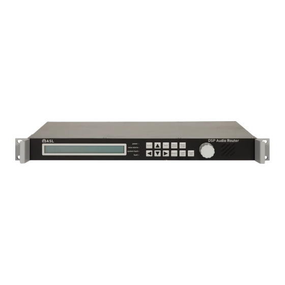
VAR4 / VAR12 / VAR20 - Operation Manual 2.1.2 Controls The front panel has membrane keys and a rotary encoder for entering commands and making selections, and a monitor loudspeaker. Figure 2 VAR Router Controls Table 3 VAR Router Front Panel Controls... -
Page 12: Access Code
VAR4 / VAR12 / VAR20 - Operation Manual 2.1.2.1 Access Code The VAR Router is password protected in order to prevent unauthorised alteration of the system configuration. Thus the system configuration cannot be changed unless the operator is ‘Logged on’ by entering the correct Access Code. -
Page 13: Responding To Fault Indications
VAR4 / VAR12 / VAR20 - Operation Manual Responding to Fault Indications Table 4 indicates the manual section to refer to in order to respond to fault indications. Table 4 Fault Indication Actions Action Section Logging on 4.2 Logging On Viewing Active Faults 20.1 Current Fault Status... -
Page 14: Navigating The Menus
VAR4 / VAR12 / VAR20 - Operation Manual Navigating the Menus The VAR Router menu system is very intuitive and, although the amount of information in this section is daunting, the user will find the menus largely self-explanatory. However, it is very important that the user reads the information contained in the following sections in its entirety as it contains notes on the safe configuration and operation of the system. -
Page 15: Changing An Option
VAR4 / VAR12 / VAR20 - Operation Manual 2.3.4 Changing an Option Use the keys and the rotary encoder to edit or scroll options. 2.3.5 Rotary Encoder The rotary encoder has multiple functions dependent on the current menu selection as follows: •... -
Page 16: Menu Map Of Functions
VAR4 / VAR12 / VAR20 - Operation Manual Menu Map of Functions sue: 03 complete, approved Page 16 of 308... - Page 17 VAR4 / VAR12 / VAR20 - Operation Manual Inputs [Mic/Line] [ANS] [DVA] [Misc] [Fall] [I/P #nn - MIC/LINE nn] [EVAC 01] [Music] [Mute] [Test Tone] [MIC/LINE nn] [Enabled] [Not Tol] [Unused] [Pri] [Class] [Gain] [O/pGains] [Name] [Music A] [Music B]...
-
Page 18: Typical Configuration Process
VAR4 / VAR12 / VAR20 - Operation Manual Typical Configuration Process Typical Configuration Process This checklist is provided to cover general aspects of system configuration. Note that some points may not This checklist is provided to cover general aspects of system configuration. Note that some points may not be applicable to the configuration of your system. - Page 19 VAR4 / VAR12 / VAR20 - Operation Manual Table 5 Configuration Checklist Check Refer to Configuration Task Page Section Access the VAR Router. Configure the required VAR Router parameters. Program the VAR Router for stand-alone or network operation. If the VAR Router is networked, program Fallback DVAs in the 5.1.3.11...
-
Page 20: Accessing The Var Router
VAR4 / VAR12 / VAR20 - Operation Manual Accessing the VAR Router Accessing the VAR Router The VAR Router is password protected in order to prevent unauthorised alteration of the system The VAR Router is password protected in order to prevent unauthorised alteration of the system configuration. -
Page 21: Logging On
VAR4 / VAR12 / VAR20 - Operation Manual Logging On The VAR Router provides two security levels by logging into the system using different access code. In order to log into the system proceed as follows. Select Configuration Access. Use the rotary encoder and/or arrow keys to enter the access code:... -
Page 22: Changing The System Access Code
VAR4 / VAR12 / VAR20 - Operation Manual Changing the System Access Code Changing the System Access Code The access code can only be changed if the user is logged onto the system with full access, i.e, as User 2. -
Page 23: Var Router Configuration
VAR Router Operation Mode The VAR12 and VAR20 Routers can operate in stand-alone or networked mode. The VAR4 can only operate in stand-alone mode, and should only be configured for this operation mode. In networked mode, the VAR12 and VAR20 Routers require a VAR-NIA Network Interface Adapter to interface to an Intellevac Network. - Page 24 VAR4 / VAR12 / VAR20 - Operation Manual • Not all Slave Unit Outputs have to be Network Outputs. On legacy 4x4 DAUs, all outputs need to be Network Outputs. − • Network Outputs do not have to be numbered in the same order as the Slave Ids and Slave Outputs, nor do they have to be contiguous (i.e.
-
Page 25: Setting The Var Router To Stand-Alone Operation
VAR4 / VAR12 / VAR20 - Operation Manual 5.1.2 5.1.2 Setting the VAR Router to Stand-alone Operation Setting the VAR Router to Stand-alone Operation In order to change the VAR Router from network mode settings to stand-alone mode, please follow the In order to change the VAR Router from network mode settings to stand-alone mode, please follow the instructions. -
Page 26: Mic/Line Inputs 1, 3 And 4 Type Configuration
VAR4 / VAR12 / VAR20 - Operation Manual 5.1.2.2 5.1.2.2 Mic/Line Inputs 1, 3 and 4 Type Configuration Mic/Line Inputs 1, 3 and 4 Type Configuration Mic/Line inputs 1, 3, and 4 should be set to ‘Unused’ in order to exclude the input from routing and audio Mic/Line inputs 1, 3, and 4 should be set to ‘Unused’... -
Page 27: Setting The Var Router To Network Operation
VAR4 / VAR12 / VAR20 - Operation Manual 5.1.3 5.1.3 Setting the VAR Router to Network Operation Setting the VAR Router to Network Operation In order to change the VAR Router from stand-alone mode settings to network mode, please follow the In order to change the VAR Router from stand-alone mode settings to network mode, please follow the instructions. -
Page 28: Mic/Line Input Configuration As Network Channel
VAR4 / VAR12 / VAR20 - Operation Manual Reference to Configuration Tool Reference to Configuration Tool 5.1.3.1 5.1.3.2 Mic/Line Input Configuration as Network Channel Check that the corresponding Mic/Line inputs are configured as Network Channels according to the number of channels set in the previous section. The following table describes the Mic/Line input allocation for network operation. -
Page 29: Network Channel Surveillance Tone Detection
VAR4 / VAR12 / VAR20 - Operation Manual 5.1.3.3 Network Channel Surveillance Tone Detection Ensure that the surveillance tone detection on the Network Channel is enabled and tone level is set to its default setting of –40dB in order to enable recovery in case of network faults. -
Page 30: Network Channel Equalisation Configuration
VAR4 / VAR12 / VAR20 - Operation Manual 5.1.3.4 Network Channel Equalisation Configuration Ensure that the relative gain for each frequency band (low, mid, and high frequencies) of the 3-band equaliser is set to its default setting of 0 dB, and the High Pass filter is disabled, as described in the following steps. -
Page 31: Network Channel Fade Up And Down Time Configuration
VAR4 / VAR12 / VAR20 - Operation Manual 5.1.3.5 Network Channel Fade Up and Down Time Configuration Ensure that the fade up/down times are set to their default setting of 00, as described in the following steps. Select Configuration System Router Inputs Mic/Line. -
Page 32: Network Channel Pre-Announcement Chime Configuration
VAR4 / VAR12 / VAR20 - Operation Manual 5.1.3.6 Network Channel Pre-announcement Chime Configuration The chimes of the network audio sources are set at the Audio Control Unit, so ensure that the chime is disabled at the local VAR Router. -
Page 33: Network Channel Input Gain And The Line Sensitivity Configuration
VAR4 / VAR12 / VAR20 - Operation Manual 5.1.3.7 Network Channel Input Gain and the Line Sensitivity Configuration Ensure that the input gain on the Network Channel is set to its default setting of –15 dB and sensitivity is set to ‘Line’, as described in the following steps. -
Page 34: Network Channel Relative Gain Configuration
VAR4 / VAR12 / VAR20 - Operation Manual 5.1.3.8 Network Channel Relative Gain Configuration Ensure that each output relative gain on the Network Channel is set to its default setting of 0 dB, as described in the following steps. Select Configuration System Router Inputs Mic/Line. -
Page 35: Network Channel Name Configuration
VAR4 / VAR12 / VAR20 - Operation Manual 5.1.3.9 Network Channel Name Configuration The name of the Network Channel inputs may be edited to reflect the actual use of the inputs. Note however that this is for reference only, and is shown in menu options to help the configuration process. - Page 36 VAR4 / VAR12 / VAR20 - Operation Manual Reference to Configuration Tool Reference to Configuration Tool 5.1.3.2 5.1.3.7 5.1.3.4 5.1.3.8 5.1.3.7 5.1.3.5 5.1.3.9 5.1.3.3 5.1.3.6 sue: 03 complete, approved Page 36 of 308 Page 36 of 308...
-
Page 37: Network Input Ambient Noise Sensor (Ans) Configuration
VAR4 / VAR12 / VAR20 - Operation Manual 5.1.3.10 Network Input Ambient Noise Sensor (ANS) Configuration As with local audio inputs on the Slave Units, it is possible to configure the ambient noise compensation to be applied to network inputs when they are routed to an output which is under the control of ambient noise sensors. - Page 38 VAR4 / VAR12 / VAR20 - Operation Manual Move to, and toggle to the required ANS tolerance option in the right field: Move to, and toggle to the required ANS tolerance option in the right field: Net-Ctrl MIC/LINE 1 Net-Ctrl MIC/LINE 1...
-
Page 39: Network Input Fallback
VAR4 / VAR12 / VAR20 - Operation Manual 5.1.3.11 Network Input Fallback It is important to define a local DVA input to act as a fallback for each of the emergency network DVAs in the event of network failure. These DVAs will be programmed with the same messages as the associated network DVAs. This will ensure that in case of a network failure during an emergency the emergency broadcast will continue, albeit no longer in synchronisation across the whole site. -
Page 40: Network Priority Configuration
VAR4 / VAR12 / VAR20 - Operation Manual 5.1.3.12 Network Priority Configuration The Slave Units arbitrate between the audio inputs into the Audio Control Unit, and their own local inputs according to the input priorities. Therefore in a networked system it is essential that the Slave Units are programmed so that they know the Priorities of the Audio Control Unit’s audio sources. -
Page 41: Var Id
VAR4 / VAR12 / VAR20 - Operation Manual VAR ID The VAR ID is used by the system to differentiate between different VAR Routers on the network. In order to configure the VAR ID proceed as follows. Select Configuration System Site VAR-ID. -
Page 42: System Date / Time
VAR4 / VAR12 / VAR20 - Operation Manual System Date / Time The VAR Router features a real time clock, which is used for time and date stamping of log entries such as fault reports. This is fitted with an internal Lithium battery so that the clock continues running without power applied. -
Page 43: Temperature
VAR4 / VAR12 / VAR20 - Operation Manual Temperature The VAR Router has an over-temperature alarm, and it is possible to configure the internal temperature at which this alarm is raised by following these steps. Select Configuration System Misc Temp. -
Page 44: Emergency Sounder Operation
VAR4 / VAR12 / VAR20 - Operation Manual Move to, and toggle to the required connection type in the right field: CTS disabled [Direct Connect] • Direct Connect Direct connection to PC. • Modem Connect Connection to PC via modem. - Page 45 VAR4 / VAR12 / VAR20 - Operation Manual • Fault Active Sounder: This output is suitable for driving an audible fault indicator. The output is deactivated if no faults are present, or if all faults have been acknowledged. − Therefore an audible indicator will be quiet.
-
Page 46: Host Protocol Configuration
VAR4 / VAR12 / VAR20 - Operation Manual Host Protocol Configuration The host protocol is the protocol used by a host system to interrogate and control the VAR Router over the RS232 communication port. This protocol follows a master/slave protocol, where the master is the host computer, and the slave is the VAR Router. -
Page 47: Fault Timeout Configuration
VAR4 / VAR12 / VAR20 - Operation Manual 5.9.2 Fault Timeout Configuration The Host Protocol Fault Timeout is the time the VAR Router waits for a message from the host system before generating a communication fault. It is possible to enable and to define the timeout, or to disable the fault reporting, as described in the following steps. -
Page 48: Password Control Configuration
VAR4 / VAR12 / VAR20 - Operation Manual 5.9.4 Password Control Configuration The host system connected to the VAR Router requires knowing the VAR Router’s access code, without this the VAR Router will not respond to commands from the host. Therefore it is possible to inhibit changes to the access code from the VAR Router’s front panel in order to prevent a user from inadvertently stopping the... - Page 49 VAR4 / VAR12 / VAR20 - Operation Manual Reference to Configuration Tool Reference to Configuration Tool Note that the system date and time cannot be modified through the Configuration Tool. Note that the system date and time cannot be modified through the Configuration Tool.
-
Page 50: Configuration Data
VAR4 / VAR12 / VAR20 - Operation Manual 5.10 5.10 Configuration Data Configuration Data Note that the configuration data functions are not available on the Configuration Tool. Note that the configuration data functions are not available on the Configuration Tool. -
Page 51: Var Router Software Versions
Scroll the list to display the version of each code on each board. [Board 0: CP 2.9.411] Where: Board 0: VAR4 base board CP, DSP, and EPLD software versions Board 1: VAR12 expansion board CP, DSP, and EPLD software versions Board 2: VAR20 expansion board CP, DSP, and EPLD software versions Default value: n.a. -
Page 52: Asl Amplifier Mainframe Commissioning
VAR4 / VAR12 / VAR20 - Operation Manual ASL Amplifier Mainframe Commissioning Please refer to the Amplifier Mainframe, Amplifier, and Interface Card user documentation to complement the information provided in the following sections. Detecting Frames Using ‘Learn’ Mode The ‘Learn’ function allows the system to automatically detect all ASL amplifier mainframes and amplifiers which are connected to the VAR Router. - Page 53 VAR4 / VAR12 / VAR20 - Operation Manual In the previous example, the display shows the data for mainframe 02, which has the following In the previous example, the display shows the data for mainframe 02, which has the following...
-
Page 54: Viewing Configured Mainframes
VAR4 / VAR12 / VAR20 - Operation Manual Viewing Configured Mainframes 6.2.1 Verbose View The verbose view provides a mainframe’s software version, as well as each amplifier’s software version number, power rating, and surveillance mode. In order to view the details of an amplifier mainframe proceed as follows. -
Page 55: Terse View
VAR4 / VAR12 / VAR20 - Operation Manual 6.2.2 Terse View The terse view provides a single list of configured mainframes with the amplifier power rating and surveillance mode compressed into a single line, in a similar fashion to how the data is displayed when ‘learn’... -
Page 56: Mainframe Commissioning
VAR4 / VAR12 / VAR20 - Operation Manual Mainframe Commissioning Mainframe Commissioning The act of commissioning after the ‘learn’ function has been performed commands the mainframe to The act of commissioning after the ‘learn’ function has been performed commands the mainframe to... -
Page 57: Editing/Viewing A Mainframe Description
VAR4 / VAR12 / VAR20 - Operation Manual 6.3.2 Editing/Viewing a Mainframe Description Each mainframe can be assigned a short description or name for ease of recognition. This description is for reference only, and is only shown in menus accessing mainframes, such as, mainframe commissioning and test menus. -
Page 58: Configuring A Mainframe Temperature Alarm
VAR4 / VAR12 / VAR20 - Operation Manual 6.3.3 Configuring a Mainframe Temperature Alarm Each mainframe can monitor its ambient temperature if required, and will then report a fault if the temperature exceeds the configured over-temperature alarm value. In order to configure the mainframe over-temperature monitoring proceed as follows. -
Page 59: Commissioning An Amplifier Slot
VAR4 / VAR12 / VAR20 - Operation Manual 6.3.4 Commissioning an Amplifier Slot Each amplifier mainframe houses up to four amplifiers, each inserted into one of the four available amplifier slots. These slots are referred to as Slot 1, Slot 2, Slot 3 and Slot 4 at the VAR Router. -
Page 60: Configuring An Amplifier's Internal Audio Path Ac Surveillance
VAR4 / VAR12 / VAR20 - Operation Manual 6.3.4.2 6.3.4.2 Configuring an Amplifier’s Internal Audio Path AC Surveillance Configuring an Amplifier’s Internal Audio Path AC Surveillance AC surveillance tone parameters should be configured for all amplifier surveillance card AC surveillance tone parameters should be configured for all amplifier surveillance card installed where AC surveillance is required, including all standby amplifiers. - Page 61 VAR4 / VAR12 / VAR20 - Operation Manual Scroll the surveillance frequency range until the required option is displayed: [No Surv] • No Surv No AC surveillance. This setting is used when the Amplifier Interface Card does not provide AC surveillance, e.g., the ASL NSINT Non-Surveyed Interface Card.
-
Page 62: Configuring An Amplifier's Ac Surveillance Thresholds
VAR4 / VAR12 / VAR20 - Operation Manual 6.3.4.2.2 Configuring an Amplifier’s AC Surveillance Thresholds The surveillance thresholds are used by the amplifier surveillance cards to monitor the amplifier’s health when the AC surveillance is enabled, as described in Section “6.3.4.2.1 Configuring an Amplifier’s AC... - Page 63 VAR4 / VAR12 / VAR20 - Operation Manual Note: In an ASL system with the surveillance tone level set to its default level of –12dB, the typical Note: In an ASL system with the surveillance tone level set to its default level of –12dB, the typical...
-
Page 64: Configuring An Amplifier's Ac Surveillance Interval
VAR4 / VAR12 / VAR20 - Operation Manual 6.3.4.2.3 Configuring an Amplifier’s AC Surveillance Interval As standard the VAR Router output is configured to generate a pulsed surveillance tone, as described in Section “12.4 Surveillance Tone Generation Configuration”. The maximum interval between surveillance tone pulses for pulsed surveillance tones can be configured. -
Page 65: Configuring An Loudspeaker Line Dc Surveillance
VAR4 / VAR12 / VAR20 - Operation Manual 6.3.4.3 6.3.4.3 Configuring an Loudspeaker Line DC Surveillance Configuring an Loudspeaker Line DC Surveillance The loudspeaker line integrity monitoring is carried out using DC surveillance from the appropriate amplifier. The loudspeaker line integrity monitoring is carried out using DC surveillance from the appropriate amplifier. - Page 66 VAR4 / VAR12 / VAR20 - Operation Manual If ‘Surveyed’ has been selected, configure the number of EOL resistors on the loudspeaker line by If ‘Surveyed’ has been selected, configure the number of EOL resistors on the loudspeaker line by...
-
Page 67: Configuring An Loudspeaker Line Earth Leakage Monitoring
VAR4 / VAR12 / VAR20 - Operation Manual 6.3.4.4 Configuring an Loudspeaker Line Earth Leakage Monitoring The loudspeaker line connected to an amplifier can be monitored for resistance to earth by an ASL LSDIC or LSDDC Surveillance Interface Card. An earth leakage fault will be reported when the measured resistance is below the threshold value. -
Page 68: Mainframe Learn Check
VAR4 / VAR12 / VAR20 - Operation Manual 6.3.5 Mainframe Learn Check As standard the VAR Router is configured to check if the ‘Learn’ function has been performed following a power cycle or a fault clearance. If no mainframes are configured at all, then a fault will be raised. This is to prevent the ‘Learn’... - Page 69 VAR4 / VAR12 / VAR20 - Operation Manual Reference to Configuration Tool Reference to Configuration Tool Note that Amplifier Mainframe control functions are not available on the Configuration Tool, except for the Note that Amplifier Mainframe control functions are not available on the Configuration Tool, except for the “Frame Learn Check”...
-
Page 70: Mic/Line Input Configuration
VAR4 / VAR12 / VAR20 - Operation Manual Mic/Line Input Configuration Dependent on model, the VAR Router has 4,12 or 20 electronically balanced universal inputs, these have switchable sensitivity to accept microphone or line level signals, and have digitally controlled adjustable analogue gain prior to the DSP. - Page 71 VAR4 / VAR12 / VAR20 - Operation Manual Table 7 VAR Router Mic/Line Input Capabilities Inputs Available Input Types Microphone Buttons VAR Router Applicability ASL Fire Microphone ASL Zoned Fire Microphone microphone buttons configurable for zone select, DVA VAR4, VAR12, or VAR20 ASL Paging Microphone routing, all call, or route reset.
- Page 72 VAR4 / VAR12 / VAR20 - Operation Manual Table 8 Configurable Mic/Line Input Parameters Phantom Input Type Surv Fade Chime Gain Class Name Buttons Gains Power Fire Microphone Zoned Fire Microphone Paging Microphone Single Button Microphone Miscellaneous 1) PTT button is configurable for zone selection.
-
Page 73: Mic/Line Input Type Configuration
VAR4 / VAR12 / VAR20 - Operation Manual Mic/Line Input Type Configuration In order to configure the type of the audio source connected to a Mic/Line input proceed as follows. Select Configuration System Router Inputs Mic/Line. Scroll the Mic/Line input list and select the required input: [I/P #01 –... - Page 74 VAR4 / VAR12 / VAR20 - Operation Manual Reference to Configuration Tool Reference to Configuration Tool Type List Mic/Line Input List sue: 03 complete, approved Page 74 of 308 Page 74 of 308...
-
Page 75: Parameters Common To All Mic/Line Input Types
VAR4 / VAR12 / VAR20 - Operation Manual Parameters Common to All Mic/Line Input Types 7.2.1 Input Surveillance Tone Detection Configuration The VAR Router is able to detect the presence of a low frequency surveillance tone, nominally 20Hz, on the Mic/Line inputs. - Page 76 VAR4 / VAR12 / VAR20 - Operation Manual Move to, and toggle to the required surveillance tone detection option in the left field: Move to, and toggle to the required surveillance tone detection option in the left field: [Mode=Off] Level(dB)=-40 [Mode=Off] Level(dB)=-40 •...
-
Page 77: Input Equalisation Configuration
VAR4 / VAR12 / VAR20 - Operation Manual 7.2.2 Input Equalisation Configuration A 3-band equaliser is provided on Mic/Line inputs in order to balance the input tone. This equaliser has a shelving HF (treble) adjustment, shelving LF (bass) adjustment, and a fixed MID section adjustment. - Page 78 VAR4 / VAR12 / VAR20 - Operation Manual Move to, and scroll the low frequency band gains until the required value is displayed: [LF= 0] Mid= 0 HF= 0 HPFilter=On Default value: ‘0’ Possible values: –12dB to +12dB (1dB steps) Note: This should be set to ‘0dB’...
-
Page 79: Input Fade Up And Down Time Configuration
VAR4 / VAR12 / VAR20 - Operation Manual 7.2.3 Input Fade Up and Down Time Configuration It is possible to specify a fade up and fade down time for each Mic/Line input or Music input. This can be set to provide the desired changeover fading, e.g. when a broadcast interrupts background music, or a lower priority broadcast. - Page 80 VAR4 / VAR12 / VAR20 - Operation Manual Figure 6 Sequence of Events for Paging Microphone Chime Overriding a Background Music MUSIC AUDIO MUSIC AUDIO MUSIC FADE UP=T1 FADE DOWN= T2 MICROPHONE MIC AUDIO CHIME AUDIO MICROPHONE FADE UP=T3 FADE DOWN= T4...
- Page 81 VAR4 / VAR12 / VAR20 - Operation Manual Move to, and select the Audio menu item, which is shown in different positions for different input types as follows: ‘Paging Microphone’ and ‘Zoned Fire Microphone’ Buttons [Audio] Ctrl Name ‘Single Button Microphone’...
-
Page 82: Input Pre-Announcement Chime Configuration
VAR4 / VAR12 / VAR20 - Operation Manual 7.2.4 Input Pre-announcement Chime Configuration A pre-announcement chime may be configured to any Mic/Line input. If configured, then the chime will be triggered when the input source is routed. However the actual audio input will only be routed when the chime is complete. - Page 83 VAR4 / VAR12 / VAR20 - Operation Manual Move to, and scroll the chime type list until the required type is displayed in the left field: [Type=Off] LEVEL(dB)-12 • [Type=Off] No pre-announcement chime, e.g. when the Mic/Line input is used for background music.
-
Page 84: Input Gain And The Line Sensitivity Configuration
VAR4 / VAR12 / VAR20 - Operation Manual 7.2.5 Input Gain and the Line Sensitivity Configuration The Mic/Line inputs have switchable sensitivity in order to accept microphone or line level signals, and have adjustable analogue gain analogue. The analogue gain settings are non-volatile, are and retained even after power failure and/or processor failure. - Page 85 VAR4 / VAR12 / VAR20 - Operation Manual Move to, and scroll the possible input gains until the required value is displayed in the left field: [Gain(dB)=-14] Sens.=Line Default value: ‘–14’ (‘–20’ for Miscellaneous Input) Possible values: –63dB to 0dB (1dB steps) Note: The input gain of each audio input should normally be set so that all inputs are balanced, and give the same output level on each of the outputs.
-
Page 86: Input Relative Gain Configuration
VAR4 / VAR12 / VAR20 - Operation Manual 7.2.6 Input Relative Gain Configuration Normally all input gains will be set to ‘balance’ each of the inputs, and the output gain will be set to give the required level at each output. However, if any input is desired to have a different gain in a particular output or outputs, then these inputs can be given a different gain relative to each appropriate output. - Page 87 VAR4 / VAR12 / VAR20 - Operation Manual Move to, and scroll the output list until the required output is displayed in the left field: [OUTPUT 01] Gain(dB)= Default value: output 1 name Outputs: 4 output for VAR4 12 output for VAR12...
-
Page 88: Input Priority Configuration
VAR4 / VAR12 / VAR20 - Operation Manual 7.2.7 Input Priority Configuration The input priority is used to resolve conflicts when two or more inputs try to broadcast to the same output. In this case the input with the highest priority will be able to broadcast, and the others will not. - Page 89 VAR4 / VAR12 / VAR20 - Operation Manual Move to, and select the Pri menu item. Move to, and select the Pri menu item. [Pri] Phantom [Pri] Phantom Class Class Move to, and scroll the output list until the required output is displayed in the left field:...
-
Page 90: Input Phantom Power Configuration
VAR4 / VAR12 / VAR20 - Operation Manual 7.2.8 Input Phantom Power Configuration It is possible to select whether phantom power is applied to a Mic/Line input, as described in the following steps. This is typically used for Electret and Condenser microphones. -
Page 91: Input Emergency Class
VAR4 / VAR12 / VAR20 - Operation Manual 7.2.9 Input Emergency Class The emergency class is used to control the VAR Router’s Remote Fault Output when configured for ‘Emergency DVA Active Indicator’ as follows: • The output is activated if an emergency audio input, e.g. ALERT or EVACUATE DVAs, is routed to an output. - Page 92 VAR4 / VAR12 / VAR20 - Operation Manual Scroll until the required classification for the microphone is displayed: Scroll until the required classification for the microphone is displayed: [Non Emergency] [Non Emergency] • • [Non Emergency] [Non Emergency] The input source has a non-emergency priority, e.g. Paging Microphones and music.
-
Page 93: Input Name Configuration
VAR4 / VAR12 / VAR20 - Operation Manual 7.2.10 Input Name Configuration The name of any audio input source may be edited to reflect the actual use of the input. This is for reference only, and it is shown in input related menu options. -
Page 94: Input Ambient Noise Sensor (Ans) Configuration
VAR4 / VAR12 / VAR20 - Operation Manual 7.2.11 Input Ambient Noise Sensor (ANS) Configuration Ambient noise compensation is applied to outputs, however it is possible to configure the ambient noise compensation to be applied to any particular input routed to an output which has ANS compensation enabled. - Page 95 VAR4 / VAR12 / VAR20 - Operation Manual Move to, and toggle to the required ANS tolerance option in the right field: MIC/LINE 01 Enabled [Not Tol] • [Not Tol] The ANS system is not tolerant to this input, i.e. the ANS sensing is stopped while this input is routed.
-
Page 96: Local Fallback Configuration
VAR4 / VAR12 / VAR20 - Operation Manual 7.2.12 Local Fallback Configuration It is possible to define a local audio input, typically a DVA, to act as a fallback to local microphone inputs. The fallback audio source is used if the original audio source is unavailable for any reason. - Page 97 VAR4 / VAR12 / VAR20 - Operation Manual Reference to Configuration Tool Reference to Configuration Tool 7.2.8 7.2.1 7.2.9 7.2.2 7.2.5 7.2.6 7.2.11 7.2.3 7.2.10 7.2.1 7.2.4 sue: 03 complete, approved Page 97 of 308 Page 97 of 308...
-
Page 98: Paging Microphone And Zoned Fire Microphone Specifics
VAR4 / VAR12 / VAR20 - Operation Manual Paging Microphone and Zoned Fire Microphone Specifics 7.3.1 PTT Button Configuration The PTT button may be configured just to act as a Push To Talk on zones selected by other buttons, or it may be configured so that when pressed without a prior zone selection then it acts as an All-Call button functioning as ‘select all zones’... - Page 99 VAR4 / VAR12 / VAR20 - Operation Manual Move to, and toggle to the required restore option in the right field: Move to, and toggle to the required restore option in the right field: All Call Disabled [Restore Disabled] All Call Disabled [Restore Disabled] •...
-
Page 100: Ptt Button Cough Timeout Configuration
VAR4 / VAR12 / VAR20 - Operation Manual 7.3.2 PTT Button Cough Timeout Configuration The cough timeout is the time length the PTT button may be released before the route is closed down. When this is enabled, the audio path is muted immediately when the PTT button is released, allowing the operator to cough without it being broadcast. - Page 101 VAR4 / VAR12 / VAR20 - Operation Manual Reference to Configuration Tool Reference to Configuration Tool 7.3.2 sue: 03 complete, approved oved Page 101 of 308 Page 101 of 308...
-
Page 102: Listen-In Configuration
VAR4 / VAR12 / VAR20 - Operation Manual 7.3.3 Listen-in Configuration The VAR Router is capable to provide a mixed ‘listen-in’ output. A specially assigned button or key-switch may be configured for controlling the 'listen-in' function on microphones provided with ‘listen-in’ button or key switch. One example of this is the ‘listen-in’ button on the ASL Station Master Console (SMC) microphones. - Page 103 VAR4 / VAR12 / VAR20 - Operation Manual In order to configure a button or key-switch on a microphone as ‘listen-in’ button proceed as follows. In order to configure a button or key-switch on a microphone as ‘listen-in’ button proceed as follows.
- Page 104 VAR4 / VAR12 / VAR20 - Operation Manual Move to, and scroll the configuration options for the selected switch until the required option is displayed Move to, and scroll the configuration options for the selected switch until the required option is displayed...
-
Page 105: Microphone Button Configuration
VAR4 / VAR12 / VAR20 - Operation Manual 7.3.4 7.3.4 Microphone Button Configuration Microphone Button Configuration Buttons on Paging Microphone or a Zoned Fire Microphone may be configured as either: Buttons on Paging Microphone or a Zoned Fire Microphone may be configured as either: •... -
Page 106: Configuring A Button As Unused
VAR4 / VAR12 / VAR20 - Operation Manual 7.3.4.1 7.3.4.1 Configuring a Button as Unused Configuring a Button as Unused Any button that is not in use should be configured as unused, to prevent inadvertent operation. Any button that is not in use should be configured as unused, to prevent inadvertent operation. - Page 107 VAR4 / VAR12 / VAR20 - Operation Manual Move to, and scroll the option list until the ‘Not-Conf’ (not configured, i.e., unused) option is displayed in the middle field: Button #01 [Not-conf] Security Other options available: • [MIC Routing] Configures the selected button for zone selection (routing).
- Page 108 VAR4 / VAR12 / VAR20 - Operation Manual Reference to Configuration Tool Reference to Configuration Tool 7.3.4.1 sue: 03 complete, approved oved Page 108 of 308 Page 108 of 308...
-
Page 109: Configuring A Button For Microphone Routing (Zone Selection)
VAR4 / VAR12 / VAR20 - Operation Manual 7.3.4.2 Configuring a Button for Microphone Routing (Zone Selection) The Microphone Routing button function is for zone selection, i.e. when pressed it selects a specified output or group of outputs to which the microphone audio is to be routed when PTT button subsequently is pressed. - Page 110 VAR4 / VAR12 / VAR20 - Operation Manual Move to, and scroll the option list until the ‘Mic Routing’ option is displayed in the middle field: Button #01 [Mic Routing] Security Other options available: • [Not-Conf] The button is not used.
- Page 111 VAR4 / VAR12 / VAR20 - Operation Manual Reference to Configuration Tool Reference to Configuration Tool Configured Zones 7.3.4.2 sue: 03 complete, approved oved Page 111 of 308 Page 111 of 308...
-
Page 112: Configuring A Button For Dva Routing/Other Input Routing
VAR4 / VAR12 / VAR20 - Operation Manual 7.3.4.3 7.3.4.3 Configuring a Button for DVA Routing/Other Input Routing Configuring a Button for DVA Routing/Other Input Routing ‘DVA Routing’ is only available for Paging or Zoned Fire Microphones that are connected to ‘DVA Routing’... - Page 113 VAR4 / VAR12 / VAR20 - Operation Manual The configured Mic/Line type is displayed. The input type may be changed, as described in Section “7.1 Mic/Line Input Type Configuration”. Press the SELECT key to display the next sub-menu. Move to, and select the Buttons menu item.
- Page 114 VAR4 / VAR12 / VAR20 - Operation Manual Reference to Configuration Tool Reference to Configuration Tool 7.3.4.3 sue: 03 complete, approved oved Page 114 of 308 Page 114 of 308...
-
Page 115: Configuring The Route For A Dva Routing Button
VAR4 / VAR12 / VAR20 - Operation Manual 7.3.4.3.1 Configuring the Route for a DVA Routing Button Once a button is configured for ‘DVA Routing’, it is necessary to define the route or routes that it controls, by associating an input to each available output, as described in the following steps. - Page 116 VAR4 / VAR12 / VAR20 - Operation Manual 11. Move to, and scroll the right field list until the required input is displayed: OUTPUT 01 [Not Conf] • [Not-Conf] No input associated with the particular output. The output is not affected by this DVA Routing button.
- Page 117 VAR4 / VAR12 / VAR20 - Operation Manual Reference to Configuration Tool Reference to Configuration Tool 7.3.4.3.1 sue: 03 complete, approved oved Page 117 of 308 Page 117 of 308...
-
Page 118: Configuring A Dva Routing Button For Non-Latching Mode
VAR4 / VAR12 / VAR20 - Operation Manual 7.3.4.3.2 Configuring a DVA Routing Button for Non-latching Mode This mode is useful for the control of both DVA routes and other sources, such as background music. When configured for non-latching operation the first press of a ‘DVA Routing’ button initiates a route, and the second press terminates it. - Page 119 VAR4 / VAR12 / VAR20 - Operation Manual 11. Move to, and scroll the mode list until the ‘Mode=Not Latched’ mode is displayed in the left field: 11. Move to, and scroll the mode list until the ‘Mode=Not Latched’ mode is displayed in the left field:...
-
Page 120: Configuring A Dva Routing Button For Latching Mode
VAR4 / VAR12 / VAR20 - Operation Manual 7.3.4.3.3 Configuring a DVA Routing Button for Latching Mode This mode is normally used for emergency DVA message routes, but can also be of use for routing other inputs. When configured for latching operation pressing a ‘DVA Routing’ button initiates a route; and pressing the associated reset button terminates it. - Page 121 VAR4 / VAR12 / VAR20 - Operation Manual 11. Move to, and scroll the mode list until the ‘Mode=Latched’ mode is displayed in the left field: [Mode=Latched] ResetButton -- When this mode is selected, the reset button list on the right side is scrollable for selection.
- Page 122 VAR4 / VAR12 / VAR20 - Operation Manual Reference to Configuration Tool Reference to Configuration Tool 7.3.4.3.2 sue: 03 complete, approved oved Page 122 of 308 Page 122 of 308...
-
Page 123: Configuring A Dva Routing Button For Play Once Mode
VAR4 / VAR12 / VAR20 - Operation Manual 7.3.4.3.4 Configuring a DVA Routing Button for Play Once Mode This mode is only used for the control of DVA routes. When configure for ‘Play Once’ mode, pressing a ‘DVA Routing’ button plays the DVAs associated with the route once only. - Page 124 VAR4 / VAR12 / VAR20 - Operation Manual 11. Move to, and scroll the mode list until the ‘Mode=Play Once’ mode is displayed in the left field: 11. Move to, and scroll the mode list until the ‘Mode=Play Once’ mode is displayed in the left field:...
-
Page 125: Dva Routing Button Busy Indication Configuration
VAR4 / VAR12 / VAR20 - Operation Manual 7.3.4.3.5 DVA Routing Button Busy Indication Configuration It is also possible to configure whether or not the route associated with a ‘DVA Routing’ button should cause a busy indication on the LEDs associated with microphone zone select buttons. If for instance this routing were used for background music control, then the busy LEDs would not be lit. - Page 126 VAR4 / VAR12 / VAR20 - Operation Manual 10. Move and toggle to the required busy indication option in the middle field: 10. Move and toggle to the required busy indication option in the middle field: Latching [Busy=On] DVA-Full Latching [Busy=On] DVA-Full •...
-
Page 127: Dva Routing Button Dva Play Mode Configuration
VAR4 / VAR12 / VAR20 - Operation Manual 7.3.4.3.6 DVA Routing Button DVA Play Mode Configuration This setting is only relevant when a ‘DVA Routing’ button is used for control of DVA routes. The DVAs assigned to a button may be configured to cease playing immediately that the route is terminated (DVA-Part), or play until the end of the message and then stop (DVA-Full). - Page 128 VAR4 / VAR12 / VAR20 - Operation Manual 10. Move to, and toggle to the required play mode in the right field: 10. Move to, and toggle to the required play mode in the right field: Latching Latching Busy=On [DVA-Full] Busy=On [DVA-Full] •...
-
Page 129: Clearing The Route Associated With A Dva Routing Button
VAR4 / VAR12 / VAR20 - Operation Manual 7.3.4.3.7 Clearing the Route Associated with a DVA Routing Button When re-configuring the route associated to a ‘DVA Routing’ button, the user has the option to clear down the route associated with a ‘DVA Routing’ button at once, as described in the following steps. -
Page 130: Configuring A Button As An All-Call Button
VAR4 / VAR12 / VAR20 - Operation Manual 7.3.4.4 Configuring a Button as an All-Call Button The button function is ‘select all zones’. When the button is pressed, all outputs, which have been configured as being affected by any zone selection buttons on the microphone, are selected for broadcast from the microphone, i.e. - Page 131 VAR4 / VAR12 / VAR20 - Operation Manual Move to, and scroll the option list until the ‘AllCall’ option is displayed in the middle field: Button #01 [AllCall] Security Other options available: • [Not-Conf] Button is not used. See Section “7.3.4.1 Configuring a Button as...
- Page 132 VAR4 / VAR12 / VAR20 - Operation Manual Reference to Configuration Tool Reference to Configuration Tool 7.3.4.4 Configured Zones sue: 03 complete, approved oved Page 132 of 308 Page 132 of 308...
-
Page 133: Security Key-Switch Configuration
VAR4 / VAR12 / VAR20 - Operation Manual 7.3.4.5 Security Key-switch Configuration Security key-switches can be configured to protect the operation of any microphone button. When a button is protected, then the security key must be turned on for the button function to be allowed. - Page 134 VAR4 / VAR12 / VAR20 - Operation Manual Move to, and toggle to the required protection mode in the left field: Move to, and toggle to the required protection mode in the left field: [Mode=Not Protected] Switch #-- [Mode=Not Protected] Switch #-- •...
-
Page 135: Single Button Microphone Specific Configuration
VAR4 / VAR12 / VAR20 - Operation Manual Single Button Microphone Specific Configuration 7.4.1 PTT Button Zone Selection Configuration The PTT button of a Single Button Microphone may be configured to broadcast a single output, or a group of outputs. Pressing the PTT button will then cause the microphone audio to be routed to the programmed zone selection. - Page 136 VAR4 / VAR12 / VAR20 - Operation Manual Move to, and toggle to the required selection option in the right field: Move to, and toggle to the required selection option in the right field: OUTPUT 01 [Not Selected] OUTPUT 01 [Not Selected] •...
-
Page 137: Ptt Button Cough Timeout Configuration
VAR4 / VAR12 / VAR20 - Operation Manual 7.4.2 PTT Button Cough Timeout Configuration The cough timeout is the time length the PTT button may be released before the route is closed down. When this is enabled, the audio path is muted immediately when the PTT button is released, allowing the operator to cough without it being broadcast. - Page 138 VAR4 / VAR12 / VAR20 - Operation Manual Reference to Configuration Tool Reference to Configuration Tool 7.4.2 sue: 03 complete, approved oved Page 138 of 308 Page 138 of 308...
-
Page 139: Dva Input Configuration
VAR4 / VAR12 / VAR20 - Operation Manual DVA Input Configuration The VAR Router includes digital storage for up to twelve Digital Voice Announcer (DVA) messages. Theser are in two types: Long DVA messages (32 seconds) and Short DVA messages (16 seconds): •... -
Page 140: Dva Input Relative Gain Configuration
VAR4 / VAR12 / VAR20 - Operation Manual DVA Input Relative Gain Configuration Normally all DVA input gains will be set to ‘balance’ each of the inputs, and the output gain will be set to give the required level at each output. However, if any DVA input is desired to have a different gain in a particular output or outputs, then these inputs can be given a different gain relative to each appropriate output. -
Page 141: Dva Input Priority Configuration
VAR4 / VAR12 / VAR20 - Operation Manual DVA Input Priority Configuration The input priority is used to resolve conflicts when two or more inputs try to broadcast to the same output. In this case the input with the highest priority will be able to broadcast, and the others will not. - Page 142 VAR4 / VAR12 / VAR20 - Operation Manual Scroll the input source priority list until the priority which is to be applied to the selected output is Scroll the input source priority list until the priority which is to be applied to the selected output is...
-
Page 143: Dva Input Emergency Class
VAR4 / VAR12 / VAR20 - Operation Manual DVA Input Emergency Class The emergency class is used to control the VAR Router’s Remote Fault Output when configured for ‘Emergency DVA Active Indicator’ as follows: • The output is activated if an emergency audio input, e.g. ALERT or EVACUATE DVAs, is routed to an output. - Page 144 VAR4 / VAR12 / VAR20 - Operation Manual In order to modify an input class proceed as follows. In order to modify an input class proceed as follows. Select Configuration System Router Inputs DVA. Select Configuration System Router Inputs DVA.
-
Page 145: Dva Input Name Configuration
VAR4 / VAR12 / VAR20 - Operation Manual DVA Input Name Configuration The name of any DVA input may be edited to reflect the actual use of the input, as described in the following steps. This is for reference only, and is shown in DVA or input related menu options. -
Page 146: Dva Input Ambient Noise Sensor (Ans) Configuration
VAR4 / VAR12 / VAR20 - Operation Manual DVA Input Ambient Noise Sensor (ANS) Configuration Ambient noise compensation is applied to outputs, however it is possible to configure the ambient noise compensation to be applied to any particular input routed to an output which has ANS compensation enabled. - Page 147 VAR4 / VAR12 / VAR20 - Operation Manual Move to, and toggle to the required ANS tolerance option in the right field: Move to, and toggle to the required ANS tolerance option in the right field: MIC/LINE 01 MIC/LINE 01...
-
Page 148: Background Music Configuration
VAR4 / VAR12 / VAR20 - Operation Manual Background Music Configuration The VAR Router provides two music inputs: Music A, and Music B, of which either one can be used at any time, with Music A selected by default. Only one music input can be routed at a time. -
Page 149: Music Input Configuration
VAR4 / VAR12 / VAR20 - Operation Manual Music Input Configuration 9.1.1 Music Input Equalisation Configuration A 3-band equaliser is provided on each of the Music inputs (Music A and Music B) in order to balance the input tone. This equaliser has a shelving HF (treble) adjustment, shelving LF (bass) adjustment, and a fixed MID section adjustment. -
Page 150: Music Input Fade Up And Down Time Configuration
VAR4 / VAR12 / VAR20 - Operation Manual 9.1.2 Music Input Fade Up and Down Time Configuration It is possible to specify a fade up and fade down time for the Music inputs. This can be set to provide the desired changeover fading, e.g. - Page 151 VAR4 / VAR12 / VAR20 - Operation Manual Figure 8 Sequence of Events for Paging Microphone Chime Overriding a Background Music MUSIC AUDIO MUSIC AUDIO MUSIC FADE UP=T1 FADE DOWN= T2 MICROPHONE MIC AUDIO CHIME AUDIO MICROPHONE FADE UP=T3 FADE DOWN= T4...
-
Page 152: Music Input Gain Configuration
VAR4 / VAR12 / VAR20 - Operation Manual 9.1.3 Music Input Gain Configuration Each of Music inputs (Music A and Music B) has adjustable analogue gain analogue. The analogue gain settings are non-volatile, are and retained even after power failure and/or processor failure. -
Page 153: Music Input Relative Gain Configuration
VAR4 / VAR12 / VAR20 - Operation Manual 9.1.4 Music Input Relative Gain Configuration Normally all Music input gains will be set to ‘balance’ the input, and the output gain will be set to give the required level at each output. However, if the Music input is desired to have a different gain in a particular output or outputs, then these inputs can be given a different gain relative to each appropriate output. -
Page 154: Music Input Priority Configuration
VAR4 / VAR12 / VAR20 - Operation Manual 9.1.5 9.1.5 Music Input Priority Configuration Music Input Priority Configuration The input priority is used to resolve conflicts when two or more inputs try to broadcast to the same output. In The input priority is used to resolve conflicts when two or more inputs try to broadcast to the same output. In this case the input with the highest priority will be able to broadcast, and the others will not. -
Page 155: Music Input Emergency Class
VAR4 / VAR12 / VAR20 - Operation Manual 9.1.6 Music Input Emergency Class The emergency class is used to indicate the emergency DVA message status, as described in Section “8.4 DVA Input Emergency Class”. The emergency class will be applied to the routed Music input be it either Music A, or Music B. -
Page 156: Music Input Ambient Noise Sensor (Ans) Configuration
VAR4 / VAR12 / VAR20 - Operation Manual 9.1.8 Music Input Ambient Noise Sensor (ANS) Configuration Ambient noise compensation is applied to outputs, however it is possible to configure the ambient noise compensation to be applied to any particular input routed to an output which has ANS compensation enabled. - Page 157 VAR4 / VAR12 / VAR20 - Operation Manual Move to, and toggle to the required ANS tolerance option in the right field: Move to, and toggle to the required ANS tolerance option in the right field: MIC/LINE 01 MIC/LINE 01...
-
Page 158: Contact Music Selector Configuration
VAR4 / VAR12 / VAR20 - Operation Manual Contact Music Selector Configuration Although the VAR Router provides two music inputs Music A and Music B. Only one can be routed at a time, Music A being routed by default. Where switchable music sources are required, it is possible to assign a contact input to act as a Music Selector , and to switch between Music A and Music B, as described in the following steps. - Page 159 VAR4 / VAR12 / VAR20 - Operation Manual Reference to Configuration Tool Reference to Configuration Tool sue: 03 complete, approved oved Page 159 of 308 Page 159 of 308...
-
Page 160: Mute Input Configuration
VAR4 / VAR12 / VAR20 - Operation Manual Mute Input Configuration The Mute input is a special input, which mutes even fire microphones if needed. For this purpose its priority is set to ‘0’ by default. However, the mute input is configurable, so it is possible to mute just DVAs, and/or any other inputs on a priority basis. -
Page 161: Mute Input Priority Set-Up
VAR4 / VAR12 / VAR20 - Operation Manual 10.2 10.2 Mute Input Priority Set-up Mute Input Priority Set-up Note that the default priority is 00 in order to mute even fire microphones. It is possible to set a lower priority Note that the default priority is 00 in order to mute even fire microphones. - Page 162 VAR4 / VAR12 / VAR20 - Operation Manual Reference to Configuration Tool Reference to Configuration Tool 10.2 10.1 sue: 03 complete, approved oved Page 162 of 308 Page 162 of 308...
-
Page 163: Test Tone Input Configuration
VAR4 / VAR12 / VAR20 - Operation Manual Test Tone Input Configuration Test Tone Input Configuration Test Tones are available on VAR Router SW V4.1.070 or later, and requires DSP SW V3.1.632 Test Tones are available on VAR Router SW V4.1.070 or later, and requires DSP SW V3.1.632 or later. -
Page 164: Test Tone Type Configuration
VAR4 / VAR12 / VAR20 - Operation Manual 11.1 Test Tone Type Configuration In order to select the Test Tone type which will be generated proceed as follows. Select Configuration System Router Inputs Misc Test Tone. Move to, and scroll the Test Tone types until the required type is displayed in the left field:... -
Page 165: Test Tone Input Priority Set-Up
VAR4 / VAR12 / VAR20 - Operation Manual 11.3 11.3 Test Tone Input Priority Set-up Test Tone Input Priority Set-up Setting a priority lower than any other audio source enables the Test Tone to be indefinitely routed without Setting a priority lower than any other audio source enables the Test Tone to be indefinitely routed without preventing microphone, and DVA message inputs from overriding it. - Page 166 VAR4 / VAR12 / VAR20 - Operation Manual Reference to Configuration Tool Reference to Configuration Tool 11.3 11.1 11.2 sue: 03 complete, approved oved Page 166 of 308 Page 166 of 308...
-
Page 167: Output Configuration
VAR4 / VAR12 / VAR20 - Operation Manual Output Configuration Induction Loop outputs are supported by VAR Router V4.1.0470 or later. As standard, all outputs are standard outputs, unless the VAR Router is configured to support Induction Loops, as described in Section “13.1 Setting the VAR Router to Support Induction... -
Page 168: Equalisation Configuration
VAR4 / VAR12 / VAR20 - Operation Manual 12.2 Equalisation Configuration The 8-band equaliser can be configured for each output. This operates on the frequencies: 125Hz, 250Hz, 500Hz, 1kHz, 2kHz, 6kHz, 8kHz, and 16kHz. Equalisation of each output may be useful to obtain the best possible audio performance, given the specific loudspeaker installation surface finishes, and shape of the zone. - Page 169 VAR4 / VAR12 / VAR20 - Operation Manual Move to, and scroll the possible gains until the required value is displayed in the right field: 125Hz [ Default value: ‘0’ Possible values: −12 to +12dB (1dB steps) Repeat steps to set the gain for each band.
-
Page 170: Ambient Noise Sensor (Ans) Configuration
VAR4 / VAR12 / VAR20 - Operation Manual 12.3 Ambient Noise Sensor (ANS) Configuration An Ambient Noise Sensor (ANS), or multiple ANS sensors, may be used to adjust the output gain of any zone based on a measure of the ambient noise in the target zone, see Section “16.2.5 Configuring an... - Page 171 VAR4 / VAR12 / VAR20 - Operation Manual Figure 9 ANS Operation Example AMBIENT NOISE LEVEL ANS=+90dBA MAX CONTROL RANGE (+20dB) ANS=+70dBA AREA AMBIENT NOISE BELOW MIN ANS THRESHOLD, THEREFORE MINiMUM GAIN IS USED. AREA ANNOUNCEMENT AMBIENT NOISE ABOVE MAX ANS THRESHOLD, IN PROGRESS THEREFORE MAXIMUM GAIN IS USED.
-
Page 172: Enabling/Disabling The Ans And Setting The Attack Time
VAR4 / VAR12 / VAR20 - Operation Manual 12.3.1 Enabling/Disabling the ANS and Setting the Attack Time In order to enable or disable the ANS sensor from controlling an output, proceed as follows. Select Configuration System Router Outputs. From V4.1.0470 or later, move to, and select the Configuration menu item. -
Page 173: Configuring The Ans Range
VAR4 / VAR12 / VAR20 - Operation Manual 12.3.2 Configuring the ANS Range Three types of ASL Ambient Noise Sensors (ANS) are available: • “standard range” units with an operational range of 65dBA to 95dBA; • “low range” units with an operational range of 55dBA to 85dBA;... - Page 174 VAR4 / VAR12 / VAR20 - Operation Manual Move to, and scroll the possible minimum ANS level until the required value is displayed: Range 65->95 [Min ANS 80] Max ANS 90 ‘Range 65->95’ default value: ‘80’ Possible values: 65 to 94dBA (1dBA steps) ‘Range 55->85’...
-
Page 175: Surveillance Tone Generation Configuration
VAR4 / VAR12 / VAR20 - Operation Manual 12.4 Surveillance Tone Generation Configuration The audio path through the rack wiring to each amplifier, and through the amplifiers, can be monitored by means of a low frequency surveillance tone with nominal frequency of 30Hz. - Page 176 VAR4 / VAR12 / VAR20 - Operation Manual • • [Mode=Pulsed] [Mode=Pulsed] A pulsed surveillance tone with 20 seconds pulse interval is generated at the selected output. A pulsed surveillance tone with 20 seconds pulse interval is generated at the selected output.
-
Page 177: Override Gain Configuration
VAR4 / VAR12 / VAR20 - Operation Manual 12.5 12.5 Override Gain Configuration Override Gain Configuration Each VAR Router output is equipped with an ‘override gain’ setting. This enables each zone to be Each VAR Router output is equipped with an ‘override gain’ setting. This enables each zone to be... -
Page 178: Name Configuration
VAR4 / VAR12 / VAR20 - Operation Manual 12.6 Name Configuration The name of any VAR Router output may be edited to reflect the actual use of the output, e.g. zone number, or description, as described in the following steps. This is for reference only, and it is shown in output related menu options. - Page 179 VAR4 / VAR12 / VAR20 - Operation Manual Reference to Configuration Tool Reference to Configuration Tool 12.2 12.1 12.3.1 12.4 12.3.2 12.5 12.6 sue: 03 complete, approved oved Page 179 of 308 Page 179 of 308...
-
Page 180: Induction Loop Configuration
VAR4 / VAR12 / VAR20 - Operation Manual Induction Loop Configuration Induction Loop Configuration Induction Loop is available on VAR Router SW V4.1.070 or later, and requires DSP SW Induction Loop is available on VAR Router SW V4.1.070 or later, and requires DSP SW V3.1.632 or later. - Page 181 VAR4 / VAR12 / VAR20 - Operation Manual Table 1 VAR Router Induction Loop Outputs VAR Router Possible Number of Induction Loops Output Number Output Location Base Unit VAR4 Base Unit Expand Unit 1 Expand Unit 1 Base Unit Expand Unit 1...
-
Page 182: Setting The Var Router To Support Induction Loop
VAR4 / VAR12 / VAR20 - Operation Manual 13.1 Setting the VAR Router to Support Induction Loop In order for the VAR Router to support induction loops it is necessary to configure the number of VAR Router outputs that will drive induction loops, as described in the following steps. -
Page 183: Induction Loop Output Gain Configuration
VAR4 / VAR12 / VAR20 - Operation Manual 13.2 Induction Loop Output Gain Configuration Once all the inputs have been balanced in order to give the same volume as each other, by adjusting the input gain, each output can be set to give the correct sound pressure level in the output zone, by means of its output gain. -
Page 184: Induction Loop Output Surveillance Tone Generation Configuration
VAR4 / VAR12 / VAR20 - Operation Manual 13.3 Induction Loop Output Surveillance Tone Generation Configuration The audio path through the rack wiring to each amplifier, and through the amplifiers, can be monitored by means of a low frequency surveillance tone with nominal frequency of 30Hz. - Page 185 VAR4 / VAR12 / VAR20 - Operation Manual • [Mode=Pulsed] A pulsed surveillance tone with 20 seconds pulse interval is generated at the selected output. An ASL amplifier connected to this input requires the pulse interval to be set to 20 seconds, as described in Section “6.3.4.2.3 Configuring an Amplifier’s AC Surveillance...
-
Page 186: Induction Loop Output Override Gain Configuration
VAR4 / VAR12 / VAR20 - Operation Manual 13.4 Induction Loop Output Override Gain Configuration Each VAR Router output is equipped with an ‘override gain’ setting. This enables each zone to be independently adjusted for the level of the audio in the hardware bypass failsafe mode when the VAR Router is in the Failsafe Override mode. -
Page 187: Induction Loop Output Name Configuration
VAR4 / VAR12 / VAR20 - Operation Manual 13.5 Induction Loop Output Name Configuration The name of any VAR Router output may be edited to reflect the actual use of the output, e.g. zone number, or description, as described in the following steps. This is for reference only, and it is shown in output related menu options. -
Page 188: Induction Loop Parameter Configuration
VAR4 / VAR12 / VAR20 - Operation Manual 13.6 Induction Loop Parameter Configuration 13.6.1 Configuring the Induction Loop Type In order to configure the induction loop type proceed as follows. Select Configuration System Router Outputs Configuration. Scroll the output list and select the required induction loop output:... -
Page 189: Equalisation Configuration
VAR4 / VAR12 / VAR20 - Operation Manual 13.6.2 Equalisation Configuration The metal loss correction algorithm in the VAR Router is similar to a standard graphic equaliser set-up, with values set to different frequency bands. In order to adjust the equalisation proceed as follows. -
Page 190: Audio Compression Configuration
VAR4 / VAR12 / VAR20 - Operation Manual 13.6.3 Audio Compression Configuration The audio compressor reduces the wide dynamic range of spoken speech to a smaller dynamic range in order to achieve the best intelligibility and general received sound quality. - Page 191 VAR4 / VAR12 / VAR20 - Operation Manual Move to, and scroll the compression ratio until the required value is displayed. Threshold(dB) –20 [Ratio (n:1) 04] Default value: ‘4’ Possible values: 0 to 10 Note: This sets the amount of compression, in dB, applied to the input signal once it violates the threshold level.
- Page 192 VAR4 / VAR12 / VAR20 - Operation Manual Reference to Configuration Tool Reference to Configuration Tool 13.1 12.2 13.2 13.6.3 - 7 13.6.2 13.6.3 - 6 13.3 13.4 13.5 sue: 03 complete, approved oved Page 192 of 308 Page 192 of 308...
-
Page 193: Contact Configuration
VAR4 / VAR12 / VAR20 - Operation Manual Contact Configuration The VAR Router provides up to 6 control ports each of them with a number of contacts, as described in Table Table 1 VAR Router Control Ports VAR Router Port Type... -
Page 194: Configuring A Contact As Unused
VAR4 / VAR12 / VAR20 - Operation Manual 14.1 14.1 Configuring a Contact as Unused Configuring a Contact as Unused Any contact that is not in use should be configured as unused to prevent inappropriate fault Any contact that is not in use should be configured as unused to prevent inappropriate fault report, as described in the following steps. - Page 195 VAR4 / VAR12 / VAR20 - Operation Manual Reference to Configuration Tool Reference to Configuration Tool 14.1 sue: 03 complete, approved oved Page 195 of 308 Page 195 of 308...
-
Page 196: Configuring A Contact For Routing
VAR4 / VAR12 / VAR20 - Operation Manual 14.2 Configuring a Contact for Routing Any VAR Router contact may be configured to trigger a route connecting any desired combination of audio inputs to any combination of outputs. Audio inputs are typically DVAs, however other type of inputs such as microphone, background music, and test tone can also be routed. - Page 197 VAR4 / VAR12 / VAR20 - Operation Manual • • Not-Surv Not-Surv Disables the analogue contact monitoring. Disables the analogue contact monitoring. • • Surv Surv Enables the analogue contact monitoring. Enables the analogue contact monitoring. Move to, and scroll the operation options until the ‘Routing’ option is displayed: Move to, and scroll the operation options until the ‘Routing’...
- Page 198 VAR4 / VAR12 / VAR20 - Operation Manual Reference to Configuration Tool Reference to Configuration Tool 14.2 sue: 03 complete, approved oved Page 198 of 308 Page 198 of 308...
-
Page 199: Configuring The Zone Selection For A Routing Contact
VAR4 / VAR12 / VAR20 - Operation Manual 14.2.1 Configuring the Zone Selection for a Routing Contact Once a contact is configured for ‘Routing’, it is necessary to define the route or routes that it controls, by associating an input to each available output, as described in the following steps. - Page 200 VAR4 / VAR12 / VAR20 - Operation Manual Note: The input list comprises the names of all Mic/Line inputs, all DVAs, the music input, the mute Note: The input list comprises the names of all Mic/Line inputs, all DVAs, the music input, the mute input, and the network inputs.
-
Page 201: Configuring A Routing Contact For Non-Latching Mode
VAR4 / VAR12 / VAR20 - Operation Manual 14.2.2 Configuring a Routing Contact for Non-latching Mode This mode is useful for the control of both DVA routes and other sources, such as background music. When configured for non-latching operation the activation a ‘Routing’ contact initiates a route. When the contact is released, the route is cleared. - Page 202 VAR4 / VAR12 / VAR20 - Operation Manual Reference to Configuration Tool Reference to Configuration Tool 14.2.2 sue: 03 complete, approved oved Page 202 of 308 Page 202 of 308...
-
Page 203: Configuring A Routing Contact For Latching Mode
VAR4 / VAR12 / VAR20 - Operation Manual 14.2.3 Configuring a Routing Contact for Latching Mode A momentary, or prolonged, activation of a ‘Routing’ contact configured for Latched mode initiates a route; and activating the associated reset contact terminates it unless the corresponding trigger is still asserted. - Page 204 VAR4 / VAR12 / VAR20 - Operation Manual • • [Mode=Play Once] [Mode=Play Once] Configures the contact for ‘Play Once’ mode. Configures the contact for ‘Play Once’ mode. When this mode is selected, the associated DVAs are played once only.
-
Page 205: Configuring A Routing Contact For Play Once Mode
VAR4 / VAR12 / VAR20 - Operation Manual 14.2.4 Configuring a Routing Contact for Play Once Mode This mode is only used for the control of DVA routes. When configure for ‘Play Once’ mode, activating a ‘Play Once’ contact plays the DVAs associated with the route once only. - Page 206 VAR4 / VAR12 / VAR20 - Operation Manual Reference to Configuration Tool Reference to Configuration Tool 14.2.4 sue: 03 complete, approved oved Page 206 of 308 Page 206 of 308...
-
Page 207: Routing Contact Busy Indication Configuration
VAR4 / VAR12 / VAR20 - Operation Manual 14.2.5 Routing Contact Busy Indication Configuration It is also possible to configure whether or not the route associated with a ‘Routing’ contact should cause a busy indication on the LEDs associated with microphone zone select buttons. If for instance this routing were used for background music control, then the busy LEDs would not be lit. - Page 208 VAR4 / VAR12 / VAR20 - Operation Manual Reference to Configuration Tool Reference to Configuration Tool 14.2.5 sue: 03 complete, approved oved Page 208 of 308 Page 208 of 308...
-
Page 209: Routing Contact Dva Play Mode Configuration
VAR4 / VAR12 / VAR20 - Operation Manual 14.2.6 Routing Contact DVA Play Mode Configuration This setting is only relevant when a ‘Routing’ contact is used for control of DVA routes. The DVAs assigned to a contact may be configured to cease playing immediately that the route is terminated (DVA-Part), or play until the end of the message and then stop (DVA-Full). - Page 210 VAR4 / VAR12 / VAR20 - Operation Manual Reference to Configuration Tool Reference to Configuration Tool 14.2.6 sue: 03 complete, approved oved Page 210 of 308 Page 210 of 308...
-
Page 211: Clearing The Zone Selection Associated With A Routing Contact
VAR4 / VAR12 / VAR20 - Operation Manual 14.2.7 Clearing the Zone Selection Associated with a Routing Contact When re-configuring the route associated to a ‘Routing’ contact, the user has the option to clear down the route associated with a ‘Routing’ contact at once, as described in the following steps. -
Page 212: Configuring A Contact As An External Alarm Input
VAR4 / VAR12 / VAR20 - Operation Manual 14.3 Configuring a Contact as an External Alarm Input Any contact may be configured as an external fault input. An 18 character alphanumerical description is assignable to a particular contact when configured as a fault input. - Page 213 VAR4 / VAR12 / VAR20 - Operation Manual • • Reset Contact Reset Contact This contact was specified to act as the ‘reset’ contact of a contact configured to trigger a latched This contact was specified to act as the ‘reset’ contact of a contact configured to trigger a latched latent route.
- Page 214 VAR4 / VAR12 / VAR20 - Operation Manual Reference to Configuration Tool Reference to Configuration Tool FAULT DESCRIPTION 14.3 sue: 03 complete, approved oved Page 214 of 308 Page 214 of 308...
-
Page 215: Configuring A Contact As Remote Fault Accept
VAR4 / VAR12 / VAR20 - Operation Manual 14.4 Configuring a Contact as Remote Fault Accept The VAR Router provides outputs to drive a remote Fault Panel; typically this consists of drive to a beeper and fault LED. Any contact can be configured as the ‘Accept’ for the remote panel; this acts as a local fault accept button affecting only the remote indication. - Page 216 VAR4 / VAR12 / VAR20 - Operation Manual Save the changes by pressing the SELECT key, or cancel by pressing the BACK key. Save the changes by pressing the SELECT key, or cancel by pressing the BACK key. Make sure the selected contact is used for remote fault accept function. Once the SELECT Make sure the selected contact is used for remote fault accept function.
-
Page 217: Permanent Route Configuration
VAR4 / VAR12 / VAR20 - Operation Manual Permanent Route Configuration It is possible to program specific inputs to be permanently allocated to specific outputs. Such routes are ‘permanent’ unless overridden by a higher priority input. The route is restored once the higher priority input is removed. - Page 218 VAR4 / VAR12 / VAR20 - Operation Manual Note: The input list comprises the names of all Mic/Line inputs, all DVAs, the music input, the mute input, and the network inputs. The number of inputs varies according to the VAR Router model, as described above.
-
Page 219: Asl Bmb01 Remote I/O Expander Configuration
Remote I/O Unit RS485 Bus Configuration The VAR4 provides a single RS485 bus for connection of Remote I/O units. The VAR12 and 20 provide 2 and 3 such busses respectively. The remote I/O units can be connected to any of the RS485 busses. - Page 220 VAR4 / VAR12 / VAR20 - Operation Manual Reference to Configuration Tool Reference to Configuration Tool 16.1 sue: 03 complete, approved oved Page 220 of 308 Page 220 of 308...
-
Page 221: Remote I/O Unit Analogue Input Configuration
VAR4 / VAR12 / VAR20 - Operation Manual 16.2 16.2 Remote I/O Unit Analogue Input Configuration Remote I/O Unit Analogue Input Configuration Each analogue input of a Remote I/O unit may be assigned as a Programme Selector, a Volume Control, an Each analogue input of a Remote I/O unit may be assigned as a Programme Selector, a Volume Control, an ANS Sensor or a Fault Input, as described in the following sections. - Page 222 VAR4 / VAR12 / VAR20 - Operation Manual • • Assign the selected analogue input as Ambient Noise Sensor (ANS). Assign the selected analogue input as Ambient Noise Sensor (ANS). See Section See Section “16.2.5 Configuring an Analogue Input as Ambient Noise Sensor “16.2.5 Configuring an Analogue Input as Ambient Noise Sensor...
-
Page 223: Configuring An Analogue Input As Programme Selector
VAR4 / VAR12 / VAR20 - Operation Manual 16.2.2 16.2.2 Configuring an Analogue Input as Programme Selector Configuring an Analogue Input as Programme Selector The application of the Programme Selector function is to allow remote selection of alternative sources to a The application of the Programme Selector function is to allow remote selection of alternative sources to a specific zone or zones. - Page 224 VAR4 / VAR12 / VAR20 - Operation Manual Move to, and select the Selector menu item: UNUSED [Selector] Volume Fault Other options available: • Unused Select this option if the analogue input is not connected. See Section “16.2.1 Configuring an Analogue Input as Unused”.
- Page 225 VAR4 / VAR12 / VAR20 - Operation Manual 11. Move to, and scroll the Programme Selector positions until the required position is displayed in the left field: [Position-01] Not-Conf Default value: ‘Position-01’ Possible positions: 1 to 12 12. Move to, and scroll the right field list until the required input is displayed: Position-01 [Not-Conf] •...
- Page 226 VAR4 / VAR12 / VAR20 - Operation Manual Reference to Configuration Tool Reference to Configuration Tool ANALOGUE INPUT OUTPUT SELECTION 16.2.2 SELECTOR POSITIONS sue: 03 complete, approved oved Page 226 of 308 Page 226 of 308...
-
Page 227: Configuring An Analogue Input As Volume Control
VAR4 / VAR12 / VAR20 - Operation Manual 16.2.3 Configuring an Analogue Input as Volume Control The application of the Volume Control function is to allow remote control of the volume of specific input sources within a specific zone or zones. Normally the volume control will be mounted within the zone and allow the control of the specific sources, typically music sources, within the zone, while leaving the volume of all other sources unaffected. - Page 228 VAR4 / VAR12 / VAR20 - Operation Manual Move to, and select the Volume menu item: UNUSED Selector [Volume] Fault Other options available: • Unused Select this option if the analogue input is not connected. See Section “16.2.1 Configuring an Analogue Input as Unused”.
- Page 229 VAR4 / VAR12 / VAR20 - Operation Manual 11. Move to, and scroll the input name list until the required input is displayed in the left field: 11. Move to, and scroll the input name list until the required input is displayed in the left field:...
- Page 230 VAR4 / VAR12 / VAR20 - Operation Manual Reference to Configuration Tool Reference to Configuration Tool ANALOGUE INPUT OUTPUT SELECTION 16.2.3 INPUT SELECTION sue: 03 complete, approved oved Page 230 of 308 Page 230 of 308...
-
Page 231: Configuring An Analogue Input As Fault Input
VAR4 / VAR12 / VAR20 - Operation Manual 16.2.4 16.2.4 Configuring an Analogue Input as Fault Input Configuring an Analogue Input as Fault Input An analogue input may be configured as an external fault input. An 18 character alphanumerical description An analogue input may be configured as an external fault input. - Page 232 VAR4 / VAR12 / VAR20 - Operation Manual • • Assign the selected analogue input as Ambient Noise Sensor (ANS). Assign the selected analogue input as Ambient Noise Sensor (ANS). See Section See Section “16.2.5 Configuring an Analogue Input as Ambient Noise Sensor “16.2.5 Configuring an Analogue Input as Ambient Noise Sensor...
-
Page 233: Configuring An Analogue Input As Ambient Noise Sensor (Ans)
VAR4 / VAR12 / VAR20 - Operation Manual 16.2.5 16.2.5 Configuring an Analogue Input as Ambient Noise Sensor (ANS) Configuring an Analogue Input as Ambient Noise Sensor (ANS) The purpose of an ANS system is to adjust the level of public address announcements based on a measure The purpose of an ANS system is to adjust the level of public address announcements based on a measure of the ambient noise in the target zone. - Page 234 VAR4 / VAR12 / VAR20 - Operation Manual Move to, and select the Ans menu item: UNUSED Selector Volume Fault [Ans] Other options available: • Unused Select this option if the analogue input is not connected. See Section “16.2.1 Configuring an Analogue Input as Unused”.
- Page 235 VAR4 / VAR12 / VAR20 - Operation Manual Reference to Configuration Tool Reference to Configuration Tool ANALOGUE INPUT 16.2.5 OUTPUT SELECTION sue: 03 complete, approved oved Page 235 of 308 Page 235 of 308...
-
Page 236: Remote I/O Unit Digital Input (Contact) Configuration
VAR4 / VAR12 / VAR20 - Operation Manual 16.3 16.3 Remote I/O Unit Digital Input (Contact) Configuration Remote I/O Unit Digital Input (Contact) Configuration Each digital input of a Remote I/O unit may be assigned as: Each digital input of a Remote I/O unit may be assigned as: •... - Page 237 VAR4 / VAR12 / VAR20 - Operation Manual Other options available: Other options available: • • Routing Routing The contact is used to trigger a latent route. The contact is used to trigger a latent route. See Section See Section “16.3.2 Configuring a Digital Input (Contact) for...
-
Page 238: Configuring A Digital Input (Contact) For Routing
VAR4 / VAR12 / VAR20 - Operation Manual 16.3.2 Configuring a Digital Input (Contact) for Routing Any digital input may be configured as a contact to trigger a route connecting any desired combination of audio inputs to any combination of outputs. Audio inputs are typically DVAs, however other type of inputs such as microphone, background music, and test tone can also be routed. - Page 239 VAR4 / VAR12 / VAR20 - Operation Manual Move to, and scroll the contact list until the required contact is displayed in the left field: Move to, and scroll the contact list until the required contact is displayed in the left field:...
- Page 240 VAR4 / VAR12 / VAR20 - Operation Manual Reference to Configuration Tool Reference to Configuration Tool DIGITAL INPUT 16.3.2 sue: 03 complete, approved oved Page 240 of 308 Page 240 of 308...
-
Page 241: Configuring The Zone Selection For A Routing Digital Input (Contact)
VAR4 / VAR12 / VAR20 - Operation Manual 16.3.2.1 Configuring the Zone Selection for a Routing Digital Input (Contact) Once a contact is configured for ‘Routing’, it is necessary to define the route or routes that it controls, by associating an input to each available output, as described in the following steps. - Page 242 VAR4 / VAR12 / VAR20 - Operation Manual Default value: Default value: ‘Not-Conf’ ‘Not-Conf’ Inputs: Inputs: VAR4: VAR4: Local inputs: 4 Mic/Line inputs + 4 DVAs + 1 music + Mute + Test Tone Local inputs: 4 Mic/Line inputs + 4 DVAs + 1 music + Mute + Test Tone...
-
Page 243: Configuring A Routing Digital Input (Contact) For Non-Latching Mode
VAR4 / VAR12 / VAR20 - Operation Manual 16.3.2.2 Configuring a Routing Digital Input (Contact) for Non-latching Mode This mode is useful for the control of both DVA routes and other sources, such as background music. When configured for non-latching operation the activation a ‘Routing’ contact initiates a route. When the contact is released, the route is cleared. - Page 244 VAR4 / VAR12 / VAR20 - Operation Manual Reference to Configuration Tool Reference to Configuration Tool DIGITAL INPUT 16.3.2.2 sue: 03 complete, approved oved Page 244 of 308 Page 244 of 308...
-
Page 245: Configuring A Routing Digital Input (Contact) For Latching Mode
VAR4 / VAR12 / VAR20 - Operation Manual 16.3.2.3 Configuring a Routing Digital Input (Contact) for Latching Mode A momentary, or prolonged, activation of a ‘Routing’ contact configured for Latched mode initiates a route; and activating the associated reset contact terminates it unless the corresponding trigger is still asserted. - Page 246 VAR4 / VAR12 / VAR20 - Operation Manual Other options available: Other options available: • • [Mode=Not Latched] [Mode=Not Latched] Configures the contact for non-latching mode. Configures the contact for non-latching mode. See Section See Section “16.3.2.2 Configuring a Routing Digital Input (Contact) for Non-latching “16.3.2.2 Configuring a Routing Digital Input (Contact) for Non-latching...
-
Page 247: Configuring A Routing Digital Input (Contact) For Play Once Mode
VAR4 / VAR12 / VAR20 - Operation Manual 16.3.2.4 Configuring a Routing Digital Input (Contact) for Play Once Mode This mode is only used for the control of DVA routes. When configure for ‘Play Once’ mode, activating a ‘Play Once’ contact plays the DVAs associated with the route once only. - Page 248 VAR4 / VAR12 / VAR20 - Operation Manual Reference to Configuration Tool Reference to Configuration Tool DIGITAL INPUT 16.3.2.4 sue: 03 complete, approved oved Page 248 of 308 Page 248 of 308...
-
Page 249: Routing Digital Input (Contact) Busy Indication Configuration
VAR4 / VAR12 / VAR20 - Operation Manual 16.3.2.5 Routing Digital Input (Contact) Busy Indication Configuration It is also possible to configure whether or not the route associated with a ‘Routing’ contact should cause a busy indication on the LEDs associated with microphone zone select buttons. If for instance this routing were used for background music control, then the busy LEDs would not be lit. - Page 250 VAR4 / VAR12 / VAR20 - Operation Manual Reference to Configuration Tool Reference to Configuration Tool DIGITAL INPUT 16.3.2.5 sue: 03 complete, approved oved Page 250 of 308 Page 250 of 308...
-
Page 251: Routing Digital Input (Contact) Dva Play Mode Configuration
VAR4 / VAR12 / VAR20 - Operation Manual 16.3.2.6 Routing Digital Input (Contact) DVA Play Mode Configuration This setting is only relevant when a ‘Routing’ contact is used for control of DVA routes. The DVAs assigned to a contact may be configured to cease playing immediately that the route is terminated (DVA-Part), or play until the end of the message and then stop (DVA-Full). - Page 252 VAR4 / VAR12 / VAR20 - Operation Manual Reference to Configuration Tool Reference to Configuration Tool DIGITAL INPUT 16.3.2.6 sue: 03 complete, approved oved Page 252 of 308 Page 252 of 308...
-
Page 253: Clearing The Zone Selection Associated With A Routing Digital Input (Contact)
VAR4 / VAR12 / VAR20 - Operation Manual 16.3.2.7 Clearing the Zone Selection Associated with a Routing Digital Input (Contact) When re-configuring the route associated to a ‘Routing’ contact, the user has the option to clear down the route associated with a ‘Routing’ contact at once, as described in the following steps. -
Page 254: Configuring A Digital Input (Contact) As An External Alarm Input
VAR4 / VAR12 / VAR20 - Operation Manual 16.3.3 16.3.3 Configuring a Digital Input (Contact) as an External Alarm Input Configuring a Digital Input (Contact) as an External Alarm Input Any contact may be configured as an external fault input. An 18 character alphanumerical description is Any contact may be configured as an external fault input. - Page 255 VAR4 / VAR12 / VAR20 - Operation Manual Select the Description menu item: Select the Description menu item: [Description] [Description] Edit the fault description as required using the arrow keys or the rotary encoder. Edit the fault description as required using the arrow keys or the rotary encoder.
-
Page 256: Remote I/O Unit Digital Output Configuration
VAR4 / VAR12 / VAR20 - Operation Manual 16.4 Remote I/O Unit Digital Output Configuration The digital outputs may be assigned as ‘Busy Outputs’. Each such output may be assigned to correspond to the busy state of any VAR Router output or group of outputs. In the case of a group of outputs, it operates as an OR function of the busy state of the outputs, i.e. - Page 257 VAR4 / VAR12 / VAR20 - Operation Manual Scroll the VAR Router output list and select the required output: [OUTPUT 01] Default value: output 1 name Outputs: 4 output for VAR4 12 output for VAR12 20 output for VAR20 Note: The output given above is the output 1 default name, however this may have been changed according to each site’s configuration.
- Page 258 VAR4 / VAR12 / VAR20 - Operation Manual Reference to Configuration Tool (DAU) Reference to Configuration Tool (DAU) DIGITAL OUTPUT Input and Output Selection sue: 03 complete, approved oved Page 258 of 308 Page 258 of 308...
-
Page 259: Night Time Volume Control
VAR4 / VAR12 / VAR20 - Operation Manual Night Time Volume Control The VAR Router provides a Night Time Volume Control function. This is a facility for automatically limiting the volume of announcements at configurable times of the day, usually during the night. -
Page 260: Configuring The Maximum Output Level
VAR4 / VAR12 / VAR20 - Operation Manual 17.3 Configuring the Maximum Output Level The user may configure the maximum level allowed for each output during the Night Time Volume Control active time, as described in the following steps. Select Configuration System Router Noise Outputs. - Page 261 VAR4 / VAR12 / VAR20 - Operation Manual Move to, and toggle to the required configuration option in the right field: Move to, and toggle to the required configuration option in the right field: MIC/LINE 01 [Not Configured] MIC/LINE 01 [Not Configured] •...
-
Page 262: Testing
VAR4 / VAR12 / VAR20 - Operation Manual Testing Testing The VAR Router can initiate and control a number of unit and system tests to enable maintenance and fault The VAR Router can initiate and control a number of unit and system tests to enable maintenance and fault... -
Page 263: Monitoring
VAR4 / VAR12 / VAR20 - Operation Manual 18.2 Monitoring 18.2.1 Amplifier and Input Level Monitoring The amplifier output to any loudspeaker circuit, or any VAR Router audio input or DVA message can be audibly monitored via the front panel loudspeaker and its audio level displayed on the LCD display. -
Page 264: Ans Monitoring
VAR4 / VAR12 / VAR20 - Operation Manual 18.2.2 ANS Monitoring The user can get the values read by an ANS sensor in an output zone. This can be useful, for example to confirm that gain settings for the output are correct, and to confirm that an ANS sensor is working correctly. -
Page 265: Routing Monitoring
VAR4 / VAR12 / VAR20 - Operation Manual 18.2.3 Routing Monitoring The user can view the current routing status, as described in the following steps. Select Tests Monitor Routing. For VAR20, move to, and select the required output range: [Routing 1-12] Routing 13-20... -
Page 266: Viewing The Contact Status
Slave-1: Expand Unit 1 on the VAR12 and VAR20 Slave-2: Expand Unit 2 on the VAR20 Note: The Slave menu option is not present on the VAR4. The current physical state for the VAR Router Expand Unit contacts is displayed:... -
Page 267: Viewing A Remote I/O Unit Contact Status
Slave-1: Expand Unit 1 on the VAR12 and VAR20 Slave-2: Expand Unit 2 on the VAR20 Note: The Slave menu option is not present on the VAR4. The current physical state for the Remote I/O Unit contacts is displayed: C:00000000000000000000... -
Page 268: Amplifier Changeover Testing
VAR4 / VAR12 / VAR20 - Operation Manual 18.3 18.3 Amplifier Changeover Testing Amplifier Changeover Testing It is possible to test changeover to a standby amplifier and change-back provided that the selected amplifier It is possible to test changeover to a standby amplifier and change-back provided that the selected amplifier is connected to an available standby amplifier (and is not a standby amplifier itself). -
Page 269: Mainframe Status
VAR4 / VAR12 / VAR20 - Operation Manual 18.4 Mainframe Status Various measurements from the mainframe are available such as voltages, temperature readings, etc. The following sections describe the available measurements. 18.4.1 Mainframe Dip Switch Settings The settings of the mainframe DIP switches 1 to 6 can be displayed, as described in the following steps. -
Page 270: Mainframe Battery Voltage
VAR4 / VAR12 / VAR20 - Operation Manual 18.4.2 Mainframe Battery Voltage The battery voltage presented to the mainframe can be displayed, as described in the following steps. Select Tests Status. Scroll and select a mainframe from the list: [Frame#nn - ] Mainframe: 01 to 63 Note: Only configured mainframes are displayed. -
Page 271: Battery Voltage Feeding Slots 3 And 4
VAR4 / VAR12 / VAR20 - Operation Manual 18.4.4 Battery Voltage Feeding Slots 3 and 4 The battery voltage feeding slots 3 and 4 in a mainframe can be displayed, as described in the following steps. Select Tests Status. Scroll and select a mainframe from the list:... -
Page 272: Mains Derived Dc Supply Feeding Slots 3 And 4
VAR4 / VAR12 / VAR20 - Operation Manual 18.4.6 Mains Derived DC Supply Feeding Slots 3 and 4 The mains derived DC supply voltage feeding slots 3 and 4 in a mainframe can be displayed, as described in the following steps. -
Page 273: Mainframe Ambient Temperature
VAR4 / VAR12 / VAR20 - Operation Manual 18.4.8 Mainframe Ambient Temperature The ambient temperature inside a mainframe can be displayed, as described in the following steps. Select Tests Status. Scroll and select a mainframe from the list: [Frame#nn - ] Mainframe: 01 to 63 Note: Only configured mainframes are displayed. -
Page 274: Amplifier Status
VAR4 / VAR12 / VAR20 - Operation Manual 18.5 Amplifier Status Various status information and measurements are available from an amplifier, as described in the following sections. 18.5.1 Amplifier Type and Revision Level The type and revision level of the amplifier installed in a mainframe slot can be displayed, as described in the following steps. -
Page 275: Amplifier Detailed Status
VAR4 / VAR12 / VAR20 - Operation Manual 18.5.2 Amplifier Detailed Status The amplifier detailed status can be displayed, as described in the following steps. Select Tests Status. Scroll and select a mainframe from the list: [Frame#nn - ] Mainframe: 01 to 63 Note: Only configured mainframes are displayed. -
Page 276: Amplifier Input Surveillance Tone Level
VAR4 / VAR12 / VAR20 - Operation Manual 18.5.3 Amplifier Input Surveillance Tone Level The monitored level of the surveillance tone detected at an amplifier input can be displayed, as described in the following steps. Select Tests Status. Scroll and select a mainframe from the list:... -
Page 277: Amplifier Output Surveillance Tone Level
VAR4 / VAR12 / VAR20 - Operation Manual 18.5.4 Amplifier Output Surveillance Tone Level The monitored level of the surveillance tone detected at an amplifier output can be displayed, as described in the following steps. Select Tests Status. Scroll and select a mainframe from the list:... -
Page 278: Amplifier Dc Line Reading
VAR4 / VAR12 / VAR20 - Operation Manual 18.5.5 Amplifier DC Line Reading The DC line reading and number of spurs calculated by an amplifier mainframe can be displayed, as described in the following steps. Select Tests Status. Scroll and select a mainframe from the list:... -
Page 279: Earth Leakage Reading
VAR4 / VAR12 / VAR20 - Operation Manual 18.5.6 Earth Leakage Reading The earth leakage reading can be displayed, as described in the following steps. Select Tests Status. Scroll and select a mainframe from the list: [Frame#nn - ] Mainframe: 01 to 63 Note: Only configured mainframes are displayed. -
Page 280: Pc Configuration Tool
VAR4 / VAR12 / VAR20 - Operation Manual PC Configuration Tool It is recommended that the current VAR Router configuration be uploaded and saved before performing any change. 19.1 Connection In order to establish communication between the VAR Router and the PC running the Configuration Tool follow these steps: Connect the PC to the VAR Router’s RS232 port. -
Page 281: Loading The Configuration From A File
VAR4 / VAR12 / VAR20 - Operation Manual 19.4 Loading the Configuration from a File It is possible to load a configuration that has been saved to a file. This can be used to restore the configuration to the Router, or to configure other systems with appropriate modification. Follow these steps to load a configuration saved to a file: Select File→Open from the main menu. -
Page 282: Fault Monitoring
VAR4 / VAR12 / VAR20 - Operation Manual Fault Monitoring The mode of operation is fully compliant with BS5839: Pt 8: 1998 and BS54-2:1998 in the fault types that are displayed and the mode of display. Active faults, the system fault log, and the mainframe fault logs can be viewed on the LCD display. Active faults can be accepted and cleared through the front panel buttons, or the ‘Faults’... -
Page 283: Current Fault Status
VAR4 / VAR12 / VAR20 - Operation Manual 20.1 20.1 Current Fault Status Current Fault Status The currently active faults can be viewed, as described in the following steps. The currently active faults can be viewed, as described in the following steps. -
Page 284: Fault Log
VAR4 / VAR12 / VAR20 - Operation Manual 20.4 Fault Log The unit maintains a time-stamped 200 event fault log in non-volatile memory, this include event acceptance and clearance, and user logging in and out times. The non-volatile memory has an endurance of greater than 100,000 cycles. -
Page 285: Clearing The Var Router Fault Log
VAR4 / VAR12 / VAR20 - Operation Manual 20.4.3 Clearing the VAR Router Fault Log The VAR Router system fault log stores all faults in non-volatile memory since the last time it was cleared. This fault log can be cleared, as described in the following steps. -
Page 286: Fault Codes And Suggested Actions
VAR4 / VAR12 / VAR20 - Operation Manual 20.5 Fault Codes and Suggested Actions In general numeric fault codes cannot be fixed on site and the unit will require returning to the factory. Table 1 VAR Router Faults Fault Code(s) - Page 287 VAR4 / VAR12 / VAR20 - Operation Manual Fault Code(s) Fault Description Suggested Action Reported and Logged DSP comms failure VARNN/X FAULT-03 VAR Router will need replacing. NN=01 to 30 (VAR ID) DSP / M16C CPU X=1=Base unit board command interface...
- Page 288 VAR4 / VAR12 / VAR20 - Operation Manual Fault Code(s) Fault Description Suggested Action Reported and Logged DSP DMA fault VARNN/X FAULT-14 VAR Router will need replacing. NN=01 to 30 (VAR ID) X=1=Base unit board 2=Expansion board 1 (VAR12) 3=Expansion board 2 (VAR20)
- Page 289 VAR4 / VAR12 / VAR20 - Operation Manual Fault Code(s) Fault Description Suggested Action Reported and Logged Amp failure FXX/Y AMP FAIL Indicates faulty Amplifier module. XX=Mainframe Address Y=Slot Number Earth leakage fault FXX/Y L/S LINE EARTH Indicates an earth leakage path of <500kΩ exists...
- Page 290 VAR4 / VAR12 / VAR20 - Operation Manual Table 1 Microphone Faults Fault Code(s) Fault Description Suggested Action Reported and Logged Input audio surveillance IPXX AUDIO INPUT Check audio cabling or Power supply cabling between microphone and VAR Router. XX=01 to 20...
- Page 291 VAR4 / VAR12 / VAR20 - Operation Manual Table 2 Remote I/O Unit Faults Fault Code(s) Fault Description Suggested Action Reported and Logged Remote I/O unit comms REMXX COMMS Check the Comms and power wiring to Remote I/O fault Unit.
- Page 292 VAR4 / VAR12 / VAR20 - Operation Manual Table 2 VIPET Faults Fault Code(s) Fault Description Suggested Action Reported and Logged VIPET DVA fault VPT: DVA N Check DVA N on VIPET. N=VIPET DVA number VIPET reset VPT: CPU RESET Clear the alarm by pressing the VAR Router “FAULT...
-
Page 293: Maintenance
VAR4 / VAR12 / VAR20 - Operation Manual Maintenance To comply with BS5839: Part 8: 1998 (a Code of Practice - a recommendation) and BS EN60849: 1998 (a Specification - a requirement), it is important that the system as a whole is operated and maintained appropriately. -
Page 294: Maintenance Instructions
VAR4 / VAR12 / VAR20 - Operation Manual 21.3 Maintenance Instructions BS60849 requires a stiff-covered maintenance manual containing documented procedures that deal with the maintenance and re-test in accordance with the manufacturer’s recommendations and relevant national and international standards, and it recommends a minimum of two scheduled maintenance inspections each year. -
Page 295: Annual Inspection And Test
Replacement of the Real Time Clock Battery Remove the lid from the VAR Router product. The battery holder is clearly visible on the VAR4. On the VAR12 and VAR20 the battery is located on the vertical PCB as shown in... -
Page 296: Corrective Maintenance
VAR4 / VAR12 / VAR20 - Operation Manual 21.3.2 Corrective Maintenance 21.3.2.1 Action by the User after any Fire (whether Detected Automatically or Not) The responsible person should ensure that the following work is carried out as soon as possible after any fire, and that normal use of the area is not resumed until the work is carried out. -
Page 297: Var Router Software Update
VAR4 / VAR12 / VAR20 - Operation Manual VAR Router Software Update The Update tool is used to download DVA messages and to update the VAR Router software (operating system and DSP code). Please refer to the Update tool documentation. -
Page 298: Manual Settings
VAR4 / VAR12 / VAR20 - Operation Manual Manual Settings 23.1 Manual Restoration of Default Settings It is possible to restore all default settings, including the access code, by setting DIP-switches to a special power-up condition. Figure 1 VAR Router Dip Switch SWITCHES 23.1.1... -
Page 299: Default Settings
VAR4 / VAR12 / VAR20 - Operation Manual 23.1.3 Default Settings Table 2 VAR Router Default Settings Setting Default Value VAR Route VAR Router access code ‘1999’ User 1 ‘0999’ User 2 VAR Router ID VAR Router name Blank Date / Time... - Page 300 VAR4 / VAR12 / VAR20 - Operation Manual Setting Default Value Output Output name OUTPUT nn nn=output number Output level −10dB Enabled / 0dB all bands Surveillance mode Pulsed Surveillance tone level −12dB −30dB Override gain Output ANS Number of Induction Loop Outputs...
-
Page 301: Fault Clear Access Level
VAR4 / VAR12 / VAR20 - Operation Manual 23.2 Fault Clear Access Level BS5839 Pt 8 recommends that you must be logged on to Clear Faults. The unit is shipped from the factory in this condition. However, in some circumstances, it is desirable to remove access control from this function. For example during system commissioning phases where faults are frequently being reported. -
Page 302: Safety And Precautions
VAR4 / VAR12 / VAR20 - Operation Manual Safety and Safety and 24.5 Electrical Safety Precautions Precautions Always replace blown fuses with the correct type and rating. Ensure power supply cabling is adequately rated 24.1 24.1 Environmental Environmental for the unit’s operating current and protected, in... -
Page 303: Packing For Return For Repair
VAR4 / VAR12 / VAR20 - Operation Manual 24.6.1 Packing for Return for Repair All electronics assemblies must be The filler material used for packing for properly packed in ESD protective return for repair must be antistatic or packing for transport, to prevent static dissipative, as this may come physical and ESD damage. -
Page 304: Reference Documents
VAR4 / VAR12 / VAR20 - Operation Manual Reference Documents Additional reference information may be found in the following documentation, available from the “Data Downloads” page of Application Solutions website: www.asl-electronics.co.uk Table 2 Reference Documents Ref. No Title Filename Ref... -
Page 305: Index
VAR4 / VAR12 / VAR20 - Operation Manual Index access code..........12, 21, 22 eeprom............... 20 amplifier equaliser change-back..........268 3-band ............ 77, 149 changeover ...........268 external alarm input measurements ..........274 bmb01 contact..........254 spurs ...............66 external fault input amplifier frames bmb01 analogue input........231 commissioning ..........53... - Page 306 VAR4 / VAR12 / VAR20 - Operation Manual station master console (smc) ......102 music unused priority ............154 bmb01 analogue input........221 selector............158 bmb01 contact..........236 switch ............148 contact............194 mic/line ............73 microphone button ........106 network topology..........23 upstream/downstream ........23 packing .............303, 307...
-
Page 307: Service And Warranty
VAR4 / VAR12 / VAR20 - Operation Manual Service and Warranty Name and Address of Authorised Distributor: This product carries a full warranty. For full details of warranty and service agreements, please contact the Authorised Distributor who supplied the product to you.
Need help?
Do you have a question about the VAR4 and is the answer not in the manual?
Questions and answers