Sign In
Upload
Manuals
Brands
ASL INTERCOM Manuals
Network Router
VAR12
ASL INTERCOM VAR12 Network Router Manuals
Manuals and User Guides for ASL INTERCOM VAR12 Network Router. We have
1
ASL INTERCOM VAR12 Network Router manual available for free PDF download: Operation Manual
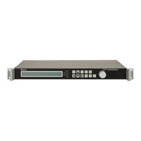
ASL INTERCOM VAR12 Operation Manual (308 pages)
DSP Audio Router
Brand:
ASL INTERCOM
| Category:
Network Router
| Size: 4 MB
Table of Contents
Table of Contents
3
1 Introduction
9
About this Document
9
VAR Router SW Version
9
2 VAR Router Operation
10
VAR Router Front Panel
10
Indicators
10
Controls
11
Access Code
12
LCD Display Timeouts
12
Restoration of Default Settings
12
Responding to Fault Indications
13
Records
13
Action Following a Fault
13
Navigating the Menus
14
Display Structure
14
Menu Selection Markers
14
Selecting Menu Item and Saving Changes
14
Changing an Option
15
Rotary Encoder
15
Conventions Used in this Manual
15
Menu Map of Functions
16
3 Typical Configuration Process
18
4 Accessing the VAR Router
20
Initialisation
20
Logging on
21
Logging off
21
Changing the System Access Code
22
5 VAR Router Configuration
23
VAR Router Operation Mode
23
Network Topology
23
Main Network Features
23
System Parameters
23
Setting the VAR Router to Stand-Alone Operation
25
Network Channel Configuration
25
MIC/Line Inputs 1, 3 and 4 Type Configuration
26
Setting the VAR Router to Network Operation
27
Network Channel Configuration
27
MIC/Line Input Configuration as Network Channel
28
Network Channel Surveillance Tone Detection
29
Network Channel Equalisation Configuration
30
Network Channel Fade up and down Time Configuration
31
Network Channel Pre-Announcement Chime Configuration
32
Network Channel Input Gain and the Line Sensitivity Configuration
33
Network Channel Relative Gain Configuration
34
Network Channel Name Configuration
35
Network Input Ambient Noise Sensor (ANS) Configuration
37
Network Input Fallback
39
Audio Control Unit Configuration
40
Network Priority Configuration
40
Var ID
41
VAR Router Name
41
System Date / Time
42
Temperature
43
Asynchronous Port
43
Emergency Sounder Operation
44
Remote Fault Output Configuration
44
Host Protocol Configuration
46
Routing Timeout Configuration
46
Fault Timeout Configuration
47
Make Route Message Format Configuration
47
Password Control Configuration
48
Configuration Data
50
Configuration Data View
50
Clearing Configuration Data and Restoring to Default Settings
50
VAR Router Software Versions
51
6 ASL Amplifier Mainframe Commissioning
52
Detecting Frames Using 'Learn' Mode
52
Viewing Configured Mainframes
54
Verbose View
54
Terse View
55
Mainframe Commissioning
56
Viewing a Mainframe Configuration
56
Editing/Viewing a Mainframe Description
57
Configuring a Mainframe Temperature Alarm
58
Commissioning an Amplifier Slot
59
Editing/Viewing an Amplifier Slot Description
59
Configuring an Amplifier's AC Surveillance Tone Frequency Range
60
Configuring an Amplifier's Internal Audio Path AC Surveillance
60
Configuring an Amplifier's AC Surveillance Thresholds
62
Configuring an Amplifier's AC Surveillance Interval
64
Configuring an Loudspeaker Line DC Surveillance
65
Configuring an Loudspeaker Line Earth Leakage Monitoring
67
Mainframe Learn Check
68
7 MIC/Line Input Configuration
70
MIC/Line Input Type Configuration
73
Parameters Common to All MIC/Line Input Types
75
Input Surveillance Tone Detection Configuration
75
Input Equalisation Configuration
77
Input Fade up and down Time Configuration
79
Input Pre-Announcement Chime Configuration
82
Input Gain and the Line Sensitivity Configuration
84
Input Relative Gain Configuration
86
Input Priority Configuration
88
Input Phantom Power Configuration
90
Input Emergency Class
91
Input Name Configuration
93
Input Ambient Noise Sensor (ANS) Configuration
94
Local Fallback Configuration
96
Paging Microphone and Zoned Fire Microphone Specifics
98
PTT Button Configuration
98
PTT Button Cough Timeout Configuration
100
Listen-In Configuration
102
Microphone Button Configuration
105
Configuring a Button as Unused
106
Configuring a Button for Microphone Routing (Zone Selection)
109
Configuring a Button for DVA Routing/Other Input Routing
112
Configuring the Route for a DVA Routing Button
115
Configuring a DVA Routing Button for Non-Latching Mode
118
Configuring a DVA Routing Button for Latching Mode
120
Configuring a DVA Routing Button for Play Once Mode
123
DVA Routing Button Busy Indication Configuration
125
DVA Routing Button DVA Play Mode Configuration
127
Clearing the Route Associated with a DVA Routing Button
129
Configuring a Button as an All-Call Button
130
Security Key-Switch Configuration
133
Single Button Microphone Specific Configuration
135
PTT Button Zone Selection Configuration
135
PTT Button Cough Timeout Configuration
137
8 DVA Input Configuration
139
DVA Input Gain Configuration
139
DVA Input Relative Gain Configuration
140
DVA Input Priority Configuration
141
DVA Input Emergency Class
143
DVA Input Name Configuration
145
DVA Input Ambient Noise Sensor (ANS) Configuration
146
9 Background Music Configuration
148
Music Input Configuration
149
Music Input Equalisation Configuration
149
Music Input Fade up and down Time Configuration
150
Music Input Gain Configuration
152
Music Input Relative Gain Configuration
153
Music Input Priority Configuration
154
Music Input Emergency Class
155
Music Input Name Configuration
155
Music Input Ambient Noise Sensor (ANS) Configuration
156
Contact Music Selector Configuration
158
10 Mute Input Configuration
160
Mute Input Emergency Class
160
Mute Input Priority Set-Up
161
11 Test Tone Input Configuration
163
Test Tone Type Configuration
164
Test Tone Input Gain Configuration
164
Test Tone Input Priority Set-Up
165
12 Output Configuration
167
Gain Configuration
167
Equalisation Configuration
168
Ambient Noise Sensor (ANS) Configuration
170
Enabling/Disabling the ANS and Setting the Attack Time
172
Configuring the ANS Range
173
Surveillance Tone Generation Configuration
175
Override Gain Configuration
177
Name Configuration
178
13 Induction Loop Configuration
180
Setting the VAR Router to Support Induction Loop
182
Induction Loop Output Gain Configuration
183
Induction Loop Output Surveillance Tone Generation Configuration
184
Induction Loop Output Override Gain Configuration
186
Induction Loop Output Name Configuration
187
Induction Loop Parameter Configuration
188
Configuring the Induction Loop Type
188
Equalisation Configuration
189
Audio Compression Configuration
190
14 Contact Configuration
193
Configuring a Contact as Unused
194
Configuring a Contact for Routing
196
Configuring the Zone Selection for a Routing Contact
199
Configuring a Routing Contact for Non-Latching Mode
201
Configuring a Routing Contact for Latching Mode
203
Configuring a Routing Contact for Play Once Mode
205
Routing Contact Busy Indication Configuration
207
Routing Contact DVA Play Mode Configuration
209
Clearing the Zone Selection Associated with a Routing Contact
211
Configuring a Contact as an External Alarm Input
212
Configuring a Contact as Remote Fault Accept
215
15 Permanent Route Configuration
217
16 ASL BMB01 Remote I/O Expander Configuration
219
Remote I/O Unit RS485 Bus Configuration
219
Remote I/O Unit Analogue Input Configuration
221
Configuring an Analogue Input as Unused
221
Configuring an Analogue Input as Programme Selector
223
Configuring an Analogue Input as Volume Control
227
Configuring an Analogue Input as Fault Input
231
Configuring an Analogue Input as Ambient Noise Sensor (ANS)
233
Remote I/O Unit Digital Input (Contact) Configuration
236
Configuring a Digital Input (Contact) as Unused
236
Configuring a Digital Input (Contact) for Routing
238
Configuring the Zone Selection for a Routing Digital Input (Contact)
241
Configuring a Routing Digital Input (Contact) for Non-Latching Mode
243
Configuring a Routing Digital Input (Contact) for Latching Mode
245
Configuring a Routing Digital Input (Contact) for Play Once Mode
247
Routing Digital Input (Contact) Busy Indication Configuration
249
Routing Digital Input (Contact) DVA Play Mode Configuration
251
Clearing the Zone Selection Associated with a Routing Digital Input (Contact)
253
Configuring a Digital Input (Contact) as an External Alarm Input
254
Remote I/O Unit Digital Output Configuration
256
17 Night Time Volume Control
259
Enabling/Disabling the Night Time Volume Control
259
Setting the Night Time Volume Control Active Time
259
Configuring the Maximum Output Level
260
Configuring the Affected Inputs
260
18 Testing
262
Lamp and Sounder Testing
262
Monitoring
263
Amplifier and Input Level Monitoring
263
ANS Monitoring
264
Routing Monitoring
265
Viewing the Contact Status
266
Viewing the VAR Router Base Unit Contact Status
266
Viewing the VAR Router Expand Unit Contact Status
266
Viewing a Remote I/O Unit Contact Status
267
Amplifier Changeover Testing
268
Mainframe Status
269
Mainframe Dip Switch Settings
269
Mainframe Battery Voltage
270
Battery Voltage Feeding Slots 1 and 2
270
Battery Voltage Feeding Slots 3 and 4
271
Mains Derived DC Supply Feeding Slots 1 and 2
271
Mains Derived DC Supply Feeding Slots 3 and 4
272
Auxiliary DC Supply Voltage
272
Mainframe Ambient Temperature
273
Amplifier Status
274
Amplifier Type and Revision Level
274
Amplifier Detailed Status
275
Amplifier Input Surveillance Tone Level
276
Amplifier Output Surveillance Tone Level
277
Amplifier DC Line Reading
278
Earth Leakage Reading
279
19 PC Configuration Tool
280
Connection
280
Starting a New Configuration
280
Loading the Configuration from the Unit
280
Loading the Configuration from a File
281
Saving the Configuration as Text File
281
Applying Changes to the Unit
281
20 Fault Monitoring
282
Current Fault Status
283
Fault Acceptance
283
Fault Clearance
283
Fault Log
284
System Fault Log
284
Mainframe Fault Log
284
Clearing the VAR Router Fault Log
285
Fault Codes and Suggested Actions
286
21 Maintenance
293
Training
293
Records
293
Maintenance Instructions
294
Routine Maintenance
294
Daily Attention
294
Monthly Attention
294
Quarterly Inspection and Test
294
Weekly Attention
294
Annual Inspection and Test
295
Replacement of the Real Time Clock Battery
295
Corrective Maintenance
296
Action by the User after any Fire (Whether Detected Automatically or Not)
296
Action Following a Fault
296
22 VAR Router Software Update
297
23 Manual Settings
298
Manual Restoration of Default Settings
298
Restoring Access Code
298
Restoring All Defaults
298
Default Settings
299
Fault Clear Access Level
301
24 Safety and Precautions
302
Environmental
302
Esd
302
Emc
302
Lithium Battery
302
Electrical Safety
302
Unpacking and Handling
302
Packing for Return for Repair
303
25 Reference Documents
304
26 Index
305
Service and Warranty
307
Advertisement
Advertisement
Related Products
ASL INTERCOM VAR4
ASL INTERCOM VAR20
ASL INTERCOM VAR8-ACU Series
ASL INTERCOM VAR8
ASL INTERCOM VAR8-E
ASL INTERCOM VIPET
ASL INTERCOM V2000
ASL INTERCOM VIPEDIA-12
ASL INTERCOM V400
ASL INTERCOM Categories
Intercom System
Power Supply
Amplifier
Accessories
Recording Equipment
More ASL INTERCOM Manuals
Login
Sign In
OR
Sign in with Facebook
Sign in with Google
Upload manual
Upload from disk
Upload from URL