Advertisement
Quick Links
Download this manual
See also:
Operating Manual
Advertisement

Related Manuals for ASL INTERCOM VAR4


Summary of Contents for ASL INTERCOM VAR4
- Page 1 VAR4 4x4 DSP Audio Router Installation Guide ASL Document Ref.: U-0450-1668.doc Issue: 02 complete, approved - Date: 02/12/09 Part Number: M0450_17...
-
Page 2: Table Of Contents
VAR4 – Installation Guide This equipment is designed and manufactured to conform to the following EC standards: EMC: EN55103-1/E1:1996, EN55103-2/E5:1996, EN50121-4:2006, ENV50204:1995 Safety: EN60065:2002 Failure to use the equipment in the manner described in the product literature will invalidate the warranty. -
Page 3: General Information
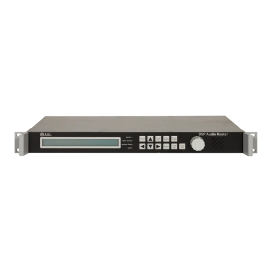
VAR4 – Installation Guide General Information Technical Specification Summary Supply Voltage Range ............................18 to 40 V DC Auxiliary DC Supply for External Equipment ..................18 − 36 V DC @ 100 mA Current Consumption ..............400 mA @ 24 V DC supply (backlight on and sounder on) 350 mA @ 24 V DC supply (backlight off and sounder off) Temperature (storage and operating) / Humidity Range .........−5°C to +50 °C / 0% to 93% non-condensing... - Page 4 VAR4 – Installation Guide Front Panel Indicators and Controls STATUS INDICATORS power processor comms fault ROTARY ENCODER LOUDSPEAKER LCD DISPLAY KEYS Issue: 02 complete, approved Page 4 of 20...
- Page 5 VAR4 – Installation Guide Indicators and Controls Description 2 x 40 backlit alphanumeric display. LCD Display Used to display the control menu, faults, and configuration data. power green Lit only if the unit is receiving DC power from both sources.
-
Page 6: Installation
VAR4 – Installation Guide Installation Equipment and Tool Requirements • The VAR4 Router. • Cabling as specified in “External Cabling Requirements” (page 6) to suit your system design. • A small flat-bladed screwdriver. • A pair of wire cutters/strippers. •... - Page 7 Failure to follow these instructions and guidelines may cause personal injury and/or damage to the equipment. Fit the VAR4 into a 19-inch standard equipment rack on supporting rails, and secure the unit in position using the fixing screws and washers provided; see Figure 1.
- Page 8 VAR4 – Installation Guide Ensure that the power supply from the central equipment rack is turned off. Connect the field wiring as required; see Figure 3. Please refer to Section “3 Connections” (page 9) for pinout details. Figure 3 Connecting the field wiring...
-
Page 9: Connections
VAR4 – Installation Guide Connections Issue: 02 complete, approved Page 9 of 20... - Page 10 VAR4 – Installation Guide Issue: 02 complete, approved Page 10 of 20...
- Page 11 VAR4 – Installation Guide PSU 1 and PSU 2: Dual DC Power Supply 2-way pluggable Wago cage clamp terminal (female) Signal Description +V supply (18 V to 40 V DC) 0 V supply PSU1 should come from an ASL Amplifier Mainframe AUX DC SUPPLY OUT terminations.
- Page 12 VAR4 – Installation Guide AUDIO-CAN: Audio CAN Port AUDIO MON- CAN_L Standard 9-way D connector (male) AUDIO Pin No Signal Description MON+ 1, 6, 8, 9 Not connected CAN_L Controller Area Network (Low) 0 V Reference AUDIO MON- Audio Monitor Bus –10 dBu nominal...
- Page 13 VAR4 – Installation Guide A-OUTPUTS and B-OUTPUTS: Audio Outputs 1 to 4 Standard 15-way D connector (male) Pin No Signal Description Audio A-OUTPUTS OUT-1A+ Balanced audio output 1 A (0 dBu nominal @ Z=660 Ω) OUT-2A OUT-4A OUT-1A- OUT-2A+ Balanced audio output 2 A...
- Page 14 VAR4 – Installation Guide CONTROL PORT 1: Control Port (Contacts 1 to 10 and other controls) ALL-CALL-1 (FIRE MIC-1 PTT) REMOTE REMOTE CONTACT-10 CONTACT-6 CONTACT-2 FAULT-1 FAULT-2 FAULT RELAY ALL-CALL-2 (FIRE MIC-2 PTT) CONTACT-8 CONTACT-4 CONTACT-7 CONTACT-3 SPEAK-NOW LED-1 CONTACT-9...
- Page 15 VAR4 – Installation Guide CONTROL PORT 2: Control Port (Contacts 11 to 22) CONTACT-22 CONTACT-20 CONTACT-18 CONTACT-16 CONTACT-14 CONTACT-12 CONTACT-21 CONTACT-19 CONTACT-17 CONTACT-15 CONTACT-13 CONTACT-11 Standard 25-way D connector (female) Signal Description Pin No CONTACT-11+ Opto-isolated Contact 11 (opto-anode) CONTACT-11-...
-
Page 16: Mechanical Dimensions
VAR4 – Installation Guide Mechanical Dimensions Figure 5 VAR4 mechanical dimensions 436 mm 44 mm = 1 U 483 mm THIRD ANGLE PROJECTION ASL recommend a rear clearance depth of at least 110 mm for cabling. A 19-inch standard rack with 600 mm depth provides the required room for installation including the rear cabling. -
Page 17: Safety And Precautions
VAR4 – Installation Guide Unpacking and Handling Safety and Precautions The equipment should be unpacked and inspected immediately on receipt. If damage has occurred please Environmental advise your carrier or supplier. Always ensure adequate ventilation is provided for the equipment by fitting 1U ventilation panels above and... - Page 18 VAR4 – Installation Guide Notes Issue: 02 complete, approved Page 18 of 20...
- Page 19 VAR4 – Installation Guide Notes Issue: 02 complete, approved Page 19 of 20...
-
Page 20: Application Solutions (Safety And Security) Limited
Service and Warranty Name and Address of Authorised Distributor: This product carries a full warranty. For full details of warranty and service agreements, please contact the Authorised Distributor who supplied the product to you. Exclusions The warranty does NOT cover: Customer misuse, including incorrect installation.
Need help?
Do you have a question about the VAR4 and is the answer not in the manual?
Questions and answers