Zte ZXR10 8900 Series Hardware Installation Manual
Zxr10 8900 series 10 gigabit routing switch
Hide thumbs
Also See for ZXR10 8900 Series:
- User manual (186 pages) ,
- Command manual (177 pages) ,
- Command reference manual (147 pages)
Table of Contents
Advertisement
ZXR10 8900 Series
10 Gigabit Routing Switch
Hardware Installation Manual
Version 2.8.02C
ZTE CORPORATION
ZTE Plaza, Keji Road South,
Hi-Tech Industrial Park,
Nanshan District, Shenzhen,
P. R. China
518057
Tel: (86) 755 26771900
Fax: (86) 755 26770801
URL: http://ensupport.zte.com.cn
E-mail: support@zte.com.cn
Advertisement
Table of Contents

Related Manuals for Zte ZXR10 8900 Series


Summary of Contents for Zte ZXR10 8900 Series
- Page 1 ZXR10 8900 Series 10 Gigabit Routing Switch Hardware Installation Manual Version 2.8.02C ZTE CORPORATION ZTE Plaza, Keji Road South, Hi-Tech Industrial Park, Nanshan District, Shenzhen, P. R. China 518057 Tel: (86) 755 26771900 Fax: (86) 755 26770801 URL: http://ensupport.zte.com.cn E-mail: support@zte.com.cn...
- Page 2 The contents of this document are protected by copyright laws and international treaties. Any reproduction or distribution of this document or any portion of this document, in any form by any means, without the prior written consent of ZTE CORPO- RATION is prohibited.
-
Page 3: Table Of Contents
Contents About This Manual..........i Safety Description ..........1 Safety Introduction ............1 Safety Description ............1 Equipment Installation ........3 Installation Content ............3 Equipment Component ............ 4 Equipment Installation Flow ..........6 Installation Preparation ........9 NOC Room Inspection ............. 9 Indoor Environment of NOC Room Inspection ....10 Power Supply Requirements Inspection ......13 Grounding Inspection .............13... - Page 4 Design of Fixed Base .........32 Positioning Fixed Base ........34 Installing Fixed Base .........36 Cabinet Installation............37 Cabinet Installation Requirements........37 Cabinet Installation Preparation ........37 Cabinet Installation Flow ..........38 Cabinet Installation Mode ...........39 Installing Cabinet by Adjustable Base ....39 Installing Cabinet on Floor Directly ......42 Installing Cabinet by Fixed Base......44 Connecting the Cabinets ..........49 Cabinet Accessories Remove and Installation.....51...
- Page 5 AC Power Supply Cable ..........84 Grounding Wire Installation ..........85 Grounding Wire Interconnection inside the Cabinet ..85 Grounding Wire Interconnection between Cabinets ..85 Plug-in Box Protection Grounding Wire Installation ..86 Installation Notice ............86 External Cable Installation ......87 External Cable Types............87 Control Console Cable Installation........87 Network Cable Installation ..........88 Fiber Installation ............89...
-
Page 7: About This Manual
About This Manual This manual provides procedures and guidelines that support the Purpose operation of ZXR10 8900 Series (V2.8.02.C) 10 Gigabit Routing Switch. This manual is intended for engineers and technicians who perform Intended Audience operation activities on ZXR10 8900 Series (V2.8.02.C) 10 Gigabit Routing Switch. - Page 8 ZXR10 8900 Series Hardware Installation Manual � ZXR10 8900 Series (V2.8.02.C) 10 Gigabit Routing Switch User Manual (Ethernet Switching Volume) � ZXR10 8900 Series (V2.8.02.C) 10 Gigabit Routing Switch User Manual (IPv4 Routing Volume) � ZXR10 8900 Series (V2.8.02.C) 10 Gigabit Routing Switch User Manual (MPLS Volume) �...
-
Page 9: Safety Description
Safety precautions introduced in this manual are supplementary to the local safety codes. � ZTE bears no responsibility in case of universal safety oper- ation requirements violation and safety standards violation in designing, manufacturing and equipment usage. Safety Description... - Page 10 ZXR10 8900 Series Hardware Installation Manual This page is intentionally blank. Confidential and Proprietary Information of ZTE CORPORATION...
-
Page 11: Equipment Installation
Equipment Component ............4 Equipment Installation Flow ..........6 Installation Content Installation diagram of ZXR10 8900 is shown in Figure 1 ZXR10 8900 I IGURE NSTALLATION IAGRAM Thick real line implies the parts required installing. Confidential and Proprietary Information of ZTE CORPORATION... -
Page 12: Equipment Component
ZXR10 8900 Series Hardware Installation Manual Equipment Component ZXR10 8900 is composed of the following parts: � 19”standard cabinet (optional) � ZXR10 8900 case � Card � Power supply module � Fan modules Master device can be installed in 19” standard cabinet, and it also can be installed on working table. -
Page 13: Figure 3 Side Elevation Of Zxr10 8908
ZXR10 8908 IGURE LEVATION OF The side elevation of ZXR10 8905 with six slots is shown in Figure ZXR10 8905 IGURE LEVATION OF The front panel view of ZXR10 8902 is shown in . Confidential and Proprietary Information of ZTE CORPORATION... -
Page 14: Equipment Installation Flow
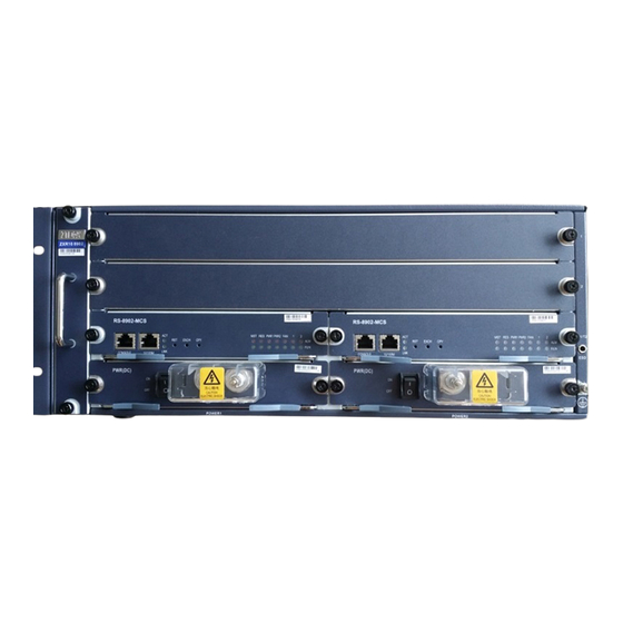
ZXR10 8900 Series Hardware Installation Manual ZXR10 8902 IGURE RONT ANEL IEW OF Basic parameters of ZXR10 8900 are described in Table ABLE ASIC ARAMETERS Items ZXR10 8912 ZXR10 8908 ZXR10 8905 ZXR10 8902 Size (mm) 754.8×442×450 577× 442×450 443.7×442×450 174×... -
Page 15: Figure 6 Equipment Installation Flow
Chapter 2 Equipment Installation IGURE QUIPMENT NSTALLATION Confidential and Proprietary Information of ZTE CORPORATION... - Page 16 ZXR10 8900 Series Hardware Installation Manual This page is intentionally blank. Confidential and Proprietary Information of ZTE CORPORATION...
-
Page 17: Installation Preparation
0.8m. Moreover, a pass not less than 1.2m must be reserved for the NOC room, as shown in Figure 7 NOC R IGURE AYOUT � Load on NOC room floor Confidential and Proprietary Information of ZTE CORPORATION... -
Page 18: Indoor Environment Of Noc Room Inspection
ZXR10 8900 Series Hardware Installation Manual This must not be less than 450kg/ m � Net height Net height of the NOC room must be more than 3.20m. If the net height of the NOC room is less than 3.2m, special instruc- tion must be given in project design document, explaining the cable routing. - Page 19 Walls and ceiling of equipment room must be painted or pasted with wall paper. This is better to use lusterless paint. � Temperature and humidity requirements Temperature and humidity requirements are shown in Table Confidential and Proprietary Information of ZTE CORPORATION...
-
Page 20: Table 4 Temperature And Humidity Requirements
ZXR10 8900 Series Hardware Installation Manual ABLE EMPERATURE AND UMIDITY EQUIREMENTS Temperature Relative Humidity Items Long-term Long-term Short-term Short-term working working working working condition conditions condition conditions Range 15°C -5°C 40%~65% 20%~90% ~30°C ~45°C Note: When equipment is in normal running environment, tem- �... -
Page 21: Power Supply Requirements Inspection
Inspection Power supply requirements inspection includes DC and AC power supply requirements inspection. Nominal voltage of power supply provided for ZXR10 8900 series DC Power Supply switch by equipment room is -48V and the allowed variation range is -57V~ -40V. -
Page 22: Required Tools
ZXR10 8900 Series Hardware Installation Manual � Power supply must be ready and capacity is sufficient for this project. � Transmission equipment related to this project must have been prepared. � Terminal device must be equipped with a dedicated terminal console. -
Page 23: Technical Document Preparation
Preparation Installation engineering personnel must refer to following delivery- attached documents: � ZXR10 8900 Series 10 Gigabit Routing Switch Hardware Man- � ZXR10 8900 Series 10 Gigabit Routing Switch Hardware Instal- lation Manual Confidential and Proprietary Information of ZTE CORPORATION... - Page 24 ZXR10 8900 Series Hardware Installation Manual This page is intentionally blank. Confidential and Proprietary Information of ZTE CORPORATION...
-
Page 25: 19" Standard Cabinet Installation
The layout of cabinet must be convenient for installation, main- tenance and system extension. � The arrangement of cabinet is decided by system configuration. It must be designed with involvement of supplier’s technical personnel and confirmed by the supplier. Confidential and Proprietary Information of ZTE CORPORATION... -
Page 26: Cabinet Base Installation Preparation
ZXR10 8900 Series Hardware Installation Manual Cabinet Base Installation Preparation Prepare necessary instruments and project design material and installation guide material before cabinet base installation. � Engineering Design and Installation Drawing � Tools Steel tapeline � For measure cabinet position suit cabinet installation re- quirement or not, measure adjustable base positioning hole size, diameter and other measurement. -
Page 27: Adjustable Base Installation Mode
IGURE DJUSTABLE NSTALLATION Adjustable Base Selection ZTE provides adjustable bases with three ranges for installation and fixation of cabinets on antistatic floors in the equipment rooms. The adjustable bases are divided into three types A, B and C ac- cording to the adjustable range L. Two bases are required for fixing each cabinet. -
Page 28: Figure 9 Adjustable Base: Model A
ZXR10 8900 Series Hardware Installation Manual IGURE DJUSTABLE ODEL � Model B: 210mm ~310mm, as shown in Figure 10 A IGURE DJUSTABLE ODEL � Model C: 310mm ~510mm, as shown in Figure 11 A IGURE DJUSTABLE ODEL Note: Above adjustment range means the height between cabinet base and floor after cabinet installation. -
Page 29: Figure 12 Adjustable Base Installation Diagram
Adjustable base structure diagram (Model B) is shown in Figure 13 A IGURE DJUSTABLE TRUCTURE IAGRAM ODEL Fixing frame Flexible frame High locked bolt M12 × 25 Sleeve M12 Spring washer Flat washer Expand Bolt M12×80 Confidential and Proprietary Information of ZTE CORPORATION... -
Page 30: Positioning Adjustable Base
ZXR10 8900 Series Hardware Installation Manual Positioning Adjustable Base Make sure of base installation position as per standard dimensions and cabinet dimensions given in layout drawings. Measure the marking points with the tape and mark out two straight lines with a distance of 610mm that are parallel with benchmark. -
Page 31: Figure 15 Positions Of Dual Cabinet Installation
Cabinet 19D10H20 Direct Server Cabinet L1 is the distance from side gate to the wall of cabinet room, L1≥900mm. L2 is the distance from front gate and front gate to cabinet room, L2≥1500mm. Confidential and Proprietary Information of ZTE CORPORATION... -
Page 32: Installing Adjustable Base
ZXR10 8900 Series Hardware Installation Manual Note: To avoid mistakes, measure over and over after all holes line are marked, and make sure every size is correct. 2. Drilling Drill φ14 at the expansion bolt hole marked on the floor with a depth of 90 mm. -
Page 33: Figure 16 Adjustable Base Height Diagram
C third blank C fourth blank base blank installation hole Antistatic 410≤H435 435≤H460 460≤H485 485≤H≤510 floor height Adjustable C fifth blank C sixth blank C seventh C eighth base blank blank installation hole Confidential and Proprietary Information of ZTE CORPORATION... -
Page 34: Figure 17 Fixation Of Adjustable Base
ZXR10 8900 Series Hardware Installation Manual After adjustment tighten the bolt to 45Nm with a torque wrench, tighten flexible frame with activity frame. The side bolt must be tightened first, then tighten front bolt, to ensure that activity frame and fixing frame are connected tightly. -
Page 35: Installation Of Base Directly On Floor
Installation of Base Directly on Floor Installation Flow of Base Directly on Floor This installation mode is suitable for cement ground, adopting pressure plate to fix footings with ground. Installation flow is shown in Figure Confidential and Proprietary Information of ZTE CORPORATION... -
Page 36: Installing Base On Floor Directly
ZXR10 8900 Series Hardware Installation Manual 20 I IGURE NSTALLATION LOW OF IRECTLY ON LOOR Installing Base on Floor Directly Make sure of base installation position as per standard dimensions and cabinet dimensions given in layout drawings. To install base on floor directly, perform the following steps. -
Page 37: Figure 21 Position Single Cabinet Installation
OSITION ABINET NSTALLATION Equipment room wall Cabinet outline M12 expand bolt installation Front door of Cabinet hole For the value of L1, l2 and A, B and C, D, please refer to Table Confidential and Proprietary Information of ZTE CORPORATION... -
Page 38: Table 7 Installing The Base Directly Marking Size
ZXR10 8900 Series Hardware Installation Manual ABLE NSTALLING IRECTLY ARKING Cabinet Name 19D6H20 L2+52 L1+40 Cabinet 19D8H20 L2+52 L1+40 Cabinet 19D8H20EMC Cabinet 19D8H20EMC Standard cabinet 19D10H20 L2+152 L1+40 Cabinet 19D10H20 Alternate server Cabinet 19D10H20 Direct server Cabinet L1 is the distance from side gate and to the wall of cabinet room, L1≥900mm. -
Page 39: Installation Of Fixed Base Mode
This installation is suitable for user-designed base or a base has been installed on the NOC room. Take 19D8H20 cabinet as example, fixed base with design, position and installation. Installation flow of fixed base is shown in Figure Confidential and Proprietary Information of ZTE CORPORATION... -
Page 40: Design Of Fixed Base
NSTALLATION LOW OF IXED Design of Fixed Base Customer designs the base by themselves according to ZTE cabi- net base installation structure and size. 19D8H20 of single cabinet drill size is shown in Figure Confidential and Proprietary Information of ZTE CORPORATION... -
Page 41: Figure 25 19D8H20 Single Cabinet Drill Installation Diagram
Installation base is made up from welded angle steels, as shown Figure Oval installation holes in figure have sizes of 18mm×30mm for fine location adjustment during installation. Height H depends on height of antistatic floor. Confidential and Proprietary Information of ZTE CORPORATION... -
Page 42: Positioning Fixed Base
ZXR10 8900 Series Hardware Installation Manual 27 19D8H20 S IGURE INGLE ABINET IXED IAGRAM This design is only for reference. Customer can design it according to the specific requirements. Positioning Fixed Base Define for cabinet installation positions as per standard dimensions given in the layout drawings. -
Page 43: Figure 28 19D8H20 Single Cabinet Installation Diagram
Drill φ14 at the expansion bolt hole marked on the floor with a depth of 90 mm. Make sure drill is perpendicular to floor when drilling with per- cussion drill (or hammer). Hold handle tightly and vertically to Confidential and Proprietary Information of ZTE CORPORATION... -
Page 44: Installing Fixed Base
ZXR10 8900 Series Hardware Installation Manual avoid sway, otherwise the floor will be damaged and hole will be enlarged and inclined. Use a vacuum cleaner to remove the dust after drilling. When floor is too slippery to position drill bit, cut a dent at the perforation position with punch first to help locating drill bit. -
Page 45: Cabinet Installation
Chapter 4 19” Standard Cabinet Installation If floor is not smooth, use shims provided by ZTE, the shims are of 1mm and 2mm thick. After installing the cabinet, inspect the NOC room environment and cabinet. Clear the installation garbage and sundries from NOC room. -
Page 46: Cabinet Installation Flow
ZXR10 8900 Series Hardware Installation Manual Plumb � It measures the verticality of cabinet. Wrench � It measures the height of footing. � Multimeter It measures the resistance between grounding point and ex- pansion bolt on floor. Cabinet Installation Flow... -
Page 47: Cabinet Installation Mode
To install cabinet, perform the following steps. 1. Cabinet Height Regulation There are four footings and truckles on the cabinet base. Loosen the four bolts that fasten the truckles. Remove four truckles, as shown in Figure Confidential and Proprietary Information of ZTE CORPORATION... -
Page 48: Figure 31 Remove Truckles
ZXR10 8900 Series Hardware Installation Manual 31 R IGURE EMOVE RUCKLES Cabinet Truckle Footing Bolt Loosen the locknuts that fasten the cabinet footings. Place the cabinet on the adjustable base manually or by lifting machine. Make sure that the right, left, front and back plane of cabinet are parallel with the NOC room walls. -
Page 49: Figure 33 Fix Cabinet
4. Insulation Test Modify the multimeter to resistance grade. Use the two mea- suring heads to touch the cabinet earthing point and expansion bolt. Measure their resistance. Continue with the next step if Confidential and Proprietary Information of ZTE CORPORATION... -
Page 50: Installing Cabinet On Floor Directly
ZXR10 8900 Series Hardware Installation Manual the circuit is an open circuit. If the result shows that it is not an open circuit, then the cabinet is not insulated with earth. Examine the insulated tube. Repeat the last step and insula- tion test. -
Page 51: Figure 36 Cabinet Base Is Installed On Floor Directly
If the result shows that it is not an open circuit, then the cabinet is not insulated with earth. Ex- amine the insulated tube. Repeat the last step and insulation test. Confidential and Proprietary Information of ZTE CORPORATION... -
Page 52: Installing Cabinet By Fixed Base
ZXR10 8900 Series Hardware Installation Manual Note: Insulation test has to be implemented immediately after each cabinet footing is fixed. Result: Cabinet has been installed on floor directly. Installing Cabinet by Fixed Base When cabinet bottom is installed by a fixed base, the cabinet can be fixed by two methods. -
Page 53: Figure 38 Footing Structure
At last fix the cabinet with flat washer, spring washer and blot. The fastening torque has to reach 45Nm. The pressure plate is attached with an insulated rubber pad. Pressure plate is shown Figure Confidential and Proprietary Information of ZTE CORPORATION... -
Page 54: Figure 39 Fix Cabinet By Pressure Plate
ZXR10 8900 Series Hardware Installation Manual 39 F IGURE ABINET BY RESSURE LATE Flat Washer Spring Washer Insulated Tube Pressure Plate Bolt M12×80 Footing Nut M12 Base 4. Insulation Test Modify the multimeter to resistance grade. Use the two mea- suring heads to touch the cabinet earthing point and expansion bolt. -
Page 55: Figure 40 Remove Truckles
As shown in Figure 41, place flat washer, spring washer on bolt, and fasten the bolt M16×100 in the direction of arrowhead. As a result, the cabinet is installed on the base. Confidential and Proprietary Information of ZTE CORPORATION... -
Page 56: Figure 41 Fix The Cabinet By Bolt
ZXR10 8900 Series Hardware Installation Manual 41 F IGURE IX THE ABINET BY Cabinet Spring Washer Base Screw M16×100 Flat Washer 3. Insulation Test Modify the multimeter to resistance grade. Use the two mea- suring heads to touch the cabinet earthing point and expansion bolt. -
Page 57: Connecting The Cabinets
90 degrees. Connect the angle supports back to back. The installation order is shown in Figure Figure 43 Figure 42 R IGURE EMOVE CREW OF NGLE UPPORT Fasten screws Angle support 43 R IGURE EMOVE THE NGLE UPPORT Confidential and Proprietary Information of ZTE CORPORATION... -
Page 58: Figure 44 Reinstallation The Angle Support
ZXR10 8900 Series Hardware Installation Manual 44 R IGURE EINSTALLATION THE NGLE UPPORT 4. Between two near cabinets, use six screws M8×12, flat washer, spring washer and M8 nut to connect angle support. The in- stallation of two near cabinets is shown in... -
Page 59: Cabinet Accessories Remove And Installation
1. Place the door to hinge on cabinet and keep the door and the pin hole on the same line. 2. Insert the pin and fasten the lock screw. 3. Connect the earthing cable. Door installation is shown in Figure Confidential and Proprietary Information of ZTE CORPORATION... -
Page 60: Installation And Clean Of Dustproof Mesh
ZXR10 8900 Series Hardware Installation Manual 46 D IGURE NSTALLATION IAGRAM Upper pin pivot Lower pin pivot Upper captive screw Lower captive screw Result: Front and back doors have been installed. Installation and Clean of Dustproof Mesh Dustproof meshes are provided for the cabinet front/back doors and for the cabinet bottom. -
Page 61: Installing And Cleaning Dustproof Plug-In Box
1. Remove screws of dustproof plug-in box. Outstretch dustproof plug-in box maintaining the balance by two hands, so that dust from dustproof meshes do not fall into the cabinet, as shown Figure Confidential and Proprietary Information of ZTE CORPORATION... -
Page 62: Installing And Cleaning Dustproof Mesh
ZXR10 8900 Series Hardware Installation Manual 48 O IGURE UTSTRUCTURE USTPROOF IAGRAM Dustproof plug-in box Screw 2. Open dustproof plug-in box and take out the dustproof meshes. 3. Clean the dustproof mesh by warm water (≤40℃), and dry it. 4. Push the dustproof mesh into the dustproof plug-in box. -
Page 63: Installing Panel Wood
Keep the connection hole of front and back panel woods and the connection hole of cabinet installation frame on the same line. Use screw to fix front and back panel woods, as shown in Figure Confidential and Proprietary Information of ZTE CORPORATION... -
Page 64: Figure 51 Fix Front And Back Panel Wood
ZXR10 8900 Series Hardware Installation Manual 51 F IGURE RONT AND ANEL Screw Back panel wood Front panel wood For dual cabinets, install back and front panel woods of the first cabinet, and then install back and front panel woods of others in turn. -
Page 65: Installing Top Panel And Top Inside Panel
Installing Top Panel and Top inside Panel To install top panel and top inside panel, perform the following steps. 1. Install Top Panel Install top panel and top inside panel according to customer requirement. Confidential and Proprietary Information of ZTE CORPORATION... -
Page 66: Figure 55 Top Panel Installation Diagram
ZXR10 8900 Series Hardware Installation Manual Front panel and back panel are necessary for one cabinet. Use M5×12 screws to connect the top panel with top of cabinet, as shown in Figure 55 T IGURE ANEL NSTALLATION IAGRAM Screw M5×12... -
Page 67: Figure 56 Top Inside Panel Installation Diagram
Top side panel Top panel Screw M5×12 Cabinet Angle support For dual cabinets, only top panel and top side panel are re- quired to install. Figure 57 shows the cabinet appearance after installation is finished. Confidential and Proprietary Information of ZTE CORPORATION... -
Page 68: Installing Power Supply Cable And Grounding Cable
ZXR10 8900 Series Hardware Installation Manual 57 I IGURE NSTALLATION OF ANEL AND NSIDE ANEL ABINET Result: Top panel and top inside panel have been installed. Installing Power Supply Cable and Grounding Cable DC distribution cabinet provides power supply of -48V for ZXR10 8900 cabinet. - Page 69 WITH CONNECTOR MODULE DC distribution cabinet Cover Screw ZXR10 8900 cabinet NOC room protective grounding Connector module Terminal The connection between ZXR10 8900 cabinet and DC distribution cabinet with filter is shown in Figure Confidential and Proprietary Information of ZTE CORPORATION...
- Page 70 ZXR10 8900 Series Hardware Installation Manual 59 DC D ZXR10 8900 IGURE ISTRIBUTION ABINET ONNECTING WITH WITH FILTER NOC room protective grounding Cover ZXR10 8900 cabinet DC distribution cabinet Terminal Screw Filter When the cables are required connecting, loosen the bolts first, remove the cover board and install the cables.
- Page 71 4. PE grounding bar of DC distribution cabinet is connected with protective grounding bar in NOC room through yellow green plastic-insulated copper conductor which wire diameter is the same with power bus line. Result: Power supply and grounding cable have been installed. Confidential and Proprietary Information of ZTE CORPORATION...
- Page 72 ZXR10 8900 Series Hardware Installation Manual This page is intentionally blank. Confidential and Proprietary Information of ZTE CORPORATION...
-
Page 73: Master Device Installation
3. Put up the end of the marked ruler on support rails of the cab- inet. 4. Install flexible floating nut on the front corner rail of the cabinet with installation spring as per the marked positions, as shown Figure Confidential and Proprietary Information of ZTE CORPORATION... -
Page 74: Figure 60 Floating Nut Installation
ZXR10 8900 Series Hardware Installation Manual 60 F IGURE LOATING NSTALLATION Corner rail Floating nut Installation spring 5. Two operators stand at right and left sides of the cabinet. The one on left side support the middle bottom of the plug-in box with his left hand, and hold the upper part of the plug-in box with his right hand. -
Page 75: Plugging And Unplugging Card
IGURE NSTALLATION OF UBRACK Result: Plug-in box has been installed Plugging and Unplugging Card To plug a card, perform the following steps. Plug a Card 1. The card structure is shown in Figure Confidential and Proprietary Information of ZTE CORPORATION... -
Page 76: Figure 62 Card Structure
ZXR10 8900 Series Hardware Installation Manual 62 C IGURE TRUCTURE Card Extractor Captive Screw Align the two sides of the card bottom steel with the guide rail slot of the plug-in box and push the card into the box, as shown... -
Page 77: Figure 63 Plugging Card Step 2
The extractor is nearly parallel to the card front. The card is plugged in place. 4. Secure the captive screws on both sides of the card using a screwdriver as shown in Figure Confidential and Proprietary Information of ZTE CORPORATION... -
Page 78: Installation Of Power Supply Module
ZXR10 8900 Series Hardware Installation Manual 65 P IGURE LUGGING Plug-in Box Captive Screw Card Result: The card has been plugged. To unplug a card, perform the following steps. Unplug a Card 1. Loosen the captive screw on both sides of the card with a screwdriver. -
Page 79: Figure 66 Plugging Power Module Step 1 (Zxr10 8908)
Secure the socket con- nector connection between the module and the back-plate, as shown in Figure Confidential and Proprietary Information of ZTE CORPORATION... -
Page 80: Figure 67 Plugging Power Module Step 2 (Zxr10 8908)
ZXR10 8900 Series Hardware Installation Manual 67 P 2 (ZXR10 8908) IGURE LUGGING OWER ODULE Plug-in box Power module 3. Hold the two sides or bottom of the power module guard with hands and pull the guard upward to remove it. Screw down the... -
Page 81: Figure 69 Fake Power Supply Module
Plug the fake power supply module into its corresponding module slot and remove the power guard, as shown in Figure 70. Fasten captive screws and fixed screw (M3 × 8). Confidential and Proprietary Information of ZTE CORPORATION... -
Page 82: Installing Power Supply Module Of Zxr10 8902
ZXR10 8900 Series Hardware Installation Manual 70 I IGURE NSTALL AND EMOVE OWER UPPLY ODULE Fake power supply module Screw Captive Screw � Remove fake power supply module Unplug card to leave enough space for using screwdriver be- fore fake power supply module is removed. Remove the power module guard, loose captive screw and fixed screw ((M3 ×... -
Page 83: Figure 71 Plugging Power Module Of Zxr10 8902 Step 1
Secure the socket connector connection between the module and the back-plate, as shown in Figure 72 P ZXR10 8902 S IGURE LUGGING OWER ODULE OF Plug-in Box Power Module Captive Screw Confidential and Proprietary Information of ZTE CORPORATION... -
Page 84: Installation Of Fan Plug-In Box
ZXR10 8900 Series Hardware Installation Manual Result: Power module of ZXR10 8902 has been plugged. To unplug power module of ZXR10 8902, perform the following Unplug Power Supply Module steps. 1. Loosen the captive screw on the bottom side of the module. -
Page 85: Installing Fan Plug-In Box Of Zxr10 8902
To plug fan plug-in box of ZXR10 8902, perform the following Plug Fan Plug-in steps. 1. Align the fan plug-in box with its slot, as shown in Figure Plug the box along the upper and lower guide rails. Confidential and Proprietary Information of ZTE CORPORATION... -
Page 86: Figure 75 Plugging Fan Plug-In Box Of Zxr10 8902 Step 1
ZXR10 8900 Series Hardware Installation Manual 75 P ZXR10 8902 S IGURE LUGGING OX OF Plug-in box Captive Screw on the Fan Fan Plug-in Box Plug-in Box Handle 2. When the connector on fan plug-in box touches the connector on the back-plate, as shown in... -
Page 87: Installation Of Cabling Rack
Keep waist-round holes of vertical supporter and that of plug-in box on the same line, fix the vertical supporter in cabinet with three crown screws, fasten the crown screws, as shown in Figure Confidential and Proprietary Information of ZTE CORPORATION... -
Page 88: Figure 77 Install Vertical Supporter In Cabinet
ZXR10 8900 Series Hardware Installation Manual 77 I IGURE NSTALL ERTICAL UPPORTER IN ABINET Crown screw Plug-in box Vertical supporter � Install vertical supporter in working table Make sure that plug-in box has been installed in working table already. Keep waist-round holes of vertical supporter and that... -
Page 89: Installing Horizontal Cable Plate
ZXR10 8912/8908/8905 use the same method to install horizontal cable plate. Here, take ZXR10 8908 for an example to introduce how to install horizontal cable plate, as shown in Figure Confidential and Proprietary Information of ZTE CORPORATION... -
Page 90: Figure 79 Horizontal Cable Plate Installation
ZXR10 8900 Series Hardware Installation Manual 79 H IGURE ORIZONTAL ABLE LATE NSTALLATION Horizontal cable plate Plug-in box Vertical supporter To install horizontal cable plate, perform the following steps. 1. Remove the captive screw from the left side of card which re- quires horizontal cable plate. -
Page 91: Power Supply Cables Installation
All the DC working ground wires have been connected to the cabinet shells inside the GND. The cabinet ground is the secondary protective ground for the equipment. It can discharge the remaining charges in the primary protective unit when it is Confidential and Proprietary Information of ZTE CORPORATION... -
Page 92: Ac Power Supply Cable
ZXR10 8900 Series Hardware Installation Manual connected to the earth. DC distribution system grounding is shown Figure 80 DC D IGURE ISTRIBUTION YSTEM ROUNDING Connect the –48 V (blue) and GND (black) to the customer-pro- vided –48 V power suppler device using 16mm conducting wires. -
Page 93: Grounding Wire Installation
When a joint ground is used, make sure the electric potentials of all the cabinet grounds are equal. Interconnect the cabinet shells using knitted strips or conductive copper wires. The cross sectional area of the interconnecting wire is 10 mm Confidential and Proprietary Information of ZTE CORPORATION... -
Page 94: Plug-In Box Protection Grounding Wire Installation
ZXR10 8900 Series Hardware Installation Manual A protective grounding wire is led from each cabinet to the joint copper ground bar, and connected to the copper ground bar in the equipment room through the grounding bus of the joint copper ground bar. -
Page 95: External Cable Installation
Microsoft Windows operating system. Control console cable is a category-5 twisted pair cable with two DB9 serial interfaces, as shown in Figure Confidential and Proprietary Information of ZTE CORPORATION... -
Page 96: Network Cable Installation
ZXR10 8900 Series Hardware Installation Manual 82 C IGURE ONTROL ONSOLE ABLE The specific connection relationship is shown in Table 10 C ABLE ONNECTIONS OF ONTROL ONSOLE ABLE End A (DB9 hole) Cable Chromatogram End B (DB9 hole) Blue Orange... -
Page 97: Fiber Installation
White and blue White and brown Brown Fiber Installation Optical fibers are used to connect optical interfaces. There are two types of fibers: single mode and multi-mode. They can be used as required. Confidential and Proprietary Information of ZTE CORPORATION... -
Page 98: Label Types
ZXR10 8900 Series Hardware Installation Manual Since fibers are slight and easy to be damaged in packing and shipping, they should be cabled and bound on the office site. Each optical interface should be connected with two fibers, one for data sending and the other for data receiving. -
Page 99: Figure 85 Roll-Up Self-Mulching Laser Print Type Ii Labels
The roll-up self-mulching laser print type II label is used when the cable connector size is smaller or use of the transverse English la- Confidential and Proprietary Information of ZTE CORPORATION... -
Page 100: Figure 86 Schematic Diagram Of A Power Cable Label
This is pasted on cable through the self-contained cellulose tape. � Power Cable Label Labels Pasted on Cables A flag-like label worked out by ZTE can be used as an engi- neering marker for power cables, as shown in Figure 86 S IGURE CHEMATIC... -
Page 101: Figure 88 Structure Of Optical Fiber
ZXR10 8900 side. � Coaxial Cable Label The structure of a coaxial cable label is shown in Figure Confidential and Proprietary Information of ZTE CORPORATION... -
Page 102: Figure 90 Structure Of Coaxial Cable Label
ZXR10 8900 Series Hardware Installation Manual 90 S IGURE TRUCTURE OF OAXIAL ABLE ABEL The meanings of a coaxial cable label are shown in Figure 91 M IGURE EANING OF OAXIAL ABLE ABEL Both sides of the coaxial cable label are marked with L and R. -
Page 103: Hardware Installation Inspection
The panels must be installed cor- rectly without any obvious gap. The indicator RUN will be on after the device getting electricity, and the indicator ALM will be on when the device alarms. Confidential and Proprietary Information of ZTE CORPORATION... -
Page 104: Power Supply Cable Inspection
ZXR10 8900 Series Hardware Installation Manual Power Supply Cable Inspection Power cable inspection includes the following parts: � Power cable check The connection of all power cables must be reliable and the polarity must be correct. � Grounding cable Confirm whether the -48VGND, GND and PE are correctly and reliably connected. -
Page 105: Figures
Figure 29 Installation of Base ..........36 Figure 30 Cabinet Installation Flow Diagram......39 Figure 31 Remove Truckles ..........40 Figure 32 Footing Structure ..........40 Figure 33 Fix Cabinet ............41 Figure 34 Pressure Pad and Insulated Rubber Pad ....41 Confidential and Proprietary Information of ZTE CORPORATION... - Page 106 ZXR10 8900 Series Hardware Installation Manual Figure 35 The clearance between Panel Wood and Floor ..42 Figure 36 Cabinet Base is Installed on Floor Directly....43 Figure 37 Remove Truckles ..........44 Figure 38 Footing Structure ..........45 Figure 39 Fix Cabinet by Pressure Plate ........46 Figure 40 Remove Truckles ..........47...
- Page 107 Figure 88 Structure of Optical Fiber........93 Figure 89 Meaning of Optical Fiber ........93 Figure 90 Structure of Coaxial Cable Label ......94 Figure 91 Meaning of Coaxial Cable Label ......94 Figure 92 Horizontal Model-I Label In English ......94 Confidential and Proprietary Information of ZTE CORPORATION...
- Page 108 ZXR10 8900 Series Hardware Installation Manual This page is intentionally blank. Confidential and Proprietary Information of ZTE CORPORATION...
-
Page 109: Tables
Table 9 Power Cable and Grounding Wires......83 Table 10 Connections of Control Console Cable ......88 Table 11 Straight-Through Network Cable RJ45 Connections..89 Table 12 Crossover Network Cable RJ45J Connections.....89 Table 13 Fiber Terminal Forms ..........90 Confidential and Proprietary Information of ZTE CORPORATION...
Need help?
Do you have a question about the ZXR10 8900 Series and is the answer not in the manual?
Questions and answers