Table of Contents
Advertisement
Quick Links
Advertisement
Table of Contents

Related Manuals for GRAPHTEC GL450


Summary of Contents for GRAPHTEC GL450
- Page 1 GL450 USER’S MANUAL MANUAL NO. GL450-UM-151...
-
Page 2: Introduction
User's Manual. Moreover, use of the GL450 by incorrect procedures may result in damage to the GL450 or may invalidate its safeguards. Please confirm all of its notes regarding use and other related information to ensure correct use. - Page 3 (7) Insofar as possible, position the GL450 input signal cables away from any other cables which are likely to be affected by electromagnetic interference. (8) For stabilized measurement, allow the GL450 to warm up for at least 30 minutes after turning it on.
-
Page 4: To Ensure Safe And Correct Use
Conventions Used in This Manual To promote safe and accurate use of the GL450 as well as to prevent human injury and property damage, safety precautions provided in this manual are ranked into the five categories described below. Be sure you understand the difference between each of the categories. -
Page 5: Safety Precautions
50 V (DC or rms). If the GL450 generates smoke, is too hot, emits a strange odor , or otherwise functions abnormally, turn off its power and unplug its power cord from the electrical socket. - Page 6 Safety Precautions Safety Precautions WARNING Avoid using the GL450 in places where it may be exposed to water such as bathrooms, locations exposed to wind and rain, and so on. Avoid water Watch out for electrical shock Prevent dust or metallic matter from adhering to the power supply connector.
- Page 7 Safety Precautions Safety Precautions CAUTION Do not use or store the GL450 in a location exposed to direct sunlight or the direct draft of an air conditioner or heater. • Such location may impair the GL450's performance. Storage/Use prohibited Do not place coffee cups or other receptacles containing fluid on the GL450.
- Page 8 • Such action may cause the GL450 to break down. No lubrication Never clean the GL450 using a volatile solvent (such as thinner or benzine). • Such action may impair the GL450's performance. • Clean off any soiled areas using a soft dry cloth.
-
Page 9: Table Of Contents
2 Checks and Preparation Checking the Outer Casing ....................... 2-2 Checking the Accessories ......................2-2 GL450 Part Names and Functions ................... 2-3 Monitor Part Names and Functions ..................2-4 Control Panel Key Part Names and Functions ............... 2-5 Connecting to a PC ........................2-6 Connection Using a LAN Cable .................... - Page 10 Contents Attaching the Input Cable ......................2-14 2.12 Precautions to Observe When Performing Measurement ........... 2-15 2.13 Noise Countermeasures ......................2-16 2.14 Logic/Alarm Functions ......................2-17 2.15 Trigger/Pulse Functions ......................2-18 2.16 Connecting the Humidity Sensor ................... 2-19 2.17 Setting the Date and Time ....................... 2-20 How to Set the Date and Time ....................
- Page 11 Contents Information ..........................4-30 View Functions ........................4-31 Capture Start/Stop ........................4-31 Waveform View .......................... 4-32 Digital View ..........................4-34 Meter View ..........................4-35 Report View ..........................4-36 Print ............................4-36 Minimum/Maximum ........................4-36 4.10 Review Device .......................... 4-37 Opening a File ........................... 4-37 Superimpose/Link ........................
-
Page 12: General Description
CHAPTER General Description This chapter provides a general description of the GL450 and its features. Overview Features Operating Environment Notes on Temperature Measurement Notes on Using the Monitor Changing the Display Language... -
Page 13: Overview
(1) A large volume of measured data can be saved to a PCMCIA card. (2) With the GL450, even after saving a large volume of data, use of the Search function lets you easily retrieve the required portion of the data. -
Page 14: Operating Environment
CHECKPOINT If condensation occurs... Condensation occurs in the form of water droplets on the device surfaces and interior when the GL450 is moved from a cold to a warm location. Using the GL450 with condensation will cause malfunctioning. Wait until the condensation has disappeared before turning on the power. -
Page 15: Notes On Temperature Measurement
Please observe the following precautions when performing temperature measurement. (1) Do not block the air vents. Always provide a space of at least 30 cm on all sides of the GL450. (2) For stabilized temperature measurement, allow the GL450 to warm up for at least 30 minutes after turning it on. -
Page 16: Checks And Preparation
CHAPTER Checks and Preparation This chapter explains how to check the GL450's external casing and accessories, and how to prepare the GL450 for operation. Checking the Outer Casing Checking the Accessories GL450 Part Names and Functions Monitor Part Names and Functions... -
Page 17: Checking The Outer Casing
Checks and Preparation 2.1 Checking the Outer Casing After unpacking, check the GL450's outer casing before use. In particular, please check for the following: • Surface scratches • Other flaws such as stains or dirt 2.2 Checking the Accessories After unpacking, check that the following standard accessories are included. The accessories included will differ depending on the model purchased. -
Page 18: Gl450 Part Names And Functions
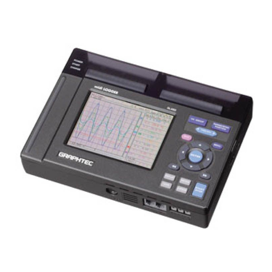
Checks and Preparation 2.3 GL450 Part Names and Functions This section describes the names and function of parts of the GL450 Monitor Control panel keys Data capture LED Battery charging LED Power LED Top panel External trigger Input terminal 2... -
Page 19: Monitor Part Names And Functions
Trigger settings ....Displays the trigger information. PC card access display ..The display flashes while data on the PC card is being accessed. Key lock ......Lit when the GL450 is in key lock status. To enable key lock status, hold down the [ ] key for at least three seconds. -
Page 20: Control Panel Key Part Names And Functions
Checks and Preparation 2.5 Control Panel Key Part Names and Functions This section describes the control panel keys. RANGE/SPAN/POSITION CH GROUP RANGE SPAN CH GROUP POSITION TIME/DIV TIME QUIT MENU QUIT MENU LOCAL Direction keys ENTER ENTER REVIEW DISPLAY DISPLAY REVIEW START START STOP... -
Page 21: Connecting To A Pc
Checks and Preparation 2.6 Connecting to a PC The GL450 can be connected to a PC via a LAN cable or a USB cable. Connection Using a LAN Cable Use the LAN cable to connect the GL450 to a PC. -
Page 22: Connecting The Power Cable And Turning On The Power
Grounding cable (4) Plug the AC cable into the mains power outlet. (5) Press the power switch on the GL450 to the ON side to turn on the power. CAUTION Always connect the GND terminal and refer to the safety precautions. The GL450 must be grounded... -
Page 23: Connecting To A Dc Power Supply
(3) Connect the DC input side to the DC power supply. CAUTION Be sure to check the polarity of the wire tips when performing wiring. (4) Press the power switch on the GL450 to the ON side to turn on the power. -
Page 24: Using The Battery Pack (Option)
2.8 Using the Battery Pack (Option) The B-517 battery is the only battery type that can be used with the GL450. Use the battery pack for data back-up when the AC power supply is interrupted by a power failure or brownout. -
Page 25: Charging The Battery
• Approx. 4 hours Using the GL450 for Charging The battery pack is charged by mounting it in the GL450, and supplying it with AC power. (1) Mount the battery pack in the GL450 (see the previous section for the mounting procedure). -
Page 26: Inserting And Removing A Pcmcia Card
Checks and Preparation 2.9 Inserting and Removing a PCMCIA Card This section describes how to insert a PCMCIA card. CAUTION Adequate precautions against static electricity must be taken when handling PCMCIA cards. Inserting a PCMCIA Card Insert the PCMCIA card into the slot as far as it will go. Removing a PCMCIA Card Press the eject button next to the PCMCIA card slot so that the button protrudes. -
Page 27: Mounting And Removing The Input Terminal Unit
(1) Remove the cover from the input terminal mounting area. (2) As shown in the figure below, insert the input terminal unit in the GL450. At this time, be sure to check that the terminal unit is locked onto the connector. -
Page 28: Connecting The Signal Input Cables To The Input Terminal Unit
• 20-channel input terminal unit (mounted in the GL450) : 20TU • 50-channel input terminal unit (used outside the GL450) : 50TU Note: Each of these input terminal units has been designed for use with the GL450 model only. CHECKPOINT These input terminal units are for use with the GL450 model only. -
Page 29: Attaching The Input Cable
Checks and Preparation Attaching the Input Cable (1) Use the supplied screwdriver to loosen the terminal screw. (2) Insert the cable tips into the terminal to be used. (3) Use the supplied screwdriver to tighten the terminal screw. 2-14... -
Page 30: Precautions To Observe When Performing Measurement
Checks and Preparation 2.12 Precautions to Observe When Performing Measurement Please be sure to read the following carefully in order to prevent electric shocks or shorts. DANGER • Do not input voltages exceeding 30 VAC rms or 60 VDC to any of the individual analog input sections or between the analog input section and the main unit. -
Page 31: Noise Countermeasures
Connect the signal chassis GND and the measurement device chassis ground. Use a short, thick lead to connect the chassis GND of the measurement object to the GL450's chassis GND. It will be even more effective if the ground potentials are the same. -
Page 32: Logic/Alarm Functions
Checks and Preparation 2.14 Logic/Alarm Functions Connect the round connector of the logic alarm cable (B-513, option) to the logic Input/alarm output terminal on the GL450. Logic alarm cable (B-513: 2m) Logic Functions Item Description Number of channels Input voltage range 0 to +24V max. -
Page 33: Trigger/Pulse Functions
Checks and Preparation 2.15 Trigger/Pulse Functions External Trigger Functions Item Description Number of channels Input voltage range 0 to +24V max. (single-ended ground input) Threshold level +2.5V Hysteresis Approx. 0.5 V (+2.5 to +3 V) PULSE TRIG Pulse Functions Item Description Number of channels Input voltage range... -
Page 34: Connecting The Humidity Sensor
2.16 Connecting the Humidity Sensor Connect the + and - lead wires of the humidity sensor (the B-530 option) to the desired terminals, and then insert the round connector into the 5V OUT connector on the GL450. Humidity sensor +, – lead wires... -
Page 35: Setting The Date And Time
Checks and Preparation 2.17 Setting the Date and Time If you are using the GL450 for the first time, charge the internal rechargeable battery and then make the date and time settings. CAUTION If the GL450 is not used for a period of approximately three months, the internal rechargeable battery may be discharged and the date and time may revert to the initial settings. -
Page 36: Settings And Measurement
CHAPTER Settings and Measurement This chapter describes the setting and measurement procedures for the GL450. Basic Settings and Measurement Detailed Settings and Measurement Data Replay... -
Page 37: Basic Settings And Measurement
Settings and Measurement 3.1 Basic Settings and Measurement With the GL450, control panel keys are provided for easy measurement. RANGE SPAN (1) CH GROUP key (2) RANGE/SPAN/POSITION key CH GROUP POSITION (3) TIME/DIV key TIME QUIT MENU LOCAL (5) Direction keys... -
Page 38: Range/Span/Position Key
Settings and Measurement (2) RANGE/SPAN/POSITION key These settings can be made or changed for each channel individually, even while the GL450 is running or performing measurement. CHECKPOINT The monitor is used for monitoring the measurement status only, and its settings cannot be changed. In addition, the RANGE setting can only be changed if data has not been captured. -
Page 39: Time/Div Key
Settings and Measurement SPAN settings 20 mV 0.200 to 40.000 mV/F.S. 0.0200v4.000 V/F.S. 50 mV 0.50 to 100.00 mV/F.S. 0.050 to 10.000 V/F.S. 100 mV 1.00 to 200.00 mV/F.S. 10 V 0.100 to 20.000 V/F.S. 200 mV 2.00 to 400.0 mV/F.S. 20 V 0.200 to 40.000 V/F.S. -
Page 40: Direction Keys
Settings and Measurement (5) Direction keys Direction keys ( ) ..These keys move the cursor on the screen in the direction indicated. Direction keys ( ) ... Press these keys to scroll the memory data waveforms, move the cursor, and specify the position of input values on menu screens. Direction keys ( ) .. -
Page 41: Save Key
CAUTION Data can only be saved when there is a PCMCIA card inserted in the card slot. Data saved to the internal memory will be deleted when the GL450 is turned off. (9) CURSOR key When the REVIEW key has been pressed and the replayed data is displayed, the cursor key can be used to select three cursor modes. -
Page 42: Detailed Settings And Measurement
Settings and Measurement 3.2 Detailed Settings and Measurement The QUIT and MENU keys enable detailed settings to be made. RANGE SPAN CH GROUP POSITION TIME (1) QUIT key (2) MENU key QUIT MENU LOCAL ENTER DISPLAY REVIEW START STOP SAVE CURSOR (1) QUIT key Use the [QUIT] key for operations such as the ones described below. -
Page 43: Menu Key
Settings and Measurement (2) MENU key Press the MENU key to switch through the AMP, ANNO, DATA, ALM, FILE, I/F, OTHR and INFO setting menus. It can also be used to confirm details. ANNO DATA FILE OTHR INFO q q q q q AMP Settings Window AMP Menu Structure Setting Selections available... - Page 44 Settings and Measurement CHECKPOINT When the CH setting is ALL, the Input, Range and Filter settings are the same for all the channels in that group. Input ........Selects the input condition. Off: No signal input is accepted. Voltage: Used for measuring direct-current voltage. Temperature: Used for measuring temperature.
- Page 45 (f) Choose CHECKPOINT The Scaling operation is calculated using a ratio of the Meas. Value or EU Output Value settings. If a ratio value that the GL450 cannot process is specified, the message below appears. Out of input range [ENTER] Apply...
- Page 46 Settings and Measurement Color ........This parameter enables the automatically set value for each channel to be changed manually. Misc........For voltage settings, zero position adjustment can be performed automatically, and the zero position reset. Perform Auto Zero ADJ.: Moves the current 'pen' position to the origin point.
- Page 47 Settings and Measurement Pulse ........The signals that can be input to the pulse input terminal for data processing are Revol., Counts, and Inst. Modes: Select from OFF, Revol., Counts, and Inst. • Off: Input is disabled. • Revol.: Counts the number of pulses per second, and displays the values multiplied by 60 as rpm values.
- Page 48 OK : Select to save the input text. CAUTION If [ * * ] displayed on the screen, this indicates that text from the OPS022 software has been input in a format that cannot be displayed on the GL450 monitor. 3-13...
- Page 49 Settings and Measurement e e e e e DATA Settings Window Data capture, Data replay, and Statistical Calculation settings are made here. DATA Menu Structure Setting Selections available Setting method Record Settings 100, 200, 500ms 1, 2, 5, 10, 20, 30s ENTER→Select→ENTER •...
- Page 50 Settings and Measurement PC Card: Commercially-available PCMCIA cards can be used in the PC slot. The amount of data that can be saved to the card is determined by the card itself. (Please see Specifications for the types of card that can be used.) CHECKPOINT When the captured data is Binary data, the reference to use is 1 data = 2 bytes.
- Page 51 Settings and Measurement Auto Save ......When this parameter has been selected, a file is created for each data capture time. Off, 1, 3, 6, 12, 24 hours The maximum data capture time that can be selected depends on the sampling interval.
- Page 52 Trigger Start and Stop conditions until the START/STOP key is pressed. On: Repeated measurement Off: Single measurement operation CHECKPOINT If repeated measurement has been specified and Memory selected as the capture destination, data captured to the GL450's internal memory is overwritten. 3-17...
- Page 53 Settings and Measurement Condition settings Mode ........Determines the alarm output condition Off: The alarm function is disabled. Rising: An alarm is generated when the signal input rises to (or exceeds) the specified alarm level. Alarm generated CH.1 Falling: An alarm is generated when the signal input falls to (or falls below) the specified alarm level.
- Page 54 Settings and Measurement Pulse Sets the alarms for pulse input settings. These conditions can be set when they have been enabled in the AMP settings. Mode ........Sets the same conditions as for "Condition Settings". Please refer to "Condition Settings" in the previous section. Lower - Level- Upper ..
- Page 55 Settings and Measurement Stop ........Specifies the trigger condition that must be met in order to stop measurement. Off: No trigger is used. Instead, measurement is stopped by pressing the START/STOP key. Level: Measurement is stopped when the trigger condition is satisfied. Note: The Level condition is the level value set for the specified channel range set (voltage, temperature).
- Page 56 Settings and Measurement t t t t t FILE Settings Window Saves or loads the PCMCIA card settings or returns them to their factory default settings. Setting Selections available Setting method Save current settings Auto, User ENTER→Select→ENTER File name (when User) •...
- Page 57 Settings and Measurement Card Initialize ...... Reformats the PCMCIA card. Format: Select from Super Floppy and HDD-compatible format. Type: Select Quick Format or Normal Format. Volume Label: This parameter specifies the volume label of the card to be reformatted. Specify a volume label of up to 11 characters.
- Page 58 Sets a gateway for the network connection. CHECKPOINT Be sure to restart the GL450 after settings have been made or changed. If the GL450 is used as is, the computer connections may not be performed correctly. USB PC Card Drive Mode Inserting a PC card in the GL450's card slot and then connecting the GL450 to your computer via USB enables the GL450 to be used as an external PC card drive.
- Page 59 On: The waveforms are displayed on a grid. Off. Only the waveforms (without any grid) are displayed. Screen Saver ...... Turns off the display if the GL450 is not operated within the specified interval, thus prolonging the product life of the display.
- Page 60 Select On to prevent any misoperation during data capture. Power On Start ....Initiates measurement as soon as the GL450 is turned on. Disable: Disables the Power On Start function. Enable: Enables the Power On Start function.
- Page 61 Date/Time ......This parameter sets the date and time. When this setting is selected, a submenu appears for setting the date and time. Language ......This parameter sets the GL450's display language. Japanese: The display is in Japanese. English US: The display is in English.
- Page 62 Settings and Measurement i i i i i INFO Settings Window The GL450's system settings are displayed here. Use this window to check the version and other information. 3-27...
-
Page 63: Data Replay
Settings and Measurement 3.3 Data Replay Data captured at the GL450 can be replayed on the monitor, and waveform search, statistical calculation, and data save functions performed. Data replay selection screen REVIEW key • When a PC card is inserted in the card slot: The data replay menu is displayed. - Page 64 Settings and Measurement Setting Selections available Setting method Cursor Position Move to First Data ENTER Move to Last Data ENTER Move to Center ENTER Move to Selected Position • Selected method: Position, Time ENTER→Select→ENTER • Position Moved To (Position only) Between ENTER→Specify numeric value Upper and Lower Limit Values →ENTER...
- Page 65 Settings and Measurement Alarm Slope: Specify the generation condition for the alarm search. • Both: Both rising and falling • Hi: Rising only • Lo: Falling only Next Alarm Match/Prev. Alarm Match: Depending on whether Next or Prev. has been selected, matching data from the current cursor position to the next alarm position, or from the previous alarm position to the current cursor position is searched for and displayed.
-
Page 66: Software
CHAPTER Software This chapter describes the software installation. System Requirements Installing the USB Driver Connecting to a PC Installing OPS022 Setting the IP Address and Device ID Menu Configuration and System Settings PC Connection Settings Measurement Parameters Settings View Functions 4.10 Review Device 4.11 Review PC 4.12 Logic, Alarm Display... -
Page 67: System Requirements
Software 4.1 System Requirements Make sure that the computer on which you plan to install the software meets the following requirements. Item System requirements Windows 2000, XP Pentium 4, 1.7 GHz or higher Memory 256 MB or more 10 MB for installing software, additional space required for data storage Display 1024 x 768 resolution or higher, 65535 colors or more (16-bit or more) Other... -
Page 68: Installing The Usb Driver
Manager". (2) In the "Device Manager" window, open "USB (Universal Serial Bus) Controller". Confirm that "Graphtec DM/GL/WR Series USB Driver" is shown. Right-click it and select "Properties". (3) Updating the driver Select the "Driver" tab and click the "Driver Details" button. -
Page 69: Installing The Usb Driver
Software Installing the USB Driver This section describes how to install the USB driver. (1) Insert the GL450 User Guide CD-ROM provided as a standard accessory into the PC CD- ROM drive. (2) Connecting the GL450 to the PC. Connect the GL450 to the PC using the USB cable, and then turn the power on. - Page 70 Software choose the driver to install." and click "Next". (6) In the "Select the device driver you want to install for this hardware." window, click "Have Disk". (7) In the "Locate File" window, browse the CD-ROM, select "USB DRIVER" "GTCUSBR.INF" and click "Open".
- Page 71 Installing the USB driver (1) Starting the wizard Connect the USB cable to the PC and the GL450. The "Found New Hardware" wizard appears. (2) In the "Found New Hardware Wizard" window, select "Search for a suitable driver for my device (Recommended)"...
-
Page 72: Connecting To A Pc
Software 4.3 Connecting to a PC The GL450 can be connected to a PC via a LAN cable or a USB cable. Connecting Using a LAN Cable Use a LAN cable to connect the GL450 to a PC. LAN cable Connection Methods When connecting the GL450 to a PC directly, use a cross cable. -
Page 73: Connecting Using A Usb Cable
USB Driver" for the installation procedure. Connection Methods When connecting the GL450 to a PC directly, connect using an A-B type cable. USB cable (A-B type) When connecting via a network, use an A-B type cable and connect through a USB hub. -
Page 74: Installing Ops022
(4) Continue, following the instructions on the screen. CHECKPOINT Be sure to observe the following points when connecting the GL450 to a PC. • Do not connect any devices apart from a mouse or a keyboard to any of the other USB terminals on your PC. -
Page 75: Setting The Ip Address And Device Id
Software 4.5 Setting the IP Address and Device ID The GL450 Configuration Tools window is used to set the IP address, and Device ID. For details, see Chapter 3, "Settings and Measurement". IP address: Used when measuring via a network. -
Page 76: Menu Configuration And System Settings
Software 4.6 Menu Configuration and System Settings Starting the Software Click "Start" "Programs" "OPS022" to launch OPS022. Once started, the following window is displayed. (1) Connect (2) Review PC (3) Print (12) Settings (14) Stop (8) Meter View (9) Report View (13) Start (15) Review Device (16) EXIT... - Page 77 Software Menu Name Selections (6) Waveform View Single View, Dual View (during data capture only) (7) Digital View 1-20 to 81-100, 1-50, 51-100 (8) Meter View 1-20 to 81-100 (9) Report View View in EXCEL (10) Y-T Single View Display, Dual View Display, Y Axis Range 1, Y Axis Range 2, X-axis Display Width (11) X-Y (12) Settings Select CH: From 1-10 to 91-100...
- Page 78 • Output alarm when burn out (Alarm Number 4) • Temp Unit • AC Line Cycle • Power On Star • Store the setting conditions into GL450 • Synchronize PC and device clocks • Factory Default Setting Send E-Mail Send E-mail when alarm is generated, Mail Address, Comments,...
-
Page 79: Pc Connection Settings
When all the settings have been made, click the "OK" button to complete the setting operation. (3) Connect, Disconnect/Load Conditions, Save Conditions Connect: When the "Connect" button is clicked to connect the GL450 to the computer after the settings have been made, "OK" is displayed to indicate that the connection can be made. - Page 80 Software Disconnect: Click this button to cancel the connected status. If the GL450 is not connected and this button is clicked, the status display goes blank. Load Conditions: Click this button to load previously-saved settings. Save Conditions:Click this button to save the settings. Please specify the file name and save destination.
-
Page 81: Measurement Parameters Settings
Software 4.8 Measurement Parameters Settings Click the "Settings" button on the main menu to enable device and measurement parameters for the GL450 to be made. CHECKPOINT The GL450 settings are changed whenever the "OK" or "Apply" button is clicked in each setting menu. - Page 82 Software • Unit: The measurement unit is displayed during measurement. • All CH: Sets the Input, Range, and Filter values to the same values for all the channels in the displayed group. Click the "Set" button next to "All CH" to make the settings. (2) Logic/Pulse Settings Device Number: Specify which of the connected devices to use for logic input.
-
Page 83: X-Y Settings
Software X-Y Settings Specify a combination of the X channel with one of the Y channels to display measurement data in XY format. 10 combinations are provided. Disp.: On (Enabled), Off (Disabled) Select On for X-Y display of the selected combination. Line Color: Specify the colors X Axis: Specify the channel for displaying X-axis measurement data. -
Page 84: Span
Software Span Click the "Span" button on the main menu to enable Span settings to be made. (1) Select CH Specify a group or groups of channels in the range [1 to 10] through [91 to 100]. (2) Analog Span Settings Upper: Specify the upper limit value of the set range. -
Page 85: Scaling
Software Scaling Use the Scaling function to perform calculation functions on the measured values and the scaling values. (1) Select CH Specify a group or groups of channels in the range [1 to 10] through [91 to 100]. Meas. Output •... -
Page 86: Data
(1) Device Settings Sampling Interval: 100, 200, 500 ms, 1, 2, 5, 10, 20, 30 s, 1, 2, 5, 10, 20, 30 min, 1 h Specifies the sampling speed for the GL450. CHECKPOINT The maximum sampling interval that can be set is limited by the number of channels installed. -
Page 87: Alarm
Software Alarm (1) Select CH Specify a group or groups of channels in the range [1 to 10] through [91 to 100]. (2) Alarm Settings Function: Off, Hi, Lo, Win In, Win Out Specifies the condition for alarm generation. Upper: Specifies the Upper Limit Value for the condition specified in Function. -
Page 88: Trigger
Software Trigger The trigger Start/Stop settings are made here. Trigger Settings/Level Trigger Settings Start • Function: Sets the Data Capture Start condition. Off: No trigger is used. Instead, measurement is initiated by pressing the START/STOP key. Level: The start of measurement is triggered when the trigger condition is satisfied. Alarm: The start of measurement is triggered with the alarm condition is satisfied. -
Page 89: File
(3) Delete File Data captured at the GL450 can be deleted. Select the file you want to delete and then click the "Delete File" button to delete it. - Page 90 Select the devices for Synchronized measurement. (7) Path Select a data capture folder saved to the PCMCIA card in the GL450 card slot. (8) File Select a data capture file saved to the PCMCIA card in the GL450 card slot.
-
Page 91: Report
Software Report Daily or monthly reports can be generated during data measurement. (1) Report Daily Capture: Check this box to enable report data to be generated daily. Capture Interval: 1, 5, 10, 30 seconds, 1, 5, 10, 30 minutes A daily capture file is automatically created for the measured data according to the capture interval specified. - Page 92 Software • Start Cell: Specifies the start cell position on the export sheet. CHECKPOINT • Take care with the data sequence (No., Date, Ch1, Ch2, ..., CHN, Pulse, Logic, Alarm: CHN is determined by the number of data capture channels). •...
-
Page 93: Other
OPS022 software cannot be captured when the Power On Start function is used). CHECKPOINT • If Power On Start is used to activate the GL450 and then the device is connected using the OPS022 application, the OPS022 status is displayed during data capture (waveforms are not displayed). - Page 94 Software (11) Send E-mail Send E-mail when an alarm is generated: Check this box to enable this function. Mail Address: Email can be sent to five locations. Please set the addresses in accordance with your computer system. Comments: Comments can be recorded for each email setting to explain the contents. (Email is actually sent when an alarm is generated.) 4-29...
-
Page 95: Information
Software Information The device status control information is displayed. This information can be used for maintenance purposes, but it cannot be input directly. 4-30... -
Page 96: View Functions
When the measurement conditions have been set, waveforms are displayed even though "Finished" is displayed. However, when the GL450 is connected to a computer, the waveforms are monitored. If "Start" is selected in this status, the display changes to "Recording", and measurement starts according to the settings made in the setting menus. -
Page 97: Waveform View
Software Waveform View The waveform view "Y-T" display can be selected as "Single View" or "Dual View". When the GL450 is in on-line status, the measured waveforms are always displayed. Moreover, when data capture has been started, the data is captured according to the settings made in the setting menus. - Page 98 Software (2) Dual View Display Data captured in the past can be displayed alongside the data that is currently being captured. Note: This function can only be used while data is being captured. Past data can be enlarged and checked using the on-screen cursors. When the display is Dual View, the cursor Cursor, Enlarge/Compress, display can be used to search data.
-
Page 99: Digital View
(1) 20-channel group displays: 1 to 20, 21 to 40, 41 to 60, 61 to 80, 81 to 100. (2) 50-channel group displays: 1 to 50, 51 to 100. CHECKPOINT Only the channels in the input terminal units that are installed in the GL450 are displayed. "*****" is displayed for channels that are not installed. 4-34... -
Page 100: Meter View
Software Meter View The measured data is displayed in a meter format. Use this view when you want to monitor the status with the feeling of using an analog meter. Moreover, this display can be changed in group lots. CHECKPOINT The alarm setting ranges are displayed in red in the Meter View screen. -
Page 101: Report View
Software Report View If the Daily Capture Processing and Monthly Capture Processing checkboxes in SettingsňReport were checked, the captured data is displayed on the screen in daily capture processing intervals. Moreover, the daily capture and monthly capture data are saved in the specified format. CHECKPOINT To change the setting, change the "Capture Interval"... -
Page 102: Review Device
Software 4.10 Review Device Use this function to replay the data captured at the GL450. The captured data can be replayed when the GL450 is in online status. Put the GL450 in online status, insert a PCMCIA card in the PCMCIA card slot, and then click the "Review Device"... - Page 103 Software (2) Select the file to be displayed. The data is displayed on the screen. If waveforms are displayed, the data can be checked and converted if required. • The capture Start Time, Capture Time, and Capture Interval are displayed at the upper right of the screen.
-
Page 104: Superimpose/Link
Note: Use this format if you want to replay the captured data via the OPS022 software. CSV: A TXT format for processing data in Excel. Note: If the CSV file was created using the OPS022 software or at the GL450, it can be opened via the OPS022 software. -
Page 105: Display In Excel
Software Display in EXCEL This function displays the captured data being displayed in Excel format. CHECKPOINT This function cannot be used unless the Microsoft Excel software program is installed in your computer. (1) Data All: All the measured data is converted. Cursors: Only the data between the A and B cursors is converted. -
Page 106: Xy Between Cursors Function
Software XY Between Cursors Function This function enables data in the range of Cursors A and B to be displayed as an XY waveform. Calculation This function enables data in the range of Cursors A and B to be displayed as Maximum, Minimum, Average, and P-P values for each channel. -
Page 107: Review Pc
Software 4.11 Review PC This function replays the data captured in the computer. Data can be replayed in online or offline status. Replay the data captured in the computer. Click the "Review PC" button to display the Review PC submenu. Opening a File (1) Click the "Open File"... - Page 108 Software (2) Select the file to be displayed, and then click the OK button. If waveforms are displayed, the data can be checked and converted if required. • The capture Start Time, Capture Time, and Capture Interval are displayed at the upper right of the screen.
-
Page 109: Superimpose/Link
Software Superimpose/Link The procedure for using the Superimpose and Link functions is the same as for "Review Device". Please refer to Section 4.10, "Review Device". Convert Then Save The procedure for converting the displayed data is the same as for "Review Device". Please refer to Section 4.10, "Review Device". -
Page 110: Logic, Alarm Display
Software 4.12 Logic, Alarm Display When the GL450 is in online status, the logic (4 channels) and alarm (4 channels) status can be monitored on-screen. Logic data can also be monitored as waveforms. Alarm log Screen Logic Display Alarm Display... -
Page 111: Specifications
CHAPTER Specifications This chapter describes the basic specifications for the GL450. Standard Specifications Function Specifications Accessory/Option Specifications External Dimensions... -
Page 112: Standard Specifications
Specifications 5.1 Standard Specifications Standard Specifications Item GL450 Number of analog input 2 units (10 channels x 2 or 20 channels x 2) terminal units mountable External input/output Trigger input, Logic input, Pulse input, Alarm output, synchronized main unit signals (sampling, trigger, etc.) PC interface Ethernet (10 Base-T/100 Base-TX);... -
Page 113: Pc Interface
Description Interface types Ethernet (10 Base-T, 100 Base-TX) USB (Ver. 2.0) Functions Data transfer to the PC (realtime, memory) PC control of the GL450 Realtime data transfer speed 0.1 s (10 ch) maximum Monitor Item Description Display 4.7-inch STN color LCD (320 x 240 dots) -
Page 114: Input Unit Specifications
Specifications Input Unit Specifications Item Description Number of input channels 10 channels/terminal unit (2 units mountable for a maximum of 20 channels) Input method Photo MOS relay scanning system; all channels isolated Scan speed 0.1s/10 ch maximum Measurement ranges Voltage: 20, 50, 100, 500 mV; 1, 2, 5, 10, 20, 50 V; 1-5 V F.S. Temperature •... - Page 115 Specifications Item Description Measurement accuracy Thermo Slot Measurement Temperature Measurement Accuracy (23°C ±3°C) couple Range ( ° (factory shipment status) when 30 minutes have Resistance Slot 1 Pt 100: –200 to 850 ±(0.05% of F.S +0.5°C) elapsed after the power Temperature JPt 100: –200 to 500 Pt: F.S = 1050°C...
-
Page 116: Function Specifications
Specifications 5.2 Function Specifications Standard Specifications Item Description Display screen Waveform display: Waveform screen + Digital screen, Waveform screen Digital display: Waveform screen + Digital screen, Calculation Display screen, Digital screen Note: Can be key-toggled Sampling interval* 100, 200, 500 ms; 1, 2, 5, 10, 20, 30 s; 1, 2, 5, 10, 20, 30 min; 1 h Waveform expansion Time axis: 1, 2, 5, 10, 20, 30 sec/Div /contraction... -
Page 117: External Input/Output Functions
Specifications External Input/Output Functions Item Description Input/output types Trigger input (1 ch), Logic input (4 ch), Pulse input (1 ch), Alarm output (4 ch) Input specifications Maximum input voltage: +24V Input threshold voltage: Approx. +2.5V Hysteresis: Approx. 0.5 V (+2.5 to +3 V) Alarm output specifications Output format: Open collector output (100 kΩ... -
Page 118: Accessory/Option Specifications
Specifications 5.3 Accessory/Option Specifications Control Software Item Description Compatible operating Windows 2000/XP system Functions Main unit control, realtime data capture, data conversion Main unit settings Input settings, memory settings, alarm settings, trigger settings Captured data Realtime data (CSV, Binary) Memory data (CSV, Binary) PC card data Display Analog waveforms, logic waveforms, pulse waveforms, digital values... -
Page 119: External Dimensions
Specifications 5.4 External Dimensions Dimensional precision: 5 mm ± Unit: mm... -
Page 120: Index
Index Index Sign 10-ch input terminal unit ........2-2 Calculation ............4-41 20-ch input terminal unit ........2-2 Capture 50-ch input terminal unit ........2-2 Destination ..........3-14 Start/Stop ............ 4-31 Time ............3-15 Card Initialize ........... 3-22 Adapter ............2-2 CD-ROM ............ - Page 121 Index Folder ............4-24 Connector ............. 2-3 Detailed Settings ..........3-7 Device I/F Settings Window ......... 3-23 ID ..............4-10 Number File ..........4-25 INFO Settings Window ........3-27 Number Other ..........4-28 Information ............4-30 Input ..............3-9 Settings ............4-21 Digital View ............
- Page 122 Index Condition settings ........3-18 Connector ............. 2-3 Logic ............3-19 LED ............... 2-3 Pulse ............3-19 On Start ..........3-25, 4-28 Monitor ............2-3, 5-3 Switch ............2-3 Area .............. 2-4 Print ..........4-36, 4-40, 4-44 Control dial ............ 2-3 Processing mode display area ......
- Page 123 ............2-5, 3-4 Statistical Calculation ........3-30 Y-T ..............4-32 Replay Settings ........... 3-16 Stop ..............3-20 Store the setting conditions into GL450 ... 4-28 Superimpose/Link ..........4-44 Synchronization connector terminal ....2-3 Synchronize PC and device clocks ........4-28 System Requirements ..........
- Page 124 The specifications, etc., in this manual are subject to change without notice. GL450-UM-151 June 27, 2005 2nd edition-01 GRAPHTEC CORPORATION...
- Page 125 503-10 Shinano-cho, Totsuka-ku, Yokohama 244-8503, Japan Tel : +81 (045) 825-6250 Fax : +81 (045) 825-6396 Email : info@graphteccorp.com Web : www.graphteccorp.com Printed in Japan...
Need help?
Do you have a question about the GL450 and is the answer not in the manual?
Questions and answers