Advertisement
Quick Links
Advertisement

Related Manuals for GRAPHTEC midi LOGGER GLT400


Summary of Contents for GRAPHTEC midi LOGGER GLT400
- Page 1 midi LOGGER GLT400 Quick Start Guide 604419040 GLT400-UM-851...
-
Page 2: Table Of Contents
Thank you for choosing Graphtec midi LOGGER GLT400. The Quick Start Guide is to assist you with basic operations. Please refer to the User's Manual (PDF) in the internal memory for more in-depth information. For details on how to refer to the User's Manual, see the "User's Manual and Supplied Software"... -
Page 3: User's Manual And Supplied Software
If you have deleted the User's Manual or supplied software from the internal memory, please download them from our website. Graphtec website: http://www.graphteccorp.com How to copy supplied files in USB DRIVE mode Set the Mode switch on the GLT400 to When the internal memory of the "USB DRIVE"... -
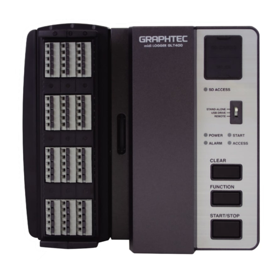
Page 4: Nomenclature
Nomenclature 15 16 1. Power switch 2. Protective cover holder 3. CLEAR key When you press briefly, the error condition is cleared. When you press and hold for 2 seconds, the alarm generation status is cleared. 4. FUNCITON key Press and hold for 2 seconds while capturing is stopped to perform wireless LAN easy connection (WPS). - Page 5 6. POWER LED This LED is lit in three colors: green, orange, and red. It mainly indicates the power state. Mode Switch state Lighting state Description STAND-ALONE / REMOTE Not lit Power off state Flashes in green Starting up/Reading setting file SD CARD replaceable state (during capturing) Lit in green When the GLT400 is started...
- Page 6 11. Mode switch The Mode switch is used to switch to one of three modes: STAND-ALONE, USB DRIVE, REMOTE. Switch the Mode switch when the power of the GLT400 is Off. The mode is not switched even if the Mode switch is switched when the power of the GLT400 is On.
-
Page 7: Connection Procedures
Connection Procedures Connect the AC adapter Connect the ground cable Connect the DC output of the AC adapter to Connect the ground cable to the GLT400 the connector marked "DC LINE" on the while pushing the button above the GND GLT400. - Page 8 Connect the expansion terminal base connection terminal <Screw terminal> DC voltage input Thermocouple input CH20 DC voltage Compensating lead wire Resistance bulb input DC current input Shunt resistance Lead wire resistance for 1 Example: In the case of 4-20 mA, apply line 250Ω...
- Page 9 Mounting SD CARD <How to mount> <How to remove> Remove the SD CARD protective cover. Insert the SD CARD until it clicks and is firmly placed . The SD CARD is released by inside the slot. pushing gently on the SD * Confirm that the writing is not locked.
-
Page 10: Safety Guide For Using Glt400
Safety Guide for using GLT400 If a voltage exceeding the specified value is input, the semiconductor relay used in the input section is damaged. Never input the voltage exceeding the specified value at any moment. Maximum input voltage of standard terminal (B-564) and screwless terminal (B-564SL) <... - Page 11 Unused channels The analog input section of the GLT400 contains a capacitor to improve the noise removal capability. Therefore, when the input terminal is in open sate, the measurement result may be affected by the signals of other channels. In such a case, set the input to "Off" or short between +/- terminals.
-
Page 12: Supplied Software
Supplied Software Two types of software applications for Windows OS are provided on this GLT400. Please use it according to the purpose. • Use the "GLT 400 Setting App" to change the settings. • Use "GL-Connection" to check the waveform of the input signal in real time or to capture the input signal. -
Page 13: The Ability To Interface With Gl840
The ability to interface with GL840 GLT400 Remote Mode By communicating with the midi LOGGER GL840 series via a wired LAN/wireless LAN connection, you can use the GL840 as the base unit and the GLT400 as the Remote Unit (remote terminal) for batch capturing on the GL840 base unit. Maximum 5 units, up to a total of 200 channels including the number of channels of GL840, can be captured at the same time. -
Page 14: Specifications
Specifications <Standard specifications> Items Description Number of analog Up to 200 channels can be used with maximum 10 units channels (In REMOTE mode, up to 180 channels can be used with maximum 9 units) External input and output Trigger input or External sample pulse: 1ch Logic input: 4ch or Pulse input: 4ch (in STAND-ALONE mode only) Alarm output: 4ch (only 1ch in REMOTE mode) Ethernet (10BASE-T/100BASE-TX), USB 2.0 (compatible with high... - Page 15 <External input/output functions> Items Description Input specifications Maximum input voltage: 0 to +30V (single-ended ground input) (Pulse/Logic/Trigger/Ex- Input threshold voltage: approx. +2.5V ternal sampling) Hysteresis: approx. 0.5V (+2.5V to +3V) Alarm output specifica- Output format: Open collector output tions (5V pull-up resistance 10kΩ) <Common specifications of the terminal in the input section>...
- Page 16 <Specifications of input section > (Standard terminal: B-564/Screwless terminal: B-564SL) Items Description Standard Number of 20 channels, M3 screw type input terminal channels, Screwless 20 channels, Screwless terminal Method terminal • Measurement accuracy Voltage: ±0.1% of F.S. • (23°C ±5°C) Thermocouple •...
- Page 17 <Specifications of input section > (Withstand high-voltage high-precision terminal: B-565) Items Description Number of input channels, Method 20 channels, M3 screw type • • Measurement accuracy Voltage : ± (0.05% of F.S. +10 μV) Thermocouple (23°C ±5°C) Type Measurement Measurement accuracy •...
- Page 18 Specifications are subject to change without notice. January 20, 2021 GLT400 Quick Start Guide 1st edition-01 (GLT400-UM-851) Publisher GRAPHTEC CORPORATION...
Need help?
Do you have a question about the midi LOGGER GLT400 and is the answer not in the manual?
Questions and answers