
Subscribe to Our Youtube Channel
Related Manuals for HP HP 83206A


Summary of Contents for HP HP 83206A
- Page 1 HP 83206A TIA/EIA-136 Cellular Adapter User’s Guide HP Part Number 83206-90002 Revision H Printed in U.S.A. October 1999 © Copyright Hewlett-Packard Company, 1998...
- Page 2 Notice Information contained in this document is subject to change without notice. All Rights Reserved. Reproduction, adaptation, or translation without prior written permission is prohibited, except as allowed under the copyright laws. This material may be reproduced by or for the U.S. Government pursuant to the Copyright License under the clause at DFARS 52.227-7013 (APR 1988).
-
Page 3: Manufacturer's Declaration
Manufacturer’s Declaration This statement is provided to comply with the requirements of the German Sound Emission Directive, from 18 January 1991. This product has a sound pressure emission (at the operator position) < 70 dB(A). • Sound Pressure Lp < 70 dB(A). •... -
Page 4: Safety Considerations
Safety Considerations GENERAL This product and related documentation must be reviewed for familiarization with safety markings and instructions before operation. This product has been designed and tested in accordance with IEC Publication 1010, "Safety Requirements for Electronic Measuring Apparatus," and has been supplied in a safe condition. This instruction documentation contains information and warnings which must be followed by the user to ensure safe operation and to maintain the product in a safe condition. - Page 5 Safety Considerations for this Instrument This product is a Safety Class I instrument (provided with a WARNING protective earthing ground incorporated in the power cord). The mains plug shall only be inserted in a socket outlet provided with a protective earth contact. Any interruption of the protective conductor inside or outside of the product is likely to make the product dangerous.
- Page 6 fuse(s) only with 250 V fuse(s) or the same current rating and type (for example, normal blow or time delay). Do not use repaired fuses or short circuited fuseholders.
-
Page 7: Product Markings
Always use the three-prong ac power cord supplied with this product. Failure CAUTION to ensure adequate earth grounding by not using this cord may cause product damage. This product is designed for use in Installation Category II and Pollution Degree 2 per IEC 1010 and IEC 664 respectively. For indoor use only. This product has autoranging line voltage input, be sure the supply voltage is within the specified range. - Page 8 HP will replace software media which does not execute its programming instructions due to such defects. 3. HP does not warrant that the operation of HP products will be uninterrupted or error free. If HP is unable, within a reasonable...
- Page 9 8. HP will be liable for damage to tangible property per incident up to the greater of $300,000 or the actual amount paid for the product that is the subject of the claim, and for damages for bodily injury or...
-
Page 10: Declaration Of Conformity
Department ZQ/Standards Europe, Herrenberger Strasse 130, D-71034 Böblinger, Germany (FAX+49-7031-14-3143) Hewlett-Packard Co. Spokane Division 24001 E. Mission Avenue Liberty Lake, Washington 99019-9599 TIA/EIA-136 Cellular Adapter HP 83206A This declaration covers all options of the above product. November 20, 1995 Date Vince Roland/Quality Manager... - Page 11 Regional Sales and Service Offices Eastern USA Sales Office Hewlett-Packard Company 2101 Gather Rd. Rockville, MD 20850 Tel: (301) 258-2000 Southern USA Sales and Service Hewlett-Packard Company 1995 North Park Place Atlanta, GA 30339 Sales Tel: (404) 955-1500 Fax: (404) 980-7292 Service Tel: (404) 850-2544 Fax: (404) 980-7292...
- Page 12 Asia Sales and Service Hewlett-Packard Asia Ltd. 22-30/F Peregrine Tower Lippo Center 89 Queensway, Central Hong Kong G.P.O. Box 863 Hong Kong Telephone: 852-848-7777 Fax: 852-868-4997 Australia, New Zealand Sales and Service Hewlett-Packard Ltd. P.O. Box 221 31-41 Joseph Street Blackburn, Victoria 3130 Telephone: (61/3) 895-2895 Fax: (61/3) 898-9257...
-
Page 13: Table Of Contents
Contents 1 Getting Started About the Cellular Adapter 32 Get ready to test 33 Described In this Chapter 33 Connecting the Cellular Adapter to the Test Set 34 Getting the Test Set to a Known State 34 Selecting the Proper Notch Filter for Audio Measurements 34 Zeroing the Average Power Meter 35 Going to the TIA/EIA-136 CALL CONTROL Screen 37... - Page 14 CALL CONTROL Screen 53 CALL CONFIGURE Screen 54 DIGITAL MEASUREMENT Screen 55 ANALOG MEASUREMENT Screen 56 Tasks You Can Perform with the Cellular Adapter 57 Call Processing Tasks 57 Measurements and Data available 58 Use the HP 8920 to Make Other Measurements 59...
- Page 15 Contents 3 Processing Calls About Call Processing Tasks and Measurements 62 PCS measurements 63 Configure the Test Set to Emulate a Base Station 64 How to know when the call is dropped 68 Call Processing Procedures 69 Authentication 70 Initialize Call Processing with Authentication 72 Page a Mobile Station with Authentication 74 Originate a Call with Authentication Perform an SSD Update 75...
- Page 16 Contents Choosing the proper combination of DVCC, slot, and channel number 92 Registration 93 Release by Mobile 95 Release by Test Set 96 Short Message Services 97 To Send a Short Message to the Mobile 97...
- Page 17 Contents 4 Making Measurements How to Read Data and Make Measurements 100 The Difference Between Data and Measurements 100 How to Switch Between Data and Meas Mode 101 Data Displayed 101 Connect State & Mobile Test Mode 102 Making changes to the Measurements display 107 How to determine if a call is dropped 111 Adjacent Channel Power 112 Analog Parameters 113...
- Page 18 Contents TX Power 139 Measuring Absolute TX Power on an AVC 140 Measuring Relative TX Power on a DTC 141 Measuring Average Power on an AVC or DTC with the PCS Interface 142 WER (DTC or DCCH) 143 How the Test Set measures WER 144...
- Page 19 Contents 5 Programming the Cellular Adapter Programming the Cellular Adapter 148 Programming in the Call Processing Subsystem 148 Program Example 149 Displaying the DCCH screens 154 Status Registers for DCCH Call Processing 155 Triggering and Remote to Local mode transitions 158 FACCH and SACCH programming 159 FACCH and SACCH description 159 Programming commands for FACCH and SACCH 159...
- Page 20 Contents 6 HP-IB Syntax Diagrams Overview 170 Diagram Conventions 171 DCCH 172 RF Path Control 192 Meas 193 SERV 198 Querying the Timebase Out-of-Lock Indicator 198 Checking if Temperature Compensation is Necessary 198 Integer Number Setting Syntax 199 Real Number Setting Syntax 200...
- Page 21 Contents 7 Screen and Field Descriptions The DCCH Call Processing Screens 206 DAMPS Call Processing 206 Parameters of the CALL CONTROL Screen 208 Parameter name 208 The CALL CONTROL screen 208 Access 209 Active 209 Amplitude 210 Band 210 CC Order 210 Chan 210 Connect 210 Cntl Order 211...
- Page 22 Contents # Systems 221 % BIT ERROR 221 Access Burst 221 BAND (Neighbor List) 221 Channel (Neighbor List) 221 Country Code 221 DCCH DVCC 222 Dig Signal 222 DTC Burst 222 Power Meter 222 PSID/RSID 222 Public Sys 223 RF Path 223 Reg Conf 223 Sat Tol 224 SMS Contents 224...
- Page 23 Contents Pwr Gain 230 Slot 231 Traffic Chan 231 Trig Type 232 Parameters of the ANALOG MEASUREMENT Screen 233 The ANALOG MEASUREMENT Screen 233 AF Anl In 233 AF Freq 234 AFGen1 Freq 234 AFGen1 To 234 Amplitude 234 De-Emphasis 234 Detector 235 Filter 1 235 Filter 2 235...
- Page 24 Contents RAND_U 242 1 of N 242...
- Page 25 Contents 8 Connector Descriptions Connector overview 244 Front Panel Connectors 245 Analyzer Baseband Data In 245 Analyzer Data Clock In 245 Analyzer Trigger In 246 Generator Baseband Data In 246 Rear Panel Connectors 247 Anl Trig Out 247 Bit Clk Out 247 Control I/O 247 CW RF In 248 Diag Out 248...
- Page 26 Contents 9 Troubleshooting General Operating Reminders 254 Remote Operation Considerations and Recommendations 257 Loopback BER 257 To Prevent Problems When Changing the System Type 257 Temperature Compensation 257 Handoffs 257 Releasing a Call 257 Going from the Data Display to the Measurement Display Mode 257 Changing from ANALOG MEAS Screen to CALL CONTROL Screen Measurements 258 Zeroing the Power Meter With a PCS Interface 258...
- Page 27 Contents 10 TIA/EIA-136 Basics What is TIA/EIA-136? 266 Basic Features of TIA/EIA-136 267 TIA/EIA-136 transceiver 268 The Transceiver Control Block 268 Modulation Methods 268 The Control Channels 268 TIA/EIA-136 Transceiver Block Diagram 270 Basic Functions of the DCCH in TIA/EIA-136 271 Power On and Initialization 271 DCCH Initialization Tasks 272 Call Origination 273...
- Page 28 Contents 11 Installing the Cellular Adapter Connecting the Cellular Adapter to the HP 8920 Series Test Set 286 I/Q Modulator and Relative TX Power Calibration 287 PCS Interface Connections 288 Connecting a Printer to the Serial Port 289...
- Page 29 Contents Glossary 291...
- Page 30 Contents Index 299...
-
Page 31: Getting Started
Test System to test a mobile transceiver. Use of the HP 83236B PCS Interface is also discussed. This manual is written for those who are already familiar with the HP 8920B RF Communications Test Set. If you want to learn more about using the Test Set... -
Page 32: About The Cellular Adapter
About the Cellular Adapter About the Cellular Adapter This Cellular Adapter is a test set adapter for the HP 8920B RF Communications Test Set. It works with the Test Set to test mobile transceivers built according to the TIA/EIA-136 standard. The Test Set and the Cellular Adapter are collectively referred to as the Test System. -
Page 33: Get Ready To Test
Make sure the Cellular Adapter, and PCS Interface (if used), and the Test Set are properly connected. If the PCS Interface is used, the HP 83236B System Connectivity test must be successfully completed before proceeding. Turn on the PCS Interface (if used), then turn on the Test Set. See “important: turning on the pcs interface”... -
Page 34: Selecting The Proper Notch Filter For Audio Measurements
Get ready to test Connecting the If you purchased the Test Set with the Cellular Adapter (Test Set Option 800 or Cellular Adapter to 801), they probably arrived completely assembled. If you need instructions to the Test Set make the connections between the Test Set and the Cellular Adapter, refer to Chapter 11, “Installing the Cellular Adapter,”... -
Page 35: Zeroing The Average Power Meter
Zeroing the TDMA Average Power can be measured if your Test Set is equipped with Average Power Option 006, or if you have a PCS Interface connected. If you are not using the Meter PCS Interface, you need to zero the average power detector in the Test Set first using the following procedure. - Page 36 Get ready to test HOW OFTEN A frequently zeroed Test System will ensure the highest measurement accuracy. SHOULD YOU ZERO The Zero Power function measures the input power with no cables connected to THE AVERAGE the Test System. The input power is measured for all gain settings. These POWER METER? measurements are stored in static RAM, and the Test System uses them to calculate any offsets when measuring power with a DUT attached.
-
Page 37: Call Control
Going to the In order to begin testing TIA/EIA-136 mobiles, the Test System must be at the TIA/EIA-136 CALL CONTROL screen. In this screen, you can select the TIA/EIA-136 system, CALL CONTROL control basic call processing functions, and make measurements. Screen How to access the TIA/EIA-136 CALL CONTROL screen 1. -
Page 38: Connecting A Mobile
TO THE ANT IN PORT Set. This will cause the overpower protection circuitry to activate when the mobile is ON THE FRONT transmitting. Refer to the HP 8920 RF Communications Test Set User’s Guide for more PANEL information. RF IN/OUT... - Page 39 RF IN/OUT Ä 83236B PCS INTERFACE Figure 6 Connecting a Mobile to the Test Set With the PCS Interface Chapter 1, Getting Started AUDIO OUT ANT IN AUDIO IN RF IN/OUT Antenna Microphone In Mobile Station Manufacturer’s Special Fixture Get ready to test Speaker Out...
-
Page 40: Testing Mobiles
Select Meas to start measuring (based on Test Set state) Read measurements Select other measurements, or change call processing states Programming either Measurements or tests? Manually perform tasks you want to program Map tasks to HP-IB commands Build and debug program... - Page 41 Chapter 1, Getting Started Get ready to test Chapter 2, “Product Description,” on page 49 Proceed to , to learn more about the Test Chapter 3, “Processing Calls,” on page 61 System’s features and operation. Go to , to Chapter 4, “Making Measurements,” on page 99 learn about call processing, to learn about measurements...
-
Page 42: Firmware Revision Needed For Pcs Testing
About the PCS Interface About the PCS Interface The HP 83236B PCS Interface can be used with the Test Set and Cellular Adapter to test TDMA mobiles in the cellular band (800 MHz to 900 MHz) and those operating in the North American PCS band (1850 MHz to 1990 MHz). The interface serves as the frequency up/down converter for the Test Set for PCS testing. -
Page 43: Chapter 1, Getting Started About The Pcs Interface
PCS interface. Be sure to set the HP-IB/Serial switch on the PCS Interface to the test. During the test, you are asked to select serial or HP-IB control of the interface. Select Serial Control and follow the remaining instructions displayed on the Test Set’s screen. -
Page 44: Installing The Pcs Interface
About the PCS Interface Using the PCS After installing the PCS Interface and successfully running the System Interface Connectivity test software, you need to perform some additional operations to properly use the interface. These operations include: 1. Initializing the PCS Interface for operation with the Test System. 2. - Page 45 These fields allow you to enter and enable or disable compensation for any path loss between the mobile and the PCS Interface’s RF IN/OUT port. Figure 8 Setting the PCS Mode control and entering PCS Interface path losses. Selecting RF OUT Only as the RF Output Port When the PCS mode is selected, the RF output of the PCS Interface can be directed to the RF OUT Only port on the PCS Interface.
- Page 46 About the PCS Interface Specifying the Type of Mobile Station You Are Testing: Even though you may be operating a PCS-compatible phone in the cellular band, it still uses the PCS protocol to perform call processing. You can also test non-PCS phones through the PCS Interface, so you still need to tell the test set what type of mobile you are testing.
- Page 47 See Diagrams,” on page 169 for a listing of all programming syntax for the Cellular Adapter. Chapter 1, Getting Started About the PCS Interface Chapter 6, “HP-IB Syntax...
- Page 48 About the PCS Interface Selecting the Correct Vocoder Two different vocoder standards can be used to test mobiles: VSELP and ACELP. You need to select the proper vocoder for the mobile you are testing. This is done using the 1. Access the CALL CONTROL screen by highlighting the More field and selecting CALL CNTL from the list of choices.
-
Page 49: Product Description
Product Description This chapter shows the TIA/EIA-136 screens and explains their purpose. It also identifies features of the Cellular Adapter. -
Page 50: Purpose Of This Cellular Adapter
Communications Test Set enables testing of the following cellular systems: TIA/EIA-136 (DCCH), TIA/EIA-627 (DAMPS or TDMA), and AMPS. This Cellular Adapter contains the hardware and firmware necessary to test DCCH and DAMPS. The AMPS hardware and firmware is contained in the HP 8920. Table 1 DAMPS and DCCH Channels... -
Page 51: The Dcch Call Processing Screens
Chapter 2, Product Description The DCCH Call Processing Screens The DCCH Call Processing Screens The Cellular Adapter provides a set of screens which emulates a cellular base station. This set of screens for DCCH is called the DCCH Call Processing Subsystem. - Page 52 The DCCH Call Processing Screens CALL CONTROL - Connect mode measurements: EVM, Adj Ch Power, Average Power, MAHO, phase error, magnitude error, origin offset, droop, sync location, frequency error TX power, AF frequency, FM deviation - measures DCCH, ACC, DTC, AVC - control call processing To Screen CALL CNFG...
-
Page 53: Call Control Screen
CALL CONTROL The CALL CONTROL screen is the primary screen of the DCCH Call Processing Screen Subsystem. It controls call setup and maintenance functions for base station emulation. From this screen, you can set basic parameters of the channel, such as Phone Number, Control Channel Number, Amplitude, Voice Channel, and Power Level. -
Page 54: Call Configure Screen
The DCCH Call Processing Screens CALL The CALL CONFIGURE screen provides additional controls for TIA/EIA-136 CONFIGURE features. Refer to the field descriptions in Screen on page 205 No data or measurements are displayed on the CALL CONFIGURE screen. The Test Set can be in Connect mode, but no call processing actions can be taken here. These are the controls available in this screen: •... -
Page 55: Digital Measurement Screen
DIGITAL This screen enables measurements on a DTC (Digital Traffic Channel) by using MEASUREMENT the Mobile Station Test Interface, as specified in TIA/EIA Interim Standard Screen IS-137. It also supports the TIA/EIA-627 Test Interface. Refer to the field descriptions in information. -
Page 56: Analog Measurement Screen
The DCCH Call Processing Screens ANALOG This screen allows you to make measurements on an AVC (Analog Voice MEASUREMENT Channel). These measurements are the same as the AMPS Analog Measurement Screen screen. Refer to the field descriptions in on page 205 Figure 15 The ANALOG MEASUREMENT Screen S:\HP83206A\USRGUIDE\MANUAL\opovervw.fm... -
Page 57: Tasks You Can Perform With The Cellular Adapter
• Calling number • Access and DTC burst variations • Unique programming of FACCH and SACCH messages (via HP-IB only) • Send Short Message Service messages to the mobile. • Send Caller ID messages to the mobile. Chapter 2, Product Description... -
Page 58: Measurements And Data Available
Tasks You Can Perform with the Cellular Adapter Measurements and The following measurements can be made with the Cellular Adapter. Data available • EVM1 (Error Vector Magnitude, measured over 1 time slot) • EVM10 (EVM of first 10 bits of 10 bursts, averaged) •... -
Page 59: Use The Hp 8920 To Make Other Measurements
Use the HP 8920 to Make Other Measurements Use the HP 8920 to Make Other Measurements This TIA/EIA-136 product is attached to a fully functioning HP 8920B. You can use the Test Set for all of your analog measurements, including AMPS call processing. - Page 60 Chapter 2, Product Description Use the HP 8920 to Make Other Measurements S:\HP83206A\USRGUIDE\MANUAL\opovervw.fm...
-
Page 61: Processing Calls
Processing Calls This chapter explains how to use the DCCH Call Processing screens to perform call processing tasks such as pages, originations, registrations, and so on. -
Page 62: About Call Processing Tasks And Measurements
About Call Processing Tasks and Measurements About Call Processing Tasks and Measurements The Call Processing subsystem of the HP 8920 and Cellular Adapter can be set up to emulate a TIA/EIA-136 standard base station. Primary call processing tasks such as registrations, pages, handoffs, and releases can be made with just one screen: the CALL CONTROL screen. -
Page 63: Pcs Measurements
PCS measurements PCS measurements PCS compatible mobiles are tested using the HP 83236B PCS Interface connected to the Test System. After the interface is connected and some controls are set to indicate its presence in the system, you can proceed to test PCS-compatible mobiles the same way you test non-PCS TIA/EIA-136 mobiles. -
Page 64: Configure The Test Set To Emulate A Base Station
Configure the Test Set to Emulate a Base Station Configure the Test Set to Emulate a Base Station Before you can use the Test Set to perform call processing tasks, it must be configured to emulate the base station. Use the following procedures to prepare the Cellular Adapter to emulate a base station. - Page 65 CAUTION: SAVING To use SAVE/RECALL registers, you must use the same hardware configuration present SETTINGS FOR PCS at the time the register is created. If you save instrument settings when a PCS Interface is OPERATION connected to the Test Set, the Test Set expects to detect the presence of the interface when the register is recalled.
- Page 66 Configure the Test Set to Emulate a Base Station Define the settings for the traffic channel that you want your mobile to be assigned to when establishing a call: • Choose DTC to set up a Digital Traffic channel. • •...
-
Page 67: Chapter 3, Processing Calls Configure The Test Set To Emulate A Base Station
Chapter 3, Processing Calls Configure the Test Set to Emulate a Base Station D. Put the Test Set in Active state to emulate a base station 1. Select Active from the list on the left side of the screen. 2. The Active annunciator lights up when the Test Set is emulating a base station. When the base station emulation is on, this annunciator... -
Page 68: How To Know When The Call Is Dropped
Configure the Test Set to Emulate a Base Station How to know when There are several ways the Test Set notifies you when a call has been dropped. the call is dropped Any of the following situations may occur. Connect state ends If the Connect annunciator goes off, and the Test Set returns to the Active state, the call has dropped or ended. -
Page 69: Call Processing Procedures
Call Processing Procedures You can use the procedures in this chapter to test your mobile station. In the following list, the most commonly used procedures are listed first. The procedures are presented alphabetically by procedure name. “Registration” on page 93 •... -
Page 70: Authentication
Authentication Authentication The process of testing DCCH authentication (TIA/EIA-136) through the Call Processing Subsystem requires the user to synchronize the base station and mobile station. This synchronization requires that the base station and the mobile station possess two pieces of shared secret data (SSD) to confirm a valid call. The first piece is the . - Page 71 The above settings are used when the mobile is camped on a DCCH, or is connected on a DTC. Figure 17 Authentication Screen Differences authen_scrn.tif The above settings are used when the mobile is connected on an AVC. Chapter 3, Processing Calls Authentication authen.pcx...
-
Page 72: Initialize Call Processing With Authentication
Authentication Initialize Call Processing with Authentication There are two methods to initialize Call Processing with authentication. • Initializing Call Processing with Authentication through registration with the Test Set. • Initializing Call Processing with Authentication without registration with the Test Set. Initialize Call Processing with Authentication through Registration 1. -
Page 73: Chapter 3, Processing Calls Authentication
Initializing Call Processing with Authentication without Registration 1. On the CALL CONTROL screen, set the System Type to DCCH and verify that the Active annunciator is lit. 2. Connect the mobile station to the Test Set as shown in 3. Turn on the mobile station. 4. -
Page 74: Page A Mobile Station With Authentication
Authentication Page a Mobile Station with Authentication Paging A Mobile Station That Has Registered With The Test Set 1. Register the mobile with the Test System. See Authentication through Registration” on page 72 2. Select the Page field. The Page annunciator lights while the Test Set pages the mobile on the forward control channel. -
Page 75: Perform An Ssd Update
Perform an SSD Update There are two methods that can be used to perform an SSD Update: • SSD Update on the Control Channel • SSD Update on the Voice Channel Performing an SSD Update on the Control Channel 1. Ensure that the Test Set has Initialized Call Processing with Authentication. See “Initialize Call Processing with Authentication through Registration”... - Page 76 Authentication Performing an SSD Update on the Voice Channel A registered mobile can be paged to go to either a digital traffic channel (DTC) or an analog voice channel (AVC). The type of channel assigned depends on the Voice Channel Assignment - Type paged.
-
Page 77: Perform A Unique Challenge
Perform a Unique Challenge There are two methods that can be used to perform a Unique Challenge-Response procedure: • Unique Challenge on the Control Channel • Unique Challenge on the Voice Channel Performing a Unique Challenge on the Control Channel 1. - Page 78 Authentication Performing a Unique Challenge on the Voice Channel 1. Ensure that the Test Set has Initialized Call Processing with Authentication. See “Initialize Call Processing with Authentication through Registration” on page for information on how to register the mobile station and activate Authentication. 2.
-
Page 79: Processing Calls Caller Id
Caller ID Caller ID sends a specially formatted message to the mobile under test that identifies the phone number and name of the person calling. The Caller ID fields are located on the DCCH CALL CONFIGURE II screen. 1. Select CALL CFG2 from the CALL CONTROL’s To Screen. 2. -
Page 80: Country Code
Country Code Country Code You can define the country code with this field. Mobile Country Code (MCC) assignments are as described in CCITT Recommendation E.212. Table 2 Some Mobile Country Codes Code 310-316 234-235 1. select CALL CNFG from the CALL CONTROL’s To Screen. 2. -
Page 81: Downbanding
Downbanding Downbanding is a specialized function which enables the Test Set to work in a band just below the cellular band. By choosing the downband (Band 10) function, the Test Set emulates a base station with channels numbered 1-600, in the frequency band 851 - 869 MHz. -
Page 82: Facch Sacch Programming
Control CHannel) is used to transmit from the base to the mobile, and SACCH (Slow Associated Control CHannel) is used to transmit from the mobile to the base. These channels are controlled in the Test Set via HP-IB programming only. Refer “FACCH and SACCH programming” on page 159 Syntax Diagrams,” on page 169 S:\HP83206A\USRGUIDE\MANUAL\cpmeas.fm... -
Page 83: Processing Calls Handoff
4. When the handoff is complete, the data for the new DTC or AVC will be displayed on the screen in the left side of the Traffic or Voice Chan Assignment area. Chapter 3, Processing Calls Handoff for an example of the equivalent HP-IB “Page” on page 91... -
Page 84: Choosing The Proper Combination Of Dvcc, Slot, And Channel Number
Handoff Select These are the parameters that the mobile has before the handoff. Figure 20 CALL CONTROL Screen with Handoff Data Displayed Choosing the The TIA/EIA-136 specification indicates that on any single RF channel, the proper combination DVCC for all slots must be the same. For example, if your DCCH is assigned to of DVCC, slot, and channel 42, and you assign the mobile to a DTC of 42, then the DVCC for both channel number... - Page 85 What you should do: • Don’t use the same RF channel number for both DCCH and DTC. • If you need to use the same RF channel number for both, then verify that the • slot number of the number of the DCCH (1 or 4), and DTC slot •...
-
Page 86: Maho
Chapter 3, Processing Calls MAHO MAHO For details about mobile assisted handoff (MAHO) see “MAHO” on page 124. S:\HP83206A\USRGUIDE\MANUAL\cpmeas.fm... -
Page 87: Processing Calls Message Waiting Indicator
Message Waiting Indicator Message Waiting Indicator (MWI) sends a command to a mobile to tell it that one or more messages are waiting to be read or listened to. The mobile can either be camped on a DCCH or be connected to a DTC to receive the message. Send MWI fields of the CALL CONFIGURE II screen. -
Page 88: Orders
Note that the available choices in the channel only. See command. (See also “Which Control Order Command Should I Use?” in the HP 8920B Option 801 Condensed Programming Reference.) 1. Verify that the Test Set is in the Connect state. (See 2. -
Page 89: Processing Calls Origination
Origination When the mobile originates a call, the Test Set automatically assigns the call to the DTC or AVC indicated on the CALL CONTROL screen. The number that the mobile has called is displayed. Read about choosing the proper DVCC, slots, and channel numbers in the proper combination of DVCC, slot, and channel number”... -
Page 90: Choosing The Proper Combination Of Dvcc, Slot, And Channel Number
Origination While the mobile is being signaled, this annunciator is lit. When the mobile is communicating on the correct voice channel this annunciator is lit. Figure 22 CALL CONTROL Screen After a Successful Origination Choosing the The TIA/EIA-136 specification indicates that on any single RF channel, the proper combination DVCC for all slots must be the same. -
Page 91: Chapter 3, Processing Calls Page
Page “Program Example” on page 149 1. Verify that you have already done the following (refer to Emulate a Base Station” on page 64 • Zeroed the RF Power meter • Put the Test Set in Active state • Connected the mobile to the Test Set and turned the mobile’s power on •... -
Page 92: Choosing The Proper Combination Of Dvcc, Slot, And Channel Number
Page Choosing the The TIA/EIA specification indicates that on any single RF channel, the DVCC for proper combination all slots must be the same. For example, if your DCCH is assigned to channel 42, of DVCC, slot, and and you assign the mobile to a DTC of 42, then the DVCC for both the DCCH and channel number the DTC must be the same. -
Page 93: Registration
Registration “Program Example” on page 149 1. Verify that you have already done the following (refer to Emulate a Base Station” on page 64 • Zeroed the RF Power meter to your satisfaction. • Selected the proper audio filter, if you want to test audio. •... - Page 94 Registration DATA DISPLAYED The last two lines of data (Protocol Version and Model) are not displayed when the Test WHEN ON AN ACC Set is emulating a base station on an Analog Control Channel (ACC). S:\HP83206A\USRGUIDE\MANUAL\cpmeas.fm...
-
Page 95: Processing Calls Release By Mobile
Chapter 3, Processing Calls Release by Mobile Release by Mobile “Page” on page 91 1. Verify that the Test Set is in the Connect state. (See 2. Press the END button on the mobile. 3. When the release is complete, you will see the Connect annunciator turn off, and the Active annunciator turn on. -
Page 96: Release By Test Set
Release by Test Set Release by Test Set “Program Example” on page 149 1. Verify that the Test Set is in the Connect state (See 2. Select Release from the list on the left side of the screen. 3. When the release is complete, you will see the Connect annunciator turn off, and the Active annunciator turn on. -
Page 97: Processing Calls Short Message Services
Short Message Services Short Message Services (SMS) allow a short text message to be sent to the mobile. The mobile must either be camped on a DCCH or be connected on a DTC to receive the message. You can send a custom message or select all or part of a factory-defined message. - Page 98 Short Message Services Select Send SMS to send the SMS message (the name of this field is changed to Order if the mobile is connected on a call). S:\HP83206A\USRGUIDE\MANUAL\cpmeas.fm Use these three fields to define the SMS message. dcch_cc.tif Indication that the mobile has successfully received and decoded the SMS message.
-
Page 99: Making Measurements
Making Measurements This chapter discusses the difference between data and measurements. It also explains how to read data and make measurements. -
Page 100: The Difference Between Data And Measurements
Some measurements are listed below. Measurements • EVM1 (%) • adjacent channel power (dB) • BER (%) • Average Power (requires HP 8920B Option 006 or PCS Interface) • TX Power S:\HP83206A\USRGUIDE\MANUAL\meas.fm field. Data/Meas... -
Page 101: Data Displayed
How to Switch To switch between Data and Meas mode, select the Between Data and toggles between data and measurement modes. Meas Mode Select here to toggle between Data and Meas modes Figure 25 Switching Between Data and Measurements Data Displayed The data that is displayed when a mobile responds depends on the mobile’s status with respect to the Test Set. -
Page 102: Connect State & Mobile Test Mode
How to Read Data and Make Measurements Connect State & There are two methods of making measurements with the DCCH Call Processing Mobile Test Mode subsystem. Each method requires that the mobile be in a certain state, and each method uses a different screen. One method requires that the Test Set be in “Connect”... - Page 103 EVM1 Changes to TX Power (Avg) when a PCS Interface is used. EVM10 Adjacent Channel Power Average Power Not available when a PCS Interface is used. MAHO Figure 27 Connect State Measurements Available on a Digital Traffic Channel Chapter 4, Making Measurements How to Read Data and Make Measurements...
- Page 104 Chapter 4, Making Measurements How to Read Data and Make Measurements Figure 28 Connect State Measurements Available on a Analog Voice Channel S:\HP83206A\USRGUIDE\MANUAL\meas.fm...
- Page 105 Connect state measurements. The exception is that instead of MAHO, BER can be measured in this screen. Notice that ACCH is at the list of measurement choices. This function is only used under HP-IB operation. See Select here to choose between...
- Page 106 How to Read Data and Make Measurements Select Meas display measurements Figure 30 The Default Measurements Screen S:\HP83206A\USRGUIDE\MANUAL\meas.fm You can decide which measurements are displayed here These are the measurements you can choose Peak EVM Phase Err Mag Err Orgin Ofs Droop Sync Loc Max Abs...
- Page 107 Making changes to In the Connect state, when the Measurements displays the EVM1 measurements. When making measurements on a digital display traffic channel, there are four default selections for the EVM1 measurements: • Frequency Error • TX Power • • Peak EVM Default measurement selections...
-
Page 108: Average Power
How to Read Data and Make Measurements EVM1 EVM10 Adjacent Channel Power Average Power DCCH Figure 32 Test Mode Measurements Available (DIGITAL MEASUREMENT Screen) S:\HP83206A\USRGUIDE\MANUAL\meas.fm... - Page 109 Other changes you There are two other types of changes you can make to the Meas display: can make 1. the actual measurements displayed 2. the units of each measurement displayed Changing the measurements displayed When Meas Data/Meas appears. The list of choices allows more measurements such as EVM 10, Adjacent Channel Power, Average Power, and MAHO.
- Page 110 How to Read Data and Make Measurements Changing the units displayed The unit for a measurement is displayed to the right of the measurement name in the data display area. To change the unit, select the unit field, and then press the desired unit key on the front panel.
- Page 111 How to determine if There are several methods for using the Test Set to determine if a call has been a call is dropped dropped. Any of the following situations may occur. Connect state ends If the Connect annunciator goes off, and the Test Set returns to the Active state, the call has dropped or ended.
-
Page 112: Adjacent Channel Power
Adjacent Channel Power Adjacent Channel Power Adjacent Channel Power is measured in either Connect state or test mode.The measurement procedure described below is for the Connect state. To measure in the test mode, see Adjacent Channel Power measures the power on six adjacent channels. These are the three nearest channels both below and above the designated channel. -
Page 113: Analog Parameters
Analog Parameters Analog parameters are measured in either Connect state or test mode.The measurement procedure described below is for the Connect mode. To measure in the test mode, select the You can measure parameters of a TIA/EIA-136 mobile on its Analog Voice Channel (AVC). -
Page 114: Average Power
Average Power Average Power Average Power (DTC), and requires the use of the special average power detector that is only available with Test Set Option 006 (50 W to 10W Power Measurement Range). Average Power measurements are limited to this power range. Refer to Measurements”... - Page 115 Loopback BER can only be measured while the Test Set is in Active mode, and the mobile is in its test mode. This measurement is for raw BER, measured on a traffic channel. Each mobile manufacturer has their own method of enabling the test mode for their phones.
-
Page 116: How The Test Set Measures Raw Ber
BER Measurement with Inserted Bit Errors 1. Make sure the Test Set is in Active mode. 2. Select CALL CNFG from the To Screen menu. 3. Assign a global USER key to the % BIT ERROR field as follows: a Select the % BIT ERROR field. b Press the SHIFT key, then k4 (ASSIGN) key. - Page 117 Chapter 4, Making Measurements BER.tif Figure 37 BER Display Indicating a Mobile with a High BER for the Specified Amplitude...
-
Page 118: Digital Measurement Screen Tests
Digital Measurement Screen Tests Digital Measurement Screen Tests This screen allows you to test the DTC without requiring that the mobile and the Test Set be in the Connect state. This is achieved by utilizing the Mobile Station Test Interface as described in the TIA/EIA Interim specification IS-137. Basically, you start with the Test Set in Active state, display the DIGITAL MEASUREMENT screen, put your mobile into its IS-137 test mode, and test as usual. -
Page 119: Chapter 4, Making Measurements Digital Measurement Screen Tests
Chapter 4, Making Measurements Digital Measurement Screen Tests dig-meas.tif Figure 38 DIGITAL MEASUREMENT Screen Display... -
Page 120: Droop
Droop Droop Droop is measured in either Connect state or test mode.The measurement procedure described below is for the Connect state. To measure in the test mode, “Test mode measurement procedure” on page Droop measures the difference between the level of the first symbol and the level of the last symbol captured by the analyzer. - Page 121 EVM is measured in either Connect state or test mode. The measurement procedure described below is for the Connect state. To measure in the test mode, “Test mode measurement procedure” on page Error Vector Magnitude (EVM) measures the magnitude (rms) of the error vector between the measured and the ideal signal.
-
Page 122: Frequency Error
Frequency Error Frequency Error Frequency error is measured in either Connect state or test mode. The measurement procedure described below is for the Connect mode. To measure in the test mode, see TX frequency error measures the difference between the measured frequency and the frequency that the Test Set is tuned to. -
Page 123: Making Measurements Magnitude Error
Magnitude Error Magnitude error is measured in either Connect state or test mode. The measurement procedure described below is for the Connect state. To measure in the test mode, see Magnitude error is the difference in amplitude at the detector point between the measured value and the ideal value. -
Page 124: Maho
MAHO MAHO This measurement is available only from the CALL CONTROL screen in Connect state. MAHO (Mobile Assisted HandOff) is actually a measurement, not a handoff. The reported results are used by a base station to select the channel for the handoff. The mobile performs the measurements, and then reports the results back to the base station. - Page 125 Setting up the MAHO measurement 1. Select CALL CNFG from the CALL CONTROL’s To Screen. 2. Set the number of neighbors (up to 6) with the field # Neighbors. 3. Neighbor List Channel fields appear below the # Neighbors field. 4.
- Page 126 MAHO Measuring MAHO 1. From CALL CONTROL screen, set up a call (Test Set must be in Connect mode). 2. Select Meas from the Data/Meas field. 3. Select the field that has appeared below Data/Meas. 4. Select MAHO from the list of choices. 5.
- Page 127 Measuring MAHO BER with Inserted Bit Errors 1. Select the CALL CONTROL screen. 2. Set the Amplitude field to 50 dBm. 3. Allow the mobile to camp on the DCCH. 4. Bring up a call on a DTC, either by paging or origination. 5.
-
Page 128: Origin Offset
Origin Offset Origin Offset Origin offset is measured in either Connect state or test mode. The measurement procedure described below is for the Connect state. To measure in the test mode, “Test mode measurement procedure” on page Origin offset measures the magnitude of the RF carrier leakage relative to the magnitude of the modulated carrier at the detection point. -
Page 129: Making Measurements Phase Error
Phase Error Phase error is measured in either Connect state or test mode. The measurement procedure described below is for the Connect state. To measure in the test mode, “Test mode measurement procedure” on page Phase error is the difference in phase at the detection point between the received signal and an ideal signal. -
Page 130: Power Measurements
Power Measurements Power Measurements Transmitter power is measured when the Test Set is in the Connect state (the Connect the mobile is in its Test mode. Test Mode power measurements cannot be made on the CALL CONTROL screen, but can be made on the DIGITAL MEASUREMENTS, ANALOG MEAS, DUPLEX TEST, and RF ANALYZER screens. - Page 131 Table 3 Test Set Screens from which Average Power and TX Power of the DTC and AVC can be Measured With HP 83236B Power Measurement Type Screens: • Call Control TX Power (Avg) and •...
- Page 132 Power Measurements CALIBRATING THE Two calibration routines must be run when the Cellular Adapter is first connected to the RELATIVE Test Set and any time the Cellular Adapter is serviced and re-attached. One of these rou- TX POWER tines specifically calibrates the relative TX Power measurement, and must be run to ensure MEASUREMENT measurement accuracy.
- Page 133 Step 2 - Enter the channel number of the TDMA reference signal. Step 4 - Press SHIFT, REF SET, ENTER to set the present signal level to be the measurement reference level. All subsequent power measurements are relative to the indicated value. Notice that the Test Set now indicates that the displayed measurement is referenced to some other level.
- Page 134 This is the only way to measure the absolute (rms) power of a TDMA signal without using a PCS Interface. This measurement is not used if the HP 83236B PCS Interface is used. Once a burst is detected, the cellular adapter starts measuring power when the sixth symbol is received.
- Page 135 Zeroing the Before establishing a call, zero the average power meter by selecting the Average Power Meter Zero Average Power Meter” on page Meter typically 5% or 0.2dB. Understanding the is a measure of the power into the analog to digital converter (ADC) at Max Abs the input of the Cellular Adapter.
- Page 136 Power Measurements Measuring Average Power with the Mobile in Test Mode Select Avg Power Leave this set to Auto Figure 51 Average Power Measured on the DIGITAL MEASUREMENTS Screen with PCS Interface Disabled Select Avg Power. Figure 52 Average Power Measured on the DIGITAL MEASUREMENTS Screen with PCS Interface Enabled S:\HP83206A\USRGUIDE\MANUAL\meas.fm avg_pwr_std.tif...
- Page 137 Power Measurements TX Power (Avg) [W] This is an rms power measurement. It is only available when an HP 83236B PCS Interface is used. This measurement is similar to the Average Power measurement. In fact, the Average Power measurement is disabled if the PCS Interface is used because the interface can measure power for both Cellular and PCS signals.
-
Page 138: Sync Location
Sync Location Sync Location Sync location is measured in either Connect state or test mode.The measurement procedure described below is for the Connect state. To measure in the test mode, “Test mode measurement procedure” on page Sync location measures the time in number of bit periods from the trigger to the beginning of the first sync word detected. -
Page 139: Tx Power
TX Power Three types of Transmitter Power measurements are available: • TX Power [W] - to measure the absolute power of an Analog Voice Channel (AVC). • TX Power [dB] - To measure the relative power of a Digital Traffic Channel (DTC). This provides a way to measure transmitter power on a DTC when your Test Set does not have Option 006 (50 W to 10W Average Power Measurements) or a PCS Interface. -
Page 140: Measuring Absolute Tx Power On An Avc
TX Power Measuring To measure absolute TX Power when a mobile is in the Connect state, use the Absolute TX Power following measurement procedure. To measure absolute TX Power when the on an AVC mobile is in the Test mode, select display the ANALOG MEAS screen. - Page 141 Measuring Relative The following measurement procedure is for mobiles in the Connect state. Use the TX Power on a DIGITAL MEASUREMNTS screen to make measurements with the mobile transmitting in the test mode (see 118). 1. Access the CALL CONTROL screen. 2.
-
Page 142: Measuring Average Power On An Avc Or Dtc With The Pcs Interface
TX Power Measuring Average To measure average TX Power when a mobile is in the Connect state and a PCS Power on an AVC Interface is configured and enabled, use the following measurement procedure. or DTC with the PCS Interface Average TX Power with PCS Interface measurement procedure 1. -
Page 143: Wer (Dtc Or Dcch)
WER (DTC or DCCH) DTC WER and DCCH WER can only be measured while the Test Set is in Active mode, and the mobile is in its test mode. The DTC WER measurement is for raw word error rate, measured on a traffic channel. DCCH WER measures word error rate on the control channel. -
Page 144: How The Test Set Measures Wer
WER (DTC or DCCH) How the Test Set WER is measured in the DIGITAL MEASUREMENT screen. measures WER When the Test Set is in Active state (the Active annunciator is on), the Test Set is emulating a base station, but is not communicating with a mobile. Selecting Dig Meas while in Active state signals the Test Set to bring up a traffic channel. - Page 145 Figure 57 DTC WER Display Figure 58 DCCH WER Display Chapter 4, Making Measurements WER (DTC or DCCH) DTC_WER.tif DCCH_WER.tif...
- Page 146 Chapter 4, Making Measurements WER (DTC or DCCH) S:\HP83206A\USRGUIDE\MANUAL\meas.fm...
-
Page 147: Programming The Cellular Adapter
Programming the Cellular Adapter This chapter describes special features of the Cellular Adapter that are only available through programming. -
Page 148: Programming In The Call Processing Subsystem
Programming the Cellular Adapter This Cellular Adapter cannot be used without a Test Set. Programming the Test Set is described in the HP 8920B Test Set’s Programmer’s Guide Use the Test Set’s programming information, along with information here and in “HP-IB Syntax Diagrams,”... -
Page 149: Program Example
Excerpts from this program have been used to make more topic-specific program examples as used in page HP BASIC Program Example ! re-save dcch_example ! This program shows how to perform some of the basic ! tasks of call processing for DCCH. - Page 150 Program Example OUTPUT Testsys;”STAT:CALLP:COND?” ENTER Testsys;Active_status UNTIL Active_status=1 130 PRINT “Test System is now emulating a DCCH base station, channel 333.” PRINT “Active annunciator should be lit.” ! Zero power meter PRINT “Disconnect cables from RF In/Out port.” INPUT “Press ENTER when phone is disconnected.”,A$ OUTPUT Testsys;”CPR:DCCH:ZPOW”...
- Page 151 Chapter 5, Programming the Cellular Adapter OUTPUT Testsys;”STAT:CALLP:PTR 32” !Latch Connect annunciator ! positive transition. OUTPUT Testsys;”STAT:CALLP:NTR 0” !Don’t latch negative transitions OUTPUT Testsys;”*CLS” !Clears all Event Status Registers OUTPUT Testsys;”CPR:DCCH:PAGE” !The Page command REPEAT !Wait for the Test System and the mobile to connect OUTPUT Testsys;”*ESR?;:STAT:CALLP:EVENT?”...
- Page 152 Program Example OUTPUT Testsys;”CPR:DCCH:DTCH:DMAC?” !Confirm new power level ENTER Testsys;DMAC_lvl ! read the power level PRINT “The new power level is “;DMAC_lvl ! End DTC power level change ! Make measurements on the DTC OUTPUT Testsys;”CPR:DCCH:DMODE ‘MEAS’” !Change to Measure mode WAIT 2 !Give Testsys time to service other processes OUTPUT Testsys;”MEAS:DCCH:EVMM:FERR?”...
- Page 153 Chapter 5, Programming the Cellular Adapter OUTPUT Testsys;”*ESR?;:STAT:CALLP:EVENT?” !Check for Connect/ error ENTER Testsys;Esr,Connect WAIT 5 ! Give Testsys time to service other processes UNTIL Connect or Esr !Until mobile has reconnected or an error IF Esr THEN PRINT “Error with Handoff” STOP END IF PRINT “Handoff was successful.”...
-
Page 154: Displaying The Dcch Screens
Displaying the DCCH screens Displaying the DCCH screens Table 4 Cellular Adapter. For other screens, refer to the HP 8920 series Programmer’s Guide. Note that to display the DCCH CALL CONTROL screen, you must display the CALL CONTROL screen (ACNT) and change system type to DCCH. -
Page 155: Programming The Cellular Adapter Status Registers For Dcch Call Processing
Status Registers for DCCH Call Processing The status registers which can be queried for DCCH are the same as for AMPS. Refer to the HP 8920 Test Set’s Programmer’s Guide for more information. The Status Register Group for Call Processing consists of four 16-bit registers: •... - Page 156 Status Registers for DCCH Call Processing Example program for the Condition Register ! re-save condreg_example ! This program shows how to read the ! Condition Register. COM Testsys CLEAR SCREEN Testsys=714 ! Reset the Test System OUTPUT Testsys;”*RST;*OPC?” ENTER Testsys;Done ! Display the Call Control screen OUTPUT Testsys;”DISP ACNT”...
- Page 157 Chapter 5, Programming the Cellular Adapter Status Registers for DCCH Call Processing ENTER Testsys;Register_value PRINT “Value of the Condition Register is “;Register_value PRINT “Program is finished.”...
-
Page 158: Triggering And Remote To Local Mode Transitions
When the Test Set switches from Remote to Local mode, all currently active measurements are flagged as invalid, and in some cases, triggers are restarted. For more information, see Triggering Measurements in the HP 8920 Test Set’s Programmer’s Guide. S:\HP83206A\USRGUIDE\MANUAL\prog.fm... -
Page 159: Programming The Cellular Adapter Facch And Sacch Programming
FACCH and SACCH programming This function can only be controlled through HP-IB. FACCH and SACCH have no equivalent display fields. FACCH and The Reverse Digital Traffic Channel (RDTC) is a digital channel from the mobile SACCH description to the base. It contains information about topics like connection, measurement orders, channel quality, DTMF, status, and SSD updates. - Page 160 FACCH and SACCH programming CPOVerride:ENABle CPOVerride:DISable Call Processing Override Action. Enable this command when you want to control how much Layer 2 and Layer 3 DTC call processing occurs. When enabled, the only Layer 2 processing performed is calculation of the CRC of the Layer 2 word and filtering of Layer 2 SACCH frames.
- Page 161 Chapter 5, Programming the Cellular Adapter FACCH and SACCH programming FALog:ENABle FALog:DISable DTC FACCH Word Log Action Enable this command to send any received reverse FACCH Word message over HP-IB. The command RFSWord sends this information. Syntax CALLP:DCCH:FSACch:FALog:ENABle CALLP:DCCH:FSACch:FALog:DISable...
- Page 162 FACCH and SACCH programming SALog:ENABle SALog:DISable DTC SACCH Word Log Action Enable this command to send any received non-NULL reverse SACCH Word message over HP-IB. The command RFSWord sends this information. Syntax CALLP:DCCH:FSACch:SALog:ENABle CALLP:DCCH:FSACch:SALog:DISable S:\HP83206A\USRGUIDE\MANUAL\prog.fm...
- Page 163 Chapter 5, Programming the Cellular Adapter FACCH and SACCH programming BCOunt <Block Count> BCOunt:UPDate BCOunt? DTC Block Count Field This sets the internal block counter. This field must be updated before being queried. Maximum count is , after which the counter rolls over to zero. The –...
- Page 164 FACCH and SACCH programming PERiod <Period> PERiod:UPDate PERiod? DTC Period Field If the period is set to a non-zero value, then the scheduled words will be transmitted starting at zero and repeating every “Period” blocks. Words scheduled in blocks greater than the Period will not be sent. If the period is zero, then no words are sent.
- Page 165 Chapter 5, Programming the Cellular Adapter FACCH and SACCH programming FACCh:FFSWord <Forward Block>, <Default Flag Command string>, <Word Command string> SACCh:FFSWord <Forward Block>, <Default Flag Command string>, <Word Command string> Forward FACCH or SACCH Word Action This is the command that creates the message to be sent. It instructs the Test Set to schedule the words to be transmitted at the Forward Block Count.
- Page 166 FACCH and SACCH programming FACCh:SEND FACCh:STOP SACCh:SEND SACCh:STOP FSACCh:SEND FSACCh:STOP Send or stop the sending of the word sequence These commands start and stop the sending of words. If a SACCH word has not been scheduled for a given block, the word for that block will contain filler bits. If a FACCH word has not been scheduled for a given block, a valid speech frame will be sent.
- Page 167 Chapter 5, Programming the Cellular Adapter FACCH and SACCH programming FACCh:CLEar <block>, <Num Words> FACCh:CLEar:ALL SACCh:CLEar <block>, <Num Words> SACCh:CLEar:ALL FSACch:CLEar <block>, <Num Words> FSACch:CLEar:ALL Clear Forward FACCH/SACCH word sequence action This command removes the words at the specific block counts. Syntax CALLP:DCCH:FACCh:CLEar ‘<block count>,<Num Words>’...
- Page 168 Chapter 5, Programming the Cellular Adapter FACCH and SACCH programming S:\HP83206A\USRGUIDE\MANUAL\prog.fm...
- Page 169 HP-IB Syntax Diagrams This chapter provides the syntax specific to the HP 83206A Cellular Adapter. To program the Test Set, refer also to the HP 8920 RF Test Set’s Programmer’s Guide.
-
Page 170: Overview
Measurement subsystem which occur when you use this Cellular Adapter. The DCCH subsystem is an HP-IB subsystem and is similar to the CALL Process subsystem as described in the HP 8920 RF Communications Test Set Programmer’s Guide. -
Page 171: Diagram Conventions
The Number Setting Commands are used to format numeric data and configure various instrument measurement parameters. Notes indicate which, if any, Number Setting Commands are not supported by this particular path. Chapter 6, HP-IB Syntax Diagrams :CODE space ‘ Returns quoted string... -
Page 172: Dcch
Chapter 6, HP-IB Syntax Diagrams DCCH DCCH S:\HP83206A\USRGUIDE\MANUAL\hpib.fm... - Page 173 Chapter 6, HP-IB Syntax Diagrams DCCH...
- Page 174 Chapter 6, HP-IB Syntax Diagrams DCCH S:\HP83206A\USRGUIDE\MANUAL\hpib.fm...
- Page 175 Chapter 6, HP-IB Syntax Diagrams DCCH :HAPGain is used for setting gain for average power measurements. :HEGain is used for EVM measurements. :AGAin is used for automatic power gain for digital measurements.
- Page 176 DCCH :HAPGain is used for setting gain for average power measurements. :HEGain is used for EVM measurements. :AGAin is used for automatic power gain for digital measurements. S:\HP83206A\USRGUIDE\MANUAL\hpib.fm...
- Page 177 Chapter 6, HP-IB Syntax Diagrams DCCH...
- Page 178 Chapter 6, HP-IB Syntax Diagrams DCCH S:\HP83206A\USRGUIDE\MANUAL\hpib.fm...
- Page 179 Chapter 6, HP-IB Syntax Diagrams DCCH...
- Page 180 Chapter 6, HP-IB Syntax Diagrams DCCH S:\HP83206A\USRGUIDE\MANUAL\hpib.fm...
- Page 181 Chapter 6, HP-IB Syntax Diagrams DCCH...
- Page 182 Chapter 6, HP-IB Syntax Diagrams DCCH S:\HP83206A\USRGUIDE\MANUAL\hpib.fm...
- Page 183 Chapter 6, HP-IB Syntax Diagrams DCCH...
- Page 184 Chapter 6, HP-IB Syntax Diagrams DCCH S:\HP83206A\USRGUIDE\MANUAL\hpib.fm...
- Page 185 Chapter 6, HP-IB Syntax Diagrams DCCH...
- Page 186 Chapter 6, HP-IB Syntax Diagrams DCCH S:\HP83206A\USRGUIDE\MANUAL\hpib.fm...
- Page 187 Chapter 6, HP-IB Syntax Diagrams DCCH...
- Page 188 Chapter 6, HP-IB Syntax Diagrams DCCH S:\HP83206A\USRGUIDE\MANUAL\hpib.fm...
- Page 189 Chapter 6, HP-IB Syntax Diagrams DCCH...
- Page 190 Chapter 6, HP-IB Syntax Diagrams DCCH S:\HP83206A\USRGUIDE\MANUAL\hpib.fm...
- Page 191 Chapter 6, HP-IB Syntax Diagrams DCCH...
-
Page 192: Rf Path Control
DCCH RF Path Control The syntax for the screen) uses a different root path than the other DCCH or DAMPs syntax. This field is used by several types of cellular adapters, and is therefore a more ‘generic’ control than the specific DCCH or DAMPs syntax. S:\HP83206A\USRGUIDE\MANUAL\hpib.fm field (shown on the DCCH CALL CONFIGURE RF Path... -
Page 193: Meas
Meas This subsystem has commands that are common to all Test Set applications. These are described in the HP 8920 RF Communications Test Set Programmer’s Guide. Measurement commands that are specific to the testing of the TIA/EIA-136 system are shown in this section. - Page 194 Chapter 6, HP-IB Syntax Diagrams Meas S:\HP83206A\USRGUIDE\MANUAL\hpib.fm...
- Page 195 Chapter 6, HP-IB Syntax Diagrams Meas...
- Page 196 Chapter 6, HP-IB Syntax Diagrams Meas S:\HP83206A\USRGUIDE\MANUAL\hpib.fm...
- Page 197 Chapter 6, HP-IB Syntax Diagrams Meas...
-
Page 198: Querying The Timebase Out-Of-Lock Indicator
SERV SERV The following commands are used to query some of the service latches in the test set. Not all of the latch commands are shown. Querying the Timebase Out-of-Lock Indicator Issue the :LATCH:SEL command first, specifying the reference sense latch as shown above. -
Page 199: Hp-Ib Syntax Diagrams Integer Number Setting Syntax
Chapter 6, HP-IB Syntax Diagrams Integer Number Setting Syntax Integer Number Setting Syntax... -
Page 200: Real Number Setting Syntax
Chapter 6, HP-IB Syntax Diagrams Real Number Setting Syntax Real Number Setting Syntax S:\HP83206A\USRGUIDE\MANUAL\hpib.fm... -
Page 201: Hp-Ib Syntax Diagrams Multiple Real Number Setting Syntax
Chapter 6, HP-IB Syntax Diagrams Multiple Real Number Setting Syntax Multiple Real Number Setting Syntax... -
Page 202: Number Measurement Syntax
Chapter 6, HP-IB Syntax Diagrams Number Measurement Syntax Number Measurement Syntax S:\HP83206A\USRGUIDE\MANUAL\hpib.fm... -
Page 203: Chapter 6, Hp-Ib Syntax Diagrams Number Measurement Syntax
Chapter 6, HP-IB Syntax Diagrams Number Measurement Syntax... -
Page 204: Multiple Number Measurement Syntax
Chapter 6, HP-IB Syntax Diagrams Multiple Number Measurement Syntax Multiple Number Measurement Syntax S:\HP83206A\USRGUIDE\MANUAL\hpib.fm... - Page 205 Screen and Field Descriptions This chapter identifies each screen provided by this Cellular Adapter. It also provides detailed information on the fields within each screen. It is organized by screen, and the list of fields for each screen is organized in alphabetical order.
-
Page 206: The Dcch Call Processing Screens
The main screen for this Cellular Adapter is the CALL CONTROL screen. You can access the CALL CONTROL screen from any of the main HP 8920 screens (RX Test, TX Test, and so on). You must be in the CALL CONTROL screen with System Type DCCH to access the other screens available for TIA/EIA-136. - Page 207 Figure 59 The CALL CONTROL Screen for the DCCH Figure 60 The CALL CONTROL Screen for DAMPS Chapter 7, Screen and Field Descriptions The DCCH Call Processing Screens This area displays data and measurements when active. Select this to go to the other screens.
-
Page 208: Parameters Of The Call Control Screen
Parameters of the CALL CONTROL Screen Parameters of the CALL CONTROL Screen Refer to “Programming the Call Processing Subsystem” in the HP 8920B Programmer’s Guide for detailed information on writing programs using the CALL CONTROL screen functions. The following list describes the parameters available on the CALL CONTROL screen for DCCH.This list, which is in alphabetical order, has the following... -
Page 209: Access
Access Settings: On or Off Units: None. Access is an annunciator. It indicates that the Test Set and the mobile are in communication, usually while setting up a call. Access Annunciator Figure 62 The Access Annunciator Display (CALL CONTROL Screen) Active Settings: This is an immediate action field. -
Page 210: Amplitude
It allows you to send a shared secret data update, unique challenge, message waiting indicator, or short message services command to the mobile. See also, “Which Control Order Command Should I Use?” in the HP 8920B Option 801 Condensed Programming Reference. Chan Settings: 1through 799, 990 through 1023 (Cellular);... -
Page 211: Cntrl Channel
The field name is changed to on. The field name is changed to mobile is in the connect state. See also, “Which Control Order Command Should I Use?” in the HP 8920B Option 801 Condensed Programming Reference. Cntrl Channel Settings: 1 through 799, 990 through 1023 (Cellular);... -
Page 212: Display
Parameters of the CALL CONTROL Screen Display Settings: Data, Meas (this is a toggle field) Units: None. This is a toggle field. When Meas has been selected, another field appears below Data/Meas be made. Measurements available in this list are: •... -
Page 213: Handoff
Handoff Settings: This is an immediate action field. Selecting it starts the action. Units: None. Handoff is a command. It instructs the Test Set to make a handoff, based on the new channel’s parameters (determined in the settings). Handoff Command Figure 66 The Handoff Command Display (CALL CONTROL Screen) Chapter 7, Screen and Field Descriptions... - Page 214 Parameters of the CALL CONTROL Screen MS ID Settings: Phone Num, MIN2 MIN1, IMSI Dec, IMSI Hex Units: Decimal or Hexadecimal values. Mobile Station Identification. MSID is a two part field. The upper field determines what will be displayed, either Phone Num, MIN, or IMSI. The lower field is the value.
-
Page 215: Order
Note that the available choices in the channel only. See also, “Which Control Order Command Should I Use?” in the HP 8920B Option 801 Condensed Programming Reference. Page Settings: This is an immediate action field. Selecting it starts the action. -
Page 216: Register
Parameters of the CALL CONTROL Screen Pwr Lvl Settings: 0 through 10 for DTC, 0 through 7 for AVC. Note that Power Level 0 is the maximum power. Units: None, Integer values. This is the power level that the mobile is to use. CHANGING POWER This parameter will change the power of the mobile when a voice or traffic channel assign- LEVELS... -
Page 217: Release
Release Settings: This is an immediate action field. Selecting it starts the action. Units: None. Release is a command. This command instructs the Test Set to release the call in progress. Release Command Figure 69 The Release Command Display (CALL CONTROL Screen) Settings: 5970, 6000, 6030 Units: Hz. -
Page 218: Slot
Parameters of the CALL CONTROL Screen Slot Settings: 1 through 6 Units: None, Integer values. Slot is for the DTC only. The timeslot which the mobile is directed to use. During full-rate transmission, slots are paired in the following manner: 1&4, 2&5, 3&6. -
Page 219: Vc Order
The field name is changed to turned on) when the mobile is not in the connect state. See also, “Which Control Order Command Should I Use?” in the HP 8920B Option 801 Condensed Programming Reference. Settings: VSELP or ACELP Units: None Select the type of vocoder used by the mobile. -
Page 220: Parameters Of The Dcch Call Configure Screen
Parameters of the DCCH CALL CONFIGURE Screen Parameters of the DCCH CALL CONFIGURE Screen The DCCH CALL CONFIGURE screen allows you to modify features for TIA/EIA-136. Figure 70 The DCCH CALL CONFIGURE Screen # Neighbors Settings: 0 through 6 Units: None. # Neighbors selects the number of neighbor channels to be evaluated with the MAHO command. -
Page 221: Systems
# Systems Settings: 1 through 8 Units: None Specifies the number of residential or public systems and causes the PSID/RSID field to be displayed. % BIT ERROR Settings: 0.00 through 20.00 Units: %. This sets the percentage (%) of bit errors to be inserted when measuring BER, WER, or MAHO BER. -
Page 222: Power Meter
Parameters of the DCCH CALL CONFIGURE Screen DCCH DVCC Settings: 0 through 255 Units: None. This is the DVCC which applies to the DCCH only. For the DVCC of the DTC, “Parameters of the CALL CONTROL Screen” on page Dig Signal Settings: Std or NonStd Units: None. -
Page 223: Public Sys
Public Sys Settings: On or Off Units: None This enables or disables the Non-Public System operation. It is used in conjunction with the RF Path Settings: Bypass or IQ Units: None This switches the RF Generator’s IQ modulator in or out of the generator’s path. This function is normally switched automatically, depending on the System Type and/or Cntrl Chan selected. -
Page 224: Sms Contents
Parameters of the DCCH CALL CONFIGURE Screen Sat Tol Settings: Narrow or Wide Units: None This sets the allowed frequency error for the mobile’s supervisory audio tone (SAT) when connecting to an AVC. The processing a call where a large amount of noise is present with the SAT tone. •... -
Page 225: Sms Type
SMS Type Settings: Custom or Auto. Units: None This setting selects the SMS message to send: uses the characters you enter in the Cust automatically enters a factory-defined message into the Auto SMS Contents The number of characters sent in the message is controlled by the Settings: 0 through 4096 Units: None Enter the System Operating Code when using Non-public System functions. -
Page 226: Parameters Of The Dcch Call Configure Ii Screen
Parameters of the DCCH CALL CONFIGURE II Screen Parameters of the DCCH CALL CONFIGURE II Screen The DCCH CALL CONFIGURE II screen is used to define information sent to the mobile for testing message waiting (MWI) and caller ID functions. Figure 71 The DCCH CALL CONFIGURE II Screen Calling Name... -
Page 227: Name Size
MS Capab Settings: Cellular, US PCS, or Band 10 Units: None Specify whether the mobile uses standard cellular protocol or if it is PCS-capable. If you are testing a PCS-capable mobile in the cellular band, you should still specify US PCS. For downbanding, specify Band 10 (see “Downbanding”... -
Page 228: Temperature
Parameters of the DCCH CALL CONFIGURE II Screen Pres Type Settings: Pres OK (presentation allowed), Pres Res (presentation restricted), and Not Avail (number not available) Units: None This determines the information that is sent when calling a mobile: • Pres OK •... -
Page 229: Parameters Of The Digital Measurement Screen
Parameters of the DIGITAL MEASUREMENT Screen The DIGITAL MEASUREMENT screen enables measurements in the test mode of the mobile. The DIGITAL MEASUREMENT Screen Figure 72 The DIGITAL MEASUREMENT Screen Chapter 7, Screen and Field Descriptions Parameters of the DIGITAL MEASUREMENT Screen dig_meas.tif... -
Page 230: Amplitude
This is the amplitude of the RF signal that the Test Set will transmit. Note: you may have to adjust the RF Gen Amplitude, Output Port, or Atten Hold when using values above 0 dBm. Refer to the HP 8920 Series RF Test Set User Guide for more information. -
Page 231: Traffic Chan
Slot Settings: 1 through 6 Units: None, Integer values. Slot is for the DTC only. The timeslot which the mobile is directed to use. During half-rate transmission, slots are paired in the following manner: 1&4, 2&5, 3&6. Traffic Chan Settings: 1 through 799, 990 through 1023 Units: None, Integer values. -
Page 232: Trig Type
EVM measurements. Selecting Selecting HP 83206A’s ANALYZER TRIGGER IN connector. However, this connector is not active on the HP 82603A. Selecting clock provided by the Test Set’s digital generator. -
Page 233: Screen And Field Descriptions Parameters Of The Analog Measurement Screen
Parameters of the ANALOG MEASUREMENT Screen This screen is used to make RF and audio measurements on the mobile station connected to the simulated base station while on an active voice channel. The host firmware does not monitor the mobile station’s transmitted carrier power while the ANALOG MEASUREMENT screen is displayed. -
Page 234: Afgen1 Freq
Parameters of the ANALOG MEASUREMENT Screen AF Freq Settings: SINAD, Distn, SNR, AF Freq, DC Level, Current Units: None. This field is a one-of-many field used to select the type of measurement to be made by the Audio Frequency Analyzer on the audio signal being measured. AFGen1 Freq Settings: 0 through 30 kHz Units: kHz, Hz, real values... -
Page 235: Fm Deviation
Detector Settings: RMS, RMS*SQRT2, PK+, PK-, Pk /2, Pk±Max, Pk+ Hold, Pk±/2 Hold, Pk±Mx Hold Units: None. This field is used to select the type of detector used to measure the amplitude of the audio signal being measured. Filter 1 Settings: <20Hz HPF, 50Hz HPF, 300Hz HPF, C MESSAGE Units: None. -
Page 236: Parameters Of The Dtc Authentication Screen
Parameters of the DTC AUTHENTICATION Screen Parameters of the DTC AUTHENTICATION Screen This screen provides authentication features that are used to test the mobile’s call security functions to prevent call fraud on a DTC. Authentication enables the base station to confirm the mobile’s identity. The screen shown in CALL CONTROL screen is set to the mobile is connected to a DTC. -
Page 237: Checksum
A_KEY Settings: 20-digits Units: None The A_key is a 26-digit number stored in the mobile station’s permanent security and identification memory and is not accessible to the user. The number you enter must match that in the mobile. This field lets you enter the first 20 digits of this value;... -
Page 238: Randssd
Parameters of the DTC AUTHENTICATION Screen RAND RAND is a 32 bit value that is entered as an 8-digit hexadecimal number. The mobile station stores and uses the most recent version of RAND in the authentication process. RANDSSD RANDSSD is a 56-bit random number (14 hexidecimal digits) created by the home system for the mobile, and must be entered prior to issuing a Shared Secret Data (SSD) Update. -
Page 239: Parameters Of The Avc Authentication Screen
Parameters of the AVC AUTHENTICATION Screen The following fields are displayed on the AUTHENTICATION screen when the System Type Cntrl Chan Analog Voice Channel (AVC). Figure 75 The AUTHENTICATION Screen (when assigned to an AVC) These parameters are used by the Cave algorithm during Call Processing functions such as registration, page, and originate to verify a valid call. -
Page 240: Authent
Parameters of the AVC AUTHENTICATION Screen A_Key Settings: 26-digit Units: None The A_key is a 26-digit decimal number stored in the mobile station’s permanent security and identification memory and is not accessible to the user. The user must obtain a valid to test Authentication procedures, otherwise the authentication process will fail. -
Page 241: Rand_A
RAND_A Settings: 4-digit hexadecimal Units: None RAND_A is the 16 most significant bits of hexadecimal value. The mobile station stores and uses the most recent version of RAND in the authentication process. RAND_A is user definable. RAND_B Settings: 4-digit hexadecimal Units: None RAND_B is the 16 least significant bits of hexadecimal value. -
Page 242: Randssd_3
Parameters of the AVC AUTHENTICATION Screen RANDSSD_3 Settings: 2-digit hexadecimal Units: None RANDSSD_3 is the 8 least significant bits of the random number issued by the base station in the SSD Update Order. RAND_U Settings: 6-decimal hexadecimal Units: None RAND_U is the 24-bit random number issued by the base station in the Unique Challenge Order. -
Page 243: Connector Descriptions
Connector Descriptions This chapter lists the connectors on the front and back panels, and provides a brief description of each. -
Page 244: Connector Overview
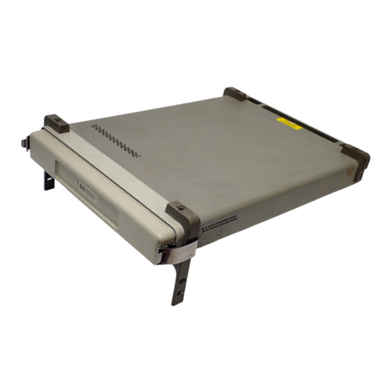
T D M A C E L L U L A R A D A P T E R ANALYZER UNLOCK RF IN/ RF IN/ DATA CLOCK IN Figure 76 HP 83206A Cellular Adapter Connectors Front and Back Views S:\HP83206A\USRGUIDE\MANUAL\connect.fm HP 83206A TDMA Cellular Adapter ANALYZER ANALYZER GENERATOR... -
Page 245: Front Panel Connectors
Analyzer Baseband Direct Input to the Digital Analyzer for analyzing data streams. This input is Data In available through HP-IB control of the TDMA Encoder screen. (Not in use at this time) Operating Considerations The rising edge of the Analyzer Data Clock In signal triggers the analyzer to read this data. - Page 246 Front Panel Connectors Analyzer Trigger In This connector allows external signals to trigger the Digital Analyzer to begin sampling the selected input. (Not in use at this time) Operating Considerations Used for frame synchronization of the analyzer. Input impedance = 100 k Input level = TTL (rising edge) Generator This connector allows you to send external data to the Pre-modulation filter/IQ...
-
Page 247: Connector Descriptions Rear Panel Connectors
Rear Panel Connectors Anl Trig Out This connector outputs the signal used to synchronize external equipment to the Digital Analyzer. A rising edge indicates the Analyzer was triggered. (Not in use at this time) Operating Considerations All values are rounded to the nearest full bit. Bit Clk Out This signal outputs a square wave from the Digital Generator’s Bit Clock. - Page 248 Set’s internal IBASIC computer to locate the faulty module. Ext IF In This port is generally connected to the HP 8920B Option 006 DET OUT port for making the average power measurement. This connector allows an external IF signal to be used in place of the 114.3 MHz IF that comes from the Test Set.
- Page 249 Frame Clk Out This connector provides a square wave from the Digital Generator’s Frame Clock. This allows you to synchronize external equipment to the Digital Generator. Operating Considerations Nominal output frequency = 25 Hz Output level = CMOS Output impedance = 50 Ohms Gen BB Data Out This connector monitors the digital signal applied to the Pre-modulation Filter/IQ Modulator.
-
Page 250: Serial Port
Rear Panel Connectors NOTE: Using a Frame or 2X Frame Reference: it takes about 30 seconds to lock to a 25 or 50 Hz reference after connecting the reference signal and selecting the correct setting in the Reference field. The 200 and 400 Hz selections are a little faster. If the reference signal is disconnected and then reconnected, you must re-select the reference frequency in the Reference field to start the phase-locking process over again. - Page 251 Chapter 8, Connector Descriptions Rear Panel Connectors 10 MHz REF OUT This rear-panel port outputs a 10 MHz reference. This signal is phase locked to the signal applied to the REF IN port. All clocks (Bit, Symbol, and Frame) are derived from or phase locked to this signal.
- Page 252 Rear Panel Connectors IQ RF OUT This rear-panel port outputs the carrier applied to the rear-panel CW RF IN connector. This port is normally connected to the Test Set’s rear-panel IQ RF IN connector. Operating Considerations Even when the Digital Generator is not actively sending a message, the IQ Modulator still receives symbol data.
-
Page 253: Troubleshooting
Troubleshooting This section discusses the probable causes of some problems that may occur while using the HP 83206A in your Test System. Sections are divided into groups dealing with specify hardware configurations and operating modes. Call for HP If, after using the information in this section, you still cannot solve your problem,... - Page 254 Test Set again. If you encounter this type of message, you should record the information listed below before turning the Test Set off, and then call your HP Field Engineer. You may also call the HP Support line at 1-800-922-8920.
- Page 255 Cellular Adapter is removed and reinstalled. “Power Measurements” on page 130 Power” on page 287. To Access the DCCH Call Processing Screens via HP-IB Use the same command to access the CALL CONTROL screen that you would use for AMPS operation: DISP ACNT command.
- Page 256 VSELP and ACELP vocoders in mobiles. If you have a Test Set with a firmware revision in the range of B.04.01 to B.05.00, you can only access the ACELP selection using remote (HP-IB) operation ( firmware version B.05.01 and above, you can select both vocoders manually or via HP-IB.
- Page 257 Remote Operation Considerations and Recommendations The following items discuss operation under HP-IB control. For much more information on programming in the Call Processing Subsystem, refer to the HP 8920B Programmer’s Guide HP P/N 08920-90222. Loopback BER When making loopback BER measurements on the DIGITAL MEASUREMENTS screen, configure the DTC settings on the CALL CONTROL screen prior to switching to the DIGITAL MEASUREMENTS screen.
-
Page 258: Control Screen
Refer to the HP 8920B Programmer’s Guide for more information on using the Call Processing Status Registers. - Page 259 Problems With or Without a PCS Interface Present This section deals with Test Systems that do not include a PCS Interface. Mobile will not Verify that you have correctly connected the mobile to the Test System. See “Connecting a Mobile” on page 38 camp on a Control Verify that you have set the System Type field (on the CALL CONTROL screen) to Channel.
- Page 260 Problems With or Without a PCS Interface Present The message The DIGITAL MEASUREMENTS screen expects to see a symbol clock to be “Symbol clock is able to make measurements on a DTC. This message occurs when accessing this weak: accuracy is screen while the mobile is on an AVC;...
- Page 261 Interface’s Serial Port. CONFIGURE 2. Verify that the HP-IB/SER switch on the PCS Interface is set to the SER position. screen. 3. Turn the Test Set and the PCS Interface off. 4. Turn the PCS Interface on and wait until it beeps twice. The two beeps indicate that the PCS Interface is set to serial control.
- Page 262 Messages Messages The messages included below are those specific to the Cellular Adapter. For Test Set messages refer to the HP 8920 Series Test Set User’s Guide. Alert attempted while not in Maintenance or Connect state. Amb Lite Communication FAILED.
-
Page 263: Chapter 9, Troubleshooting Messages
Chapter 9, Troubleshooting Messages Page attempted while not in Active state. Registration attempted while not in Active state. The release acknowledgment was not received from mobile. Release attempted while not in Connect state. RF Power Loss indicates loss of Voice Channel. Signal weak: accuracy may be degraded. - Page 264 Chapter 9, Troubleshooting Messages S:\HP83206A\USRGUIDE\MANUAL\trblesht.fm...
- Page 265 TIA/EIA-136 Basics This chapter briefly describes the TIA/EIA-136 system, and its Digital Control Channel (DCCH).
-
Page 266: Multiple Access)
What is TIA/EIA-136? What is TIA/EIA-136? TIA/EIA-136 is a mobile communications system standard which extends the functions of the dual-mode system standard TIA/EIA-627. TIA/EIA-627 is also known as NADC/TDMA (North American Dual Mode Cellular/Time Division Multiple Access). NADC/TDMA is a dual mode, full duplex cellular communications system in which each voice channel can be defined by both a frequency and a time slot. - Page 267 Basic Features of These features apply to the TIA/EIA-136 system as specified in the TIA/EIA TIA/EIA-136 system standards. Frequency Range 1900 MHz hyperband recommended Frequency Range Channel spacing Time slots per channel Users per voice/traffic channel Modulation Data structure Speech coding Modulation data rate TIA/EIA standards RX/TX frequency spacing...
- Page 268 TIA/EIA-136 transceiver TIA/EIA-136 transceiver The Transceiver The block diagram for a typical TIA/EIA-136 transceiver (Figure 77 on page 270) Control Block is nearly the same as that of an TIA/EIA-627 TDMA transceiver. The primary difference between the two systems is in the control channel. All control channel operations occur in the Transceiver Control Block.
- Page 269 Chapter 10, TIA/EIA-136 Basics TIA/EIA-136 transceiver Table 6 Major Transactions Which Can Be Processed in Idle or Camping Modes Transactions that can be processed Transactions that can be processed during Idle on an ACC during Camping on a DCCH Origination Origination Respond to pages Respond to pages...
-
Page 270: Transceiver Block Diagram
TIA/EIA-136 transceiver TIA/EIA-136 Transceiver Block Diagram Reverse Compressor Speech Coder Reverse Transceiver Control Block Forward Channel Speech Decoder Decoder 2:1 Expander Forward Figure 77 a TIA/EIA-136 Dual Mode Transceiver S:\HP83206A\USRGUIDE\MANUAL\is136bas.fm Limiter Modulator Channel Nyquist DQPSK Encoder Filter Modulator Nyquist Demodulator Filter FM Detector Reverse... - Page 271 Basic Functions of the DCCH in TIA/EIA-136 The process of making a TIA/EIA-136 call is essentially the same as making a TIA/EIA-627 TDMA call. The primary difference comes in the control channel functions. The following sections describe the functions of the Digital Control Channel (DCCH) used in TIA/EIA-136.
- Page 272 Basic Functions of the DCCH in TIA/EIA-136 The basic steps in initialization are described below. DCCH DCCH Scanning and Locking Initialization Tasks When checking control channels for the strongest one, a mobile may scan all channels. However, in the TIA/EIA-136 system, the DCCHs are scanned in blocks.
- Page 273 Determine Signal Strength Aspects: The mobile must evaluate the candidate DCCH for the following conditions: • received signal strength is sufficient • the maximum power of the mobile meets the system’s allowed maximum power criteria Determine Service Aspects: The mobile must evaluate the candidate DCCH for the following conditions: •...
- Page 274 Basic Functions of the DCCH in TIA/EIA-136 Table 7 Call Origination Steps 1 Begin In Camping or 1 Originate on Idle State 2 Create and Origination message contains SCM and Send Origination Message 3 Receive Receive DTC Channel designation Designation 4 Invoke Invoke Registration...
- Page 275 Basic Functions of the DCCH in TIA/EIA-136 Camping Mode This is the mode in which the mobile waits for orders, or originates a call. This is analogous to Idle mode in an analog system. Origination Message The mobile transmits an Origination Message after confirming that the channel is accessible by monitoring the Overload control.The Origination Message is transmitted on the RACH (Random Access Channel).
-
Page 276: Call Release
Basic Functions of the DCCH in TIA/EIA-136 Call Release During conversation mode, either party can terminate the call. On a mobile, this can be done by either pressing ‘END’ or by merely turning power off. When the mobile user terminates the call, the base station smoothly disconnects from the mobile. - Page 277 Basic Functions of the DCCH in TIA/EIA-136 Registration for TIA/EIA-136 differs under certain conditions. In these conditions, the mobile replies with a registration that contains a message specific to the condition. Some of the conditions are listed below. • If the mobile has just powered down, the registration will contain a message with a power down indication.
- Page 278 Basic Functions of the DCCH in TIA/EIA-136 REGID_PER: the number of superframes over which REGID is incremented. Ranges from 0 to 15 superframes. The value 0 indicates that REGID is not incremented. A superframe is 16 TDMA frames = about 640 milliseconds. Paging Paging occurs primarily for the base to establish a call with the mobile.
- Page 279 Handoffs and There are several types of handoffs possible within TIA/EIA-136. These are listed Mobile Assisted below. Handoff (MAHO) • DTC to DTC • DTC to AVC • AVC to DTC • AVC to AVC Basic steps in all handoffs 1.
-
Page 280: Short Message Service (Sms)
Basic Functions of the DCCH in TIA/EIA-136 Mobile Assisted Handoff (MAHO) MAHO is actually a set of measurements, not a handoff. The base station requires the mobile to provide RF channel signal quality information to its serving base station. The base can then choose a specific channel for the handoff. If the mobile provides information on the present RF channel, it sends RSSI and BER information. - Page 281 Authentication Authentication is the same for both the ACC and the DCCH. It consists of the base and mobile stations exchanging data. Before the mobile may access the system, this data is verified. Unique Challenge-Response Procedure This is the basic procedure of Authentication. The procedure is described below. 1.
- Page 282 Basic Functions of the DCCH in TIA/EIA-136 The procedure to update the SSD is listed below. 1. Base sends an SSD Update order containing the RANDSSD. 2. Mobile calculates a value SSD-A_NEW using RANDSSD, ESN, and the A-key. 3. Mobile generates a random number RANDBS and sends it to the base. 4.
- Page 283 Mobile Assisted The mobile can assist the base in selecting control channels by the MACA Channel procedure. This procedure measures and reports signal quality for either the Allocation(MACA) current channel or multiple channels. There are two types of measurements: long term and short term.
- Page 284 Chapter 10, TIA/EIA-136 Basics Basic Functions of the DCCH in TIA/EIA-136 S:\HP83206A\USRGUIDE\MANUAL\is136bas.fm...
- Page 285 Installing the Cellular Adapter This chapter shows how the Cellular Adapter is connected to the HP 8920 Test Set. Connections for the PCS Interface are also provided.
- Page 286 Connecting the Cellular Adapter to the HP 8920 Series Test Set Connecting the Cellular Adapter to the HP 8920 Series Test Set This preliminary Test Set Cellular Adapter will work only with an HP 8920B series Test Set with correct firmware. If you received firmware to upgrade your Test Set, follow the instructions included with the firmware.
-
Page 287: Chapter 11, Installing The Cellular Adapter Connecting The Cellular Adapter To The Hp 8920 Series Test Set
Connecting the Cellular Adapter to the HP 8920 Series Test Set I/Q Modulator and The I/Q Modulator and TX Power calibration routines must be run any time a Relative TX Power Cellular Adapter is disconnected and re-attached to a Test Set. TX Power should... - Page 288 To ANT IN To DUPLEX OUT Figure 79 PCS Interface Connections S:\HP83206A\USRGUIDE\MANUAL\adptinst.fm 10 MHz REF OUTPUT REF IN Serial Port Connections A0 (LSB) A5 (MSB) HP-IB/Ser The HP-IB/Ser switch must be set to Ser. Figure 78 on REF IN BNC Tee...
- Page 289 RJ-11 cable that provides separate RJ-11 jacks for each port. RJ11 08921-61031 Port 9 Port 10 RJ11 08921-61038 Chapter 11, Installing the Cellular Adapter PCS Interface Connections HP 8920 Rear Panel 83236--61061 Serial Printer Com 1 DB9 Serial Connector Serial Port...
- Page 290 Chapter 11, Installing the Cellular Adapter PCS Interface Connections S:\HP83206A\USRGUIDE\MANUAL\adptinst.fm...
- Page 291 Glossary ACC Analog Control Channel. Controls the analog transmissions of a cellular phone system. Access The Test Set’s state in which the it is communicating with the transceiver under test. acknowledgment The process by which one station sends a response message to another station.
- Page 292 Glossary autonomous registration The process by which the mobile registers without being instructed to do so by the base. AVC Analog Voice Channel average power The RMS power. base station A station in the Domestic Public Cellular Radio Telecommunications Service, other than a mobile station, used for communicating with the mobile.
- Page 293 Glossary DIG MEAS The screen for digital measurements primarily in the TIA test mode. digital call processing the portion of the Test Set which control the messages required to setup and maintain a call in the digital portion of a cellular phone system. Disarm Selecting this command stops the measurement process.
- Page 294 Firmware located in the Test Set (the host). HP-IB See GPIB. Idle The state on an ACC in which the mobile is available to originate a call or accept orders. Analogous to Camping on a DCCH.
- Page 295 Glossary notch filter A filter with a notch characteristic. A certain band (usually narrow) of frequencies is rejected, usually with high suppression. order A message sent from the base to the mobile which instructs the mobile to perform an action. origin offset The magnitude of the RF carrier leakage relative to the magnitude of the modulated carrier at the detection point.
- Page 296 Glossary RACH Random Access Channel. RAND Random challenge memory. A value stored in the mobile. Used in authentication. RDTC Reverse Digital Traffic Channel. REGID The system clock used for periodic registration. Register The Test Set’s state in which registration occurs. registration The process by which a mobile identifies itself to a base.
- Page 297 Glossary subsystem A section of firmware grouped together for a specific task. sync location The time in number of bit periods from the trigger to the beginning of the first sync word detected. TDMA Time Division Multiple Access. A type of frequency division in which one frequency is shared by multiple activities sequentially.
- Page 298 Glossary wake up The process of the mobile returning to its fully active state, after being in sleep mode, WER Word Error Rate.The number of erroneous words received compared to the total number of words received during the observation period. zero (power meter) The process by which the Test set measures loss through the Test Set in order to provide the most accurate...
- Page 299 Symbols Numerics # Neighbors field 1 of N field DCCH Call Configure screen, # Systems field 10 MHz REF OUT, DCCH Call Configure screen, 10MHz reference, % BIT ERROR field 1900 MHz testing, DCCH Call Configure screen, 2x Frame triggering, 750 us de-emphasis, A_KEY field Authentication screen (AVC),...
- Page 300 Autotuning with PCS, definition, AVC authentication, AVC channel type, AVC connection ends, average power definition, measuring, Average Power measurements, Avg Power zero, HP-IB operation, BAND field (Neighbor List) DCCH Call Configure screen, base station active mode, definition, emulating, personal, definition,...
-
Page 301: Voice Channel Assignment
calibration (temperature compensation), call processing Calibration factors restoring, call originated by mobile, CALL CNFG definition, CALL CNTL definition, CALL CONFIGURE screen, Call Configure screen Calling Num, caller ID call connected indicator, CALL CONTROL screen, how to access, Call Control screen Access annunciator, Active annunciator, Active field,... - Page 302 SMS Contents field, SMS Msg field, SMS Size field, SMS Type field, SOC field, view of, DCCH DVCC field DCCH Call Configure screen, DCCH screens via HP-IB, DCCH subsystem definition, DCCH system type, DCCH WER measuring, DCFM Offset calibrating, De-Emphasis field...
- Page 303 DTMF, definition, EIA/TIA-136, 32, dual tone multi-frequency signaling, dual tone multiple frequency definition, definition, DVCC choosing the correct, 85, 90, EIA/TIA-136 CALL CONTROL screen for the DCCH, DVCC field EIA/TIA-136 transceiver Call Control screen, Digital Measurement screen, EIA/TIA-627, DVCC. electronic serial number (ESN), 237, See digital verification color code emulate error vector magnitude...
- Page 304 HP 83206A about, call processing tasks, HP 8920 using the Test Set, HP Support phone number, HP-IB accessing DCCH screens, displaying screens, HP-IB command syntax Integer Number Setting, Multiple Real Number Setting, Real Number Setting,...
- Page 305 124, MSID procedure, definition, setting up the measurement, MSID field Call Control screen, Multiple Real Number Setting definition, HP-IB command syntax diagram, MWI, sending, definition, changing the display, AF frequency, changing units, current, dc level, distortion, no call processing during Meas mode,...
- Page 306 Name Size field DCCH Call Configure II screen, neighbor channels, neighbor list definition, Neighbor List BAND field DCCH Call Configure screen, Neighbor List Channel field DCCH Call Configure screen, neighbors, number of, no reverse DTC detected, non-public system definition, non-public system selection, Non-recoverable firmware error, Not Avail, Not Scrn (not screened) screening,...
- Page 307 Phone number HP Support, phone number MS Id, picocell definition, programming power gain, power level, Power Measurements, programming commands Power Meter field DCCH Call Configure screen, power on and initialization, Pres OK, Pres Res, Pres Type field...
- Page 308 Authentication screen (AVC), RANDSSD_2 field Authentication screen (AVC), RANDSSD_3 field Authentication screen (AVC), RDTC definition, Real Number Setting HP-IB command syntax diagram, received signal strength indication definition, REF UNLOCK indicator, reference unlocked, Reg Conf field DCCH Call Configure screen, REG_PER...
- Page 309 System Type field Call Control screen, TDMA, definition, temperature compensation, 47, Temperature compensation, over HP-IB, Temperature field DCCH Call Configure II screen, test mode, definition, Test Set connecting to Cellular Adapter, test set...
- Page 310 TX frequency error definition, TX power definition, measuring, TX Power measurement Analog Meas screen, TX Power measurements, TX Power Zero, Type field Call Control screen, units changing, user group definition, Index VC Order field Call Control screen, vector sum excited linear predictive definition, Ver&Fail (verify and fail) screening, Ver&Pass (verify and pass) screening,...
- Page 311 wake up zero power meter definition, zero the Average Power meter, definition, zero the RF Power meter measuring, word error rate Zeroing the Average Power Meter, definition, definition, how often, Index...
- Page 312 Index...
Need help?
Do you have a question about the HP 83206A and is the answer not in the manual?
Questions and answers