Table of Contents
Advertisement
Advertisement
Table of Contents

Related Manuals for Henny Penny PFE-591


Summary of Contents for Henny Penny PFE-591
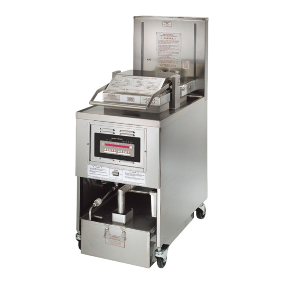
- Page 1 Henny Penny Pressure Fryer-Electric Model PFE-591 OPERATOR’S MANUAL...
- Page 3 0 TO 3 YEARS: During this time, any frypot that fails due to manufacturing or workmanship is- sues will be replaced at no charge for parts, labor, or freight. Henny Penny will either install a new frypot at no cost or provide a new or reconditioned replacement fryer at no cost.
- Page 4 HENNY PENNY 8 HEAD ELECTRIC PRESSURE FRYER SPECIFICATIONS Height 61" (155 cm) Width 24" (61 cm) Depth 41¾" ( 107 cm) Floor Space Approximately 7 sq. ft. (.65 sq. m.) Pot Capacity 8 head of chicken - 21 lbs. (9.5 kg) 100 lbs.
-
Page 5: Table Of Contents
TABLE OF CONTENTS Section Page Section 1. INTRODUCTION ....................1-1 Pressure Fryer ....................1-1 Proper Care ....................1-1 Assistance ..................... 1-1 Safety ......................1-2 Section 2. INSTALLATION ...................... 2-1 Introduction ....................2-1 Unpacking ..................... 2-1 Selecting the Fryer Location ................. 2-5 Leveling the Fryer .................. -
Page 6: Section 1. Introduction
Model PFE- 591 SECTION 1. INTRODUCTION 1-1. PRESSURE FRYER The Henny Penny pressure fryer is a basic unit of food processing equipment. It has found wide application in institutional and com- mercial food service operations. P-H-T A combination of pressure, heat, and time is automatically controlled to produce the optimum in a tasty, appealing product. -
Page 7: Safety
Model PFE- 591 1-4. SAFETY The Henny Penny pressure fryer has may safety features incorporated. However, the only way to ensure a safe operation is to fully understand the proper installation, operation, and maintenance procedures. The instructions in this manual have been prepared to aid you in learning the proper procedures. -
Page 8: Section 2. Installation
SECTION 2. INSTALLATION 2-1. INTRODUCTION This section provides the installation and unpacking instructions for the Henny Penny Model PFE-591. Installation of this unit should be performed only by a qualified service technician. Do not puncture the fryer with any objects such as drills or screws as electrical shock or component damage could result. - Page 9 Model PFE- 591 2-2. UNPACKING Remove the counterweights from the pallet, which are INSTRUCTIONS strapped to the pallet, under the fryer. (Continued) Do not drop. The counterweights weigh approximately 18 lbs. (8.1 kg.) each. Handle with care, or personal injury could result. Remove rear cover.
- Page 10 Model PFE- 591 Optional Ramp Unloading...
- Page 11 Model PFE- 591...
-
Page 12: Selecting The Fryer Location
Model PFE- 591 2-3. SELECTING THE FRYER The proper location of the fryer is very important for operation, LOCATION speed, and convenience. Choose a location which will provide easy loading and unloading without interfering with the final assem- bly of food orders. Operators have found that frying from raw to finish, and holding the product in a warmer provides fast continuous service. -
Page 13: Ventilation Of Fryer
Model PFE- 591 2-5. VENTILATION OF FRYER The fryer should be located with provision for venting into adequate exhaust hood or ventilation system. This is essential to permit efficient removal of steam exhaust and frying odors. Special precaution must be taken in designing an exhaust canopy to avoid interference with the operation of the fryer. -
Page 14: International Electrical Requirements
Model PFE- 591 2-7. INTERNATIONAL Units being used outside the United States may not be shipped ELECTRICAL with the power cord attached to the unit because of the different REQUIREMENTS wiring codes. The fryers are available from the factory wired for 208, 240, 380 and 415 volts, 3 phase, 50 Hertz service. - Page 15 BE CERTAIN THAT THE GAS CONTROL VALVE AND BURNERS ARE PROPERLY ADJUSTED. (GAS UNITS ONLY) • USE RECOMMENDED LOAD SIZE FOR ADDITIONAL INFORMATION ON THESE INSTRUCTIONS, REFER TO THE HENNY PENNY OPERATOR MANUAL AND THE KFC STANDARDS LIBRARY. FOR ASSISTANCE CALL THE HENNY PENNY SERVICE DEPARTMENT AT 1-800-417-8405. 1-937-456-8405...
-
Page 17: Section 3. Operation
Model PFE- 591 SECTION 3. OPERATION 3-1. OPERATING COMPONENTS Frypot This reservoir holds the cooking shortening, and is designed to accommodate the heating elements, 8 head of product and an adequate cold zone for collection of cracklings Carrier This stainless steel carrier consists of five racks, containing the food product during and after frying Lid Gasket Provides the pressure seal for the frypot chamber... - Page 18 Model PFE- 591 3-1. OPERATING COMPONENTS (Continued) Pressure Gauge Indicates the pressure inside the frypot Solenoid Valve An electromechanical device that causes pressure to be held in the frypot The valve closes at the beginning of the Cook Cycle and opens automatically at the end of the Cook Cycle;...
- Page 19 Model PFE- 591 3-1. OPERATING COMPONENTS (Continued) High Temperature Limit This is a safety component that senses the temperature of the shortening; if the temperature of the shortening exceeds 420°F (212°C), this control opens and shuts off the heat to the frypot; when the temperature of the shortening drops to a safe operation limit, the control must be manually reset by pressing the red reset button, located under the control panel, in the right, front of the fryer...
-
Page 20: Lid Operation
Model PFE- 591 To close lid: 3-2. LID OPERATION 1. Lower the lid until lid latches into place. 2. Pull lid handle forward until it stops. 3. Lift up on the lid handle until it stops. 4. Bring lid handle out towards you until it stops. 5. - Page 21 Model PFE- 591 3-2. LID OPERATION (Continued) To open lid: DO NOT LIFT HANDLE OR FORCE LID LATCH OPEN BEFORE PRESSURE GAUGE READS “0” PSI. ESCAPING STEAM AND SHORTENING WILL RESULT IN SEVERE BURNS. 1. Gently raise handle until it stops. 2.
-
Page 22: Switches And Indicators
Model PFE- 591 3-3. SWITCHES AND Refer to image at end of this section. INDICATORS Fig. Item Description Function Lights when the control calls for heat; the elements come on and heats the shortening. Digital Display Shows all the functions of the Cooking Cycle, Program Modes, Diagnostic Modes, and alarms Lights when the solenoid closes and pressure starts to build inside frypot... - Page 23 Model PFE- 591 3-3. SWITCHES AND INDICATORS (Continued) Fig. Item Description Function Press to access Program Modes; once in the Program Mode, it is used to advance to the next setting; if pressed along with it accesses the Information Mode which has historic information on the operator and fryer’s performance Used to start and stop Cook Cycles, and to stop the timer at the end of a Holding Cycle...
- Page 24 Model PFE- 591 Figure 3-1...
-
Page 25: Clock Set
Model PFE- 591 3-4. CLOCK SET Upon initial start-up, or PC board replacement, if “CLOCK SET” automatically appears in the display, start with step 4. Press and hold for 5 seconds until “LEVEL 2” shows in display. Press and “CLOCK SET”, “ENTER CODE” shows in display. - Page 26 Model PFE- 591 3-4. CLOCK SET 14. Press and “CS-6, CLOCK MODE” shows in the (Continued) display, along with “1.AM/PM”. “1.AM/PM” is 12 hour time, “2.24-HR” is 24 hour time. Press to change. 15. Press and “CS-7, DAYLIGHT SAVINGS ADJ” shows in the display, along with “2.US”.
-
Page 27: Filling Or Adding Shortening
Model PFE- 591 3-5. FILLING OR ADDING SHORTENING The shortening level must always be above the heating elements when the fryer is heating and at the frypot level indicators on the rear of the frypot (Figure 3-3). Failure to follow these instructions could result in a fire and/or damage to the fryer. -
Page 28: Product Racking Recommendations
Model PFE- 591 3-6. PRODUCT RACKING RECOMMENDATIONS The rack positions are referenced starting at the bottom: 4 _____________ 3 _____________ 2 _____________ 1 _____________ The bottom position is to be avoided on small loads because it is closer to the cold zone. (The oil is cooler at the bottom of the frypot and hotter at the top.) With bigger loads, however, there is generally enough turbulence in the oil that the bottom rack gets sufficient heat. -
Page 29: Basic Operation
Model PFE- 591 3-7. BASIC OPERATION Follow the procedures below on the initial start-up of the fryer, and each time the fryer is brought from a cold, or shut down condition. Make sure the frypot is filled with shortening to the lower level indicator. - Page 30 Model PFE- 591 3-7. BASIC OPERATION Allow fryer to heat until illuminates. (Continued) Bypass Melt Cycle, if desired, by pressing a product button and holding it for five seconds. The display shows “EXIT MELT? 1=YES 2=NO”. Press to exit melt. Do not bypass the Melt Cycle unless enough shortening has melted to completely cover all of the heating elements.
- Page 31 Model PFE- 591 3-7. BASIC OPERATION Wait for the pressure gauge to show “0” pressure in the (Continued) pot before attempting to open the lid. DO NOT LIFT HANDLE OR FORCE LID LATCH OPEN BEFORE PRESSURE GAUGE READS “0” PSI. ESCAPING STEAM AND SHORTENING WILL RESULT IN SEVERE BURNS.
-
Page 32: Care Of Shortening
Model PFE- 591 3-7. BASIC OPERATION Once filtering is complete and the COOK/PUMP switch is (Continued) turned back on, “IS POT FILLED” shows in the display, followed by “1=YES 2=NO”. If shortening is at the proper level in the frypot, press the controls start a normal heating process. -
Page 33: Filtering Instructions
PERSONAL INJURY, FIRE, AND/OR PROPERTY DAMAGE COULD RESULT. 3-9. FILTERING The Henny Penny Electric 8 Head Fryer, Model PFE-591, must be INSTRUCTIONS cleaned and the shortening filtered at least twice daily; after lunch rush and at the end of the day. - Page 34 Model PFE- 591 3-9. FILTERING High volume cooking could cause the cold zone to fill quicker with INSTRUCTIONS cracklings and cleaning may be required more often. Part of the (Continued) process involves removing cracklings from the cold zone of the frypot.
- Page 35 Model PFE- 591 3-9. FILTERING INSTRUCTIONS When all of the shortening has drained, scrape or brush the (Continued) sides and bottom of the frypot, and swing drain valve handle to the closed position. Do not bang the pot scraper, or other cleaning utensil, on the frypot rim.
-
Page 36: Changing The Filter Envelope
Model PFE- 591 3-9. FILTERING INSTRUCTIONS Turn COOK/PUMP switch to PUMP. (Continued) When all shortening has been pumped into frypot turn COOK/PUMP switch off. IF THERE ARE AIR BUBBLES COMING UP IN THE SHORTENING, IT’S POSSIBLE THAT THE FILTER CONNECTION AT THE UNION ON THE FILTER TUBE IS NOT TIGHTENED PROPERLY. - Page 37 Model PFE- 591 3-10. CHANGING THE FILTER Remove the filter clips and discard the filter envelope. ENVELOPE (Continued) Clean the top and bottom filter screen with soap and water. Rinse thoroughly with hot water. Be sure that the filter screens, crumb catcher, filter clips, and the standpipe are thoroughly dry before assembly of filter envelope as water will dissolve the filter paper.
-
Page 38: Filter Pump Motor Protector-Manual Reset
Raise lid, remove the racks and carrier from lid, and tilt lid back, so that the lid won’t interfere with cleaning. Henny Penny has the following cleaners available: Foaming Degreaser - Part no. 12226 PHT Liquid Cleaner - Part no. 12135 PHT Dry Powder Cleaner - Part no. - Page 39 3-12. CLEANING THE FRYPOT Fill the frypot to the level indicators with hot water. (Continued) Add 8 to 10 ounces of fryer cleaner (Henny Penny part number 12101) to the water and mix thoroughly. Always wear chemical splash goggles or face shield and protective rubber gloves when cleaning the frypot as the cleaning solution is highly alkaline.
- Page 40 Using the fryer brush (Henny Penny part number 12105) scrub the inside of the frypot, the lid frame, and around the counter-top of the fryer.
-
Page 41: Regular Maintenance
Model PFE- 591 3-13. REGULAR MAINTENANCE As in all food service equipment, the Henny Penny pressure fryer does require care and proper maintenance. The table below provides a summary of scheduled maintenance. The following paragraphs provide step-by-step maintenance procedures to be performed by the operator. - Page 42 Model PFE- 591 3-14. PREVENTIVE Cleaning Deadweight Assembly - Daily MAINTENANCE (Continued) DO NOT ATTEMPT TO REMOVE DEADWEIGHT CAP WHILE FRYER IS OPERATING. SEVERE BURNS OR OTHER INJURIES WILL RESULT. At the end of each day’s usage of the fryer, the deadweight assembly must be cleaned.
- Page 43 Model PFE- 591 3-14. PREVENTIVE Reversing Lid Gasket - Every 90 Days MAINTENANCE Continued) Reversing the lid gasket helps to prevent early failure of lid gasket and the loss of pressure during a cook cycle. Raise the lid and remove racks and carrier. Grasping the lid handle, lift the front of the lid up until it stops in an upright position.
- Page 44 Model PFE- 591 3-14. PREVENTIVE Cleaning Safety Relief Valve-Annually MAINTENANCE Continued) SAFETY VALVE DO NOT ATTEMPT TO REMOVE SAFETY VALVE WHILE FRYER IS OPERATING, OR SEVERE BURNS OR OTHER INJURIES WILL RESULT. 1. Use a wrench to remove pressure gauge. 2.
-
Page 45: Programming
Model PFE- 591 3-15. PROGRAMMING Press and hold for one second until “PROG” shows in the display, followed by “ENTER CODE”. Enter code 1, 2, 3. “SELECT PRODUCT…PRESS PROG” scrolls across the display. Press and release the desired product button (1 to 10). If no buttons are pressed within approximately 2 minutes while in the Program Mode, the controls will revert back to the Cook Mode. - Page 46 Model PFE- 591 Press and release and “1. COOK TIME” shows in 3-15. PROGRAMMING (continued) the display along with the preset time. Press to change the time. The time shows in minutes and seconds. Press and hold the buttons, and the time will jump by 5 second increments to a maximum of 59:59.
- Page 47 Model PFE- 591 3-15. PROGRAMMING After the alarm time is set, press and “ALARM” and (continued) “TYPE” flashes in the display, with the alarm type on the right side of the display. “TIME”, “SHAKE”, “STIR”, “ADD”, and “LID” can be set by pressing .
- Page 48 Model PFE- 591 3-15. PROGRAMMING Or, to use the cooking setpoint temperature as the load (Continued) compensation reference point, press until “STEP-X” and “TEMP” flashes in the display. Now for example, if the cooking temperature is 350°, the timer speeds up when the shortening temperature is above 350, and slows down when the temperature is below 350.
- Page 49 Model PFE- 591 3-15. PROGRAMMING Copy/Erase Pre-set Products (Continued) Products and their setpoints can be copied from one menu location on the controller to another location, preset the controls to factory settings, or erase products and all their values. Press and hold for one second until “PROG”...
- Page 50 Model PFE- 591 3-15. PROGRAMMING (Continued) Next, press product you want to copy to, for example, by pressing . The controller responds with a confirmation message: “COPY 2 TO 0?” “1=YES 2=NO” Press (YES) and the controller copies product #2 to the product #0 position (the #2 product is left intact) and the display shows “* COPIED *”, then returns to the “Select Prog Product”...
-
Page 51: Special Program Mode
Model PFE- 591 3-16. SPECIAL PROGRAM The Special Program Mode is used to set more detailed MODE parameters listed below. SP-1 · Degrees Fahrenheit or Celsius SP-2 · Language: English, French, German, Spanish, and Portuguese SP-3 · System initialization SP-4 ·... - Page 52 Model PFE- 591 3-16. SPECIAL PROGRAM Language (SP-2) MODE (Continued) a. Follow steps 1 and 2 above. b. Press and release button. “SP-2” and “LANGUAGE” flashes on the display, along with the language (Ex:” 1.ENGL”) c. To toggle to the desired language, press and release System Initialization (SP-3) This step resets the controls, but doesn’t erase product settings.
- Page 53 Model PFE- 591 3-16. SPECIAL PROGRAM Type of shortening to be melted - Liquid or Solid (SP-6) MODE (Continued) The Melt Cycle can be set to the type of shortening being used. a. Follow steps 1 and 2 above. b. Press and release 5 times.
- Page 54 Model PFE- 591 3-16. SPECIAL PROGRAM e. Change the idle setpoint temperature, by pressing MODE (Continued) f. Press and release . “SP-7B” and “AUTO-IDLE MINUTES” shows in the display, along with the preset time. g. Press to set the minutes the fryer stays idle before the Auto-idle is enabled;...
- Page 55 Model PFE- 591 3-16. SPECIAL PROGRAM f. Press and “SP-8C” shows in the display, if YES MODE (Continued) was chosen in step e. “FILTER LOCKOUT AT…” and a value between 100% and 200% shows in display. Press to change this value. g.
- Page 56 Model PFE- 591 3-16. SPECIAL PROGRAM SCHEDULE MODE (Continued) m. If “4,SCHED” is selected, “SP-8A” shows in the display, and followed by “SCHEDULE”. Press the and up to 4 different times of day can be programmed, by pressing SP-8A “SCHEDULE” F1: 10.00A SP-8B “SCHEDULE”...
- Page 57 Model PFE- 591 3-16. SPECIAL PROGRAM Product Buttons (Sp-9) MODE (Continued) This mode allows you set up the way products are selected, and Cook Cycles started, in the cook mode. a. Follow steps 1 and 2 above. b.Press and release until “SP-9”...
- Page 58 Model PFE- 591 3-16. SPECIAL PROGRAM Manager Code Change (SP-15) MODE (Continued) This allows the operator to change the program code, or manager code (factory set at 1, 2, 3) used to access Product Programming, Special Programming, Clock Set, Data Comm, and Heat Control Modes.
-
Page 59: Data Logging, Heat Control, Tech And Stat Modes
Model PFE- 591 3-16. SPECIAL PROGRAM Change Shortening Cook Cycles (SP-17) MODE (Continued) This mode allows the operator to set the number of Cook Cycles between shortening changes. When the set numbers of Cook Cycles is reached, the control displays “CHANGE OIL”. This mode is just a reminder and cooking can continue. -
Page 60: Information Mode
Model PFE- 591 3-17. INFORMATION MODE This mode gathers and stores historic information on the fryer and operator’s performance. Press at the same time and “*INFO MODE*” shows on display. Press to access the steps and press to view the statistics within each step. - Page 61 Model PFE- 591 3-17. INFORMATION MODE 2. LAST LOAD (Continued) Press to view the following information from the most recent Cook Cycle. FUNCTION DISPLAY EX: Time of day the last cook cycle was started STARTED 10.25A Product (Last product cooked) PRODUCT Ready? (Was fryer Ready before start?) READY?
- Page 62 Model PFE- 591 3-17. INFORMATION MODE 4. REVIEW USAGE (Continued) Press to view the accumulated information since the data was manually reset: FUNCTION DISPLAY EX: Day the usage data was previously reset SINCE APR-19 Number of hours the fryer was on PWR ON HRS Number of times oil was filtered FILTERED...
- Page 63 Model PFE- 591 3-17. INFORMATION MODE Press to view the specific status of each input. An (Continued) underscore (“_”) indicates the input is not presently detected. A checkmark (“ ”) indicates the signal is detecting a normal input. A blinking (“X”) indicates the signal is presently detected, but is detected as a half-wave (partially failed) input.
- Page 64 Model PFE- 591 3-17. INFORMATION MODE Press and “6. PMP_ AIR_” shows in display. (Continued) Press to view the amp “DRAW” status of the pump motor output and air valve output. “PMP ” and “AIR ” in the display means the amps are good. A flashing “X” behind the “PMP”...
- Page 66 Model PFE- 591 • Fryer plugged in Power switch on but fryer • Open circuit • Check breaker or fuse at wall completely inoperative • Turn off and allow fryer to cool to Pressure not exhausting at • Solenoid or exhaust line clogged release the pressure in frypot;...
- Page 67 Model PFE- 591...
- Page 68 Model PFE- 591...
-
Page 69: Glossary
Model PFE- 591 G L O S S A R Y HENNY PENNY PRESSURE FRYERS air valve a valve that allows air into the filter lines when the pump is on in the mixing mode on eight head fryers airflow switch a switch that senses the amount of airflow coming from the blower;... - Page 70 Model PFE- 591 counterweight assembly an assembly of weights and cables that enable the eight head fryer lid to lift easily cracklings the crumbs of breading that come off the product during a cook cyclecrumb catcher the part of the filter assembly on four head fryers that filters crumbs out of the shortening before the shortening is pumped back into the frypot crumb catcher the part of the filter assembly on four head fryers that filters crumbs out of the...
- Page 71 Model PFE- 591 filter drain pan a pan that rolls or slides under the fryer into which shortening is drained filter envelope a fiber envelope into which the filter screen is placed; the end of the envelope is folded and held closed with filter clips; a part of the filter screen assembly filter quick disconnect an optional connection on the fryers allowing the filter rinse hose to be con- nected or released without tools...
- Page 72 Model PFE- 591 lid assembly an assembly comprised of lid, lid handle, lid latch, and lid gasket (Note: on four head fryers. the lid assembly includes spindles) lid gasket the gasket around the lid that creates a seal when the lid is properly latched lid handle a handle that is attached to the lid and is used to lower the lid into contact with the frypot;...
- Page 73 Model PFE- 591 sift breading the process of removing clumps from breading solenoid valve a valve used to generate or release pressure for the cook cycle spark igniters the igniters that create a spark to ignite the pilot lights on eight head gas fryers (gas fryers only) (see ignition modules) standpipe...
Need help?
Do you have a question about the PFE-591 and is the answer not in the manual?
Questions and answers