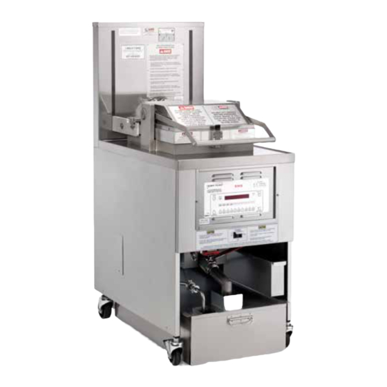
Henny Penny PFE-592 Operator's Manual
Pressure fryer (electric)
Hide thumbs
Also See for PFE-592:
- Technical manual (80 pages) ,
- Introduction (3 pages) ,
- Operator's manual (52 pages)

Related Manuals for Henny Penny PFE-592


Summary of Contents for Henny Penny PFE-592
- Page 1 PFE-590 PFE-592 R E G I S T E R W A R R A N T Y O N L I N E AT W W W. H E N N Y P E N N Y. C O M...
- Page 4 HENNY PENNY 8 HEAD ELECTRIC PRESSURE FRYER Fryer must be installed and used in such a way to prevent water from contacting the shortening. This appliance is not intended to be operated by means of an external timer or a separate remote control system.
- Page 5 HENNY PENNY – 8 HEAD ELECTRIC PRESSURE FRYER SPECIFICATIONS Height 61” (155 cm) Width 24” (61 cm) Depth 41¾” ( 107 cm) Floor Space Approximately 7 sq. ft. (.65 sq. m.) Pot Capacity 8 head of chicken - 22 lbs. (9.9 kg) 100 lbs.
-
Page 6: Table Of Contents
TABLE OF CONTENTS Section Page Section 1. INTRODUCTION ......................1 1-1. Pressure Fryer ..................... 1 1-2. Proper Care ......................1 1-3. Assistance ......................1 1-4. Safety ........................2 Section 2. INSTALLATION ......................5 2-1. Introduction ......................5 2-2. Unpacking......................5 2-3. -
Page 7: Section 1. Introduction
SECTION 1: INTRODUCTION The Henny Penny pressure fryer is a basic unit of food processing equipment which is used only in institutional and commercial food PRESSURE FRYER service operations. P-H-T A combination of pressure, heat, and time is automatically controlled to produce the optimum in a tasty, appealing product. -
Page 8: Safety
The Henny Penny pressure fryer has may safety features 1-4. incorporated. However, the only way to ensure a safe operation SAFETY is to fully understand the proper installation, operation, and maintenance procedures. The instructions in this manual have been prepared to aid you in learning the proper procedures. - Page 9 1-4. SAFETY (CONT.) Equipotential Ground Symbol Waste Electrical and Electronic Equipment (WEEE) Symbol Shock Hazard Symbols Hot Surface Symbols Sept. 2008...
- Page 10 July 2003...
-
Page 11: Section 2. Installation
SECTION 2: INSTALLATION This section provides the installation and unpacking instructions for the 2-1. Henny Penny PFE-590. INTRODUCTION • Installation of this unit should be performed only by a qualified service technician. Do not puncture the fryer with any objects such as drills or screws as electrical shock or component damage could result. - Page 12 2-2. Remove the counterweights from the pallet, which are strapped to the pallet, under the fryer. UNPACKING INSTRUCTIONS (CONT.) Do not drop. The counterweights weigh approximately 18 lbs. (8.1 kg.) each. Handle with care, or personal injury could result. Remove rear service cover. Load the seven weights into the counterweight assembly.
- Page 13 Optional Ramp Unloading Dec. 2016...
- Page 14 REMOVE 2 BOLTS MARKED “A” TO RELEASE FRAME AFTER INSTALLING WEIGHT SEGMENTS INSERT 6TH & 7TH SEGMENT INSERT 4TH & 5TH SEGMENT INSERT 2ND & 3RD SEGMENT INSERT 1ST SEGMENT EACH WEIGHT SEGMENT WEIGHS APPROXIMATELY 18 LBS. (8.1 KG) - HANDLE WITH CARE ALL SEGMENTS ARE IDENTICAL.
-
Page 15: Selecting The Fryer Location
The proper location of the fryer is very important for operation, speed, and convenience. Choose a location which will provide easy 2-3. loading and unloading without interfering with the final assembly SELECTING THE of food orders. Operators have found that frying from raw to finish, LOCATION and holding the product in a warmer provides fast continuous service. -
Page 16: Ventilation Of Fryer
The fryer should be located with provision for venting into adequate 2-5. exhaust hood or ventilation system. This is essential to permit efficient VENTILATION removal of steam exhaust and frying odors. Special precaution must OF FRYER be taken in designing an exhaust canopy to avoid interference with the operation of the fryer. -
Page 17: International Electrical Requirements
Units being used outside the United States may not be shipped with 2-7. the power cord attached to the unit because of the different wiring INTERNATIONAL codes. The fryers are available from the factory wired for 208, 240, 380 ELECTRICAL and 415 volts, 3 phase, 50 Hertz service. - Page 18 2-7. INTERNATIONAL • The supply power cords shall be oil-resistant, ELECTRICAL sheathed flexible cable, no lighter than ordinary REQUIREMENTS polychloroprene or other equivalent synthetic (CONT.) elastomer-sheathed cord. • It is recommended that a 30 mA rated protective device such as a residual current circuit breaker (RCCB), or ground fault circuit interrupter (GFCI), be used on the fryer circuit.
- Page 19 • BE CERTAIN THAT THE GAS CONTROL VALVE AND BURNERS ARE PROPERLY ADJUSTED. (GAS UNITS ONLY) • USE RECOMMENDED PRODUCT LOAD SIZE FOR ADDITIONAL INFORMATION ON THESE INSTRUCTIONS, REFER TO THE HENNY PENNY OPERATOR MANUAL AND THE KFC STANDARDS LIBRARY. FOR ASSISTANCE CALL THE HENNY PENNY SERVICE DEPARTMENT AT 1-800-417-8405.
- Page 20 July 2003...
-
Page 21: Section 3. Operation
SECTION 3: OPERATION OPERATING COMPONENTS A three way switch with center OFF position; move the switch to the POWER/PUMP Switch position marked POWER to operate the fryer; move the switch to the position marked PUMP to operate the filter pump; certain conditions must be met prior to operation of the filter pump;... - Page 22 An ASME approved spring loaded valve set at 14.5 psi (999 mbar); in the event the operation valve becomes obstructed, this safety valve 3-1. releases excess pressure, keeping the frypot chamber at 14.5 psi OPERATING COMPONENTS (999 mbar); if this occurs, turn the COOK/ PUMP switch to the OFF position to release all pressure from the frypot (CONT.) If safety relief valve activates, turn main power...
- Page 23 3-1. OPERATING COMPONENTS (CONT.) A microswitch that provides protection for the frypot in the event an Drain Interlock Switch operator inadvertently drains the shortening from the frypot while the main switch is in the COOK position; the switch is designed to automatically shut off the heat when the drain valve is opened The collection point for the condensation formed within the steam Condensation Drain Pan...
-
Page 24: Lid Operation
3-1. OPERATING COMPONENTS (CONT.) Filter Union Connects the filter to the filter pump, and allows easy removal of the filter and drain pan Fuses A protective device which breaks the circuit when the current exceeds the rated value To close lid: 3-2. -
Page 25: Melt Cycle Operation
3-2. LID OPERATION Lower the handle before attempting to raise the (CONT.) lid, or damage to the lid could result. 4. Push handle back. 5. Unlatch the front lid latch. If lid becomes difficult to operate, stop using the fryer and call for service. Cables need replaced. 3-3. -
Page 26: Controls And Indicators
Model 590/592 3-4. CONTROLS AND INDICATORS 10160009 Item Name Description SCAN Button Allows the operator to toggle through any running multiple timers. Temperature Button Allows the operator to read the temperature of the shortening while in a Cook Cycle. Digital Display Display shows cooking times along with any prompts or messages. -
Page 27: Display Messages
Model 590/592 3-5. DISPLAY MESSAGES There are messages shown on the digital display during operation. Some of the most common messages are described in the table below: Message Description The display reads “HI” if the shortening temperature is 40° F above the setpoint DROP The display reads “DROP”... -
Page 28: Filling Or Adding Shortening
3-6. FILLING OR ADDING SHORTENING The shortening level must always be above the heating elements when the fryer is heating and at the frypot level indicators on the rear of the frypot (Figure 3-3). Failure to follow these instructions could result in a fire and/or damage to the fryer. -
Page 29: Basic Operation
Follow the procedure below on the initial start-up of the fryer, and each time the fryer is brought from a cold, or shut down condition, back into 3-7. operation. These are basic, general instructions. Be sure to follow KFC’s BASIC OPERATION Standards Library when operating the fryer. - Page 30 Allow fryer to heat until digital display shows “DROP”. (Press the 3-7. EXIT COOL button if the display shows COOL”) BASIC OPERATION (CONT.) The heat cycles on and off approximately 10 degrees before the setpoint temperature, to help prevent overshooting the setpoint temperature. (proportional control) Before loading product onto the racks, lower racks into the hot shortening to keep the product from sticking to the racks.
-
Page 31: Care Of Shortening
IF IT SHOWS SIGNS OF EXCESSIVE SMOKING OR FOAMING. SERIOUS BURNS, PERSONAL INJURY, FIRE, AND/OR PROPERTY DAMAGE COULD RESULT. The Henny Penny electric 8 head pressure fryer, Model 590, should be 3-9. cleaned and the shortening filtered and polished at least twice daily; after lunch rush and at the end of the day. - Page 32 3-9. FILTERING INSTRUCTIONS (CONT.) ONLY FILTER WHEN “COOL” IS DISPLAYED. FAILURE TO DO SO CAN RESULT IN SHORTENING OVERFLOWING THE FRYPOT, CAUSING SERIOUS BURNS, PERSONAL INJURY, FIRE, AND/OR PROPERTY DAMAGE. High volume cooking could cause the cold zone to fill quicker with cracklings and cleaning may be required more often.
-
Page 33: Changing The Filter Envelope
Scrape cracklings and crackling ring from frypot and discard. 3-9. Do not let cracklings drain into filter drain pan. These cracklings FILTERING can cause a burned taste in gravy. Wipe all surfaces with a clean INSTRUCTIONS damp towel. If water drops into cold zone, dry with towel before (CONT.) pumping shortening back into the frypot. -
Page 34: Cleaning The Frypot
After the initial installation of the fryer, as well as before every 3-11. change of shortening, the frypot should be thoroughly cleaned as CLEANING THE follows: FRYPOT Turn the POWER/PUMP switch to OFF position, and unplug unit from wall receptacle. Moving the fryer or filter drain pan while containing hot shortening is not recommended. -
Page 35: Filter Pump Motor Protector-Manual Reset
OFF position before resetting the filter pump motor’s manual reset protection device. As in all food service equipment, the Henny Penny pressure fryer does 3-13. require care and proper maintenance. The annual preventive maintenance REGULAR checklist is shown in Appendix A. -
Page 36: Preventive Maintenance
Wipe both the cap and deadweight with a soft cloth. Make certain to thoroughly clean inside cap, the deadweight seat, and around deadweight orifice. Clean the exhaust tube with stainless steel brush (Henny Penny part number 12147). Dry parts and replace right away to prevent damage or loss. - Page 37 Reversing Lid Gasket (Continued) 3-14. PREVENTIVE MAINTENANCE (CONT.) Be sure the metal arm on the left side of the lid is in the vertical position holding the lid upright, or severe injuries could result. (See photo at left.) Using a thin blade screwdriver, pry out the gasket at the corners. Remove the gasket.
- Page 38 Cleaning Safety Relief Valve-Annually 3-14. PREVENTIVE MAINTENANCE (CONT.) DO NOT ATTEMPT TO REMOVE SAFETY VALVE SAFETY VALVE WHILE FRYER IS OPERATING, OR SEVERE BURNS OR OTHER INJURIES WILL RESULT. DO NOT DISASSEMBLE OR MODIFY THIS SAFETY VALVE. TAMPERING WITH THIS VALVE COULD CAUSE SERIOUS INJURIES AND WILL VOID AGENCY APPROVALS AND APPLIANCE WARRANTY.
- Page 39 Inspect Counter-weight Cables-Annually 3-14. PREVENTIVE Henny Penny 8 head fryers use two cables in the counter-weight MAINTENANCE mechanism that helps in the raising and lowering of the lid. Cables should be visually inspected yearly, either as part of a planned (CONT.)
- Page 40 Inspect Counter-weight Cable-Annually (continued) 3-14. PREVENTIVE Inspect the counter-weight cables. If cables have cracks in the jacket, MAINTENANCE missing pieces in the jacket, or other obvious signs of wear, call for (CONT.) service to have both cables replaced. N O T O K - R E P L A C E Cracks in jacket and obvious signs of wear.
-
Page 41: Programming
3-15. Press and hold the FUNCTION button for two seconds. “REG PROGRAM” shows in the display, followed by “CODE”. PROGRAMMING Press the code 1,2,3. “SELECT PRODUCT” scrolls across the display. If no buttons are pressed, within approximately 1 minute while in the Program Mode, the controls will revert back to the Cook Mode. - Page 42 After the load compensation, press and release the FUNCTION 3-15. button. “PROP” and “CONTROL” shows on the left side of the PROGRAMMING display and the factory preset proportional control temperature shows (CONT.) on the right side of the display. After the proportional control, press and release the FUNCTION button.
-
Page 43: Special Program Mode
After the filter value is set, press and release the FUNCTION button. 3-15. “EOC” and “EXIT” flashes on the left side of the display, and PROGRAMMING “COOL” shows on the right side of the display. The end-of-cycle (CONT.) (EOC), exit point can be set to COOL, SETP, or FLTR, by pressing any of the product buttons (EOC). - Page 44 Before attempting to change the other modes in the Factory Preset Mode, please call the Henny Penny Technical Service Department at 1-800-417-8405, or 1-937-456-8405.
- Page 45 Tech I/O Mode 3-16. Press and hold the FUNCTION button for two seconds until SPECIAL PROGRAM “REG PROGRAM” shows in the display. As soon as “REG MODE (CONT.) PROGRAM” shows in the display, press and release the FUNCTION button 4 times until “TECH I-O” shows in the display.
- Page 46 Heat Control 3-16. Press and hold the FUNCTION button for two seconds until SPECIAL PROGRAM “REG PROGRAM” shows in the display. As soon as “REG MODE (CONT.) PROGRAM” shows in the display, press and release the FUNCTION button 6 times until “HEAT CNTRL” shows in the display.
-
Page 47: Section 4. Troubleshooting
SECTION 4: TROUBLESHOOTING 4-1. TROUBLESHOOTING GUIDE PROBLEM CAUSE CORRECTION Power switch on but fryer • Open circuit • Fryer plugged in completely inoperative • Check breaker or fuse at wall Pressure not exhausting at • Solenoid or exhaust line clogged •... -
Page 48: Error Codes
In the event of a control system failure, the digital display will show an “Error 4-2. Message”. These messages are coded: “E04”, “E05”, “E06”, “E41”. A constant ERROR CODES tone is heard when an error code is displayed, and to silence this tone, press any of the product buttons. -
Page 49: Appendix A. Annual Preventive Maintenance
APPENDIX A: ANNUAL PREVENTIVE MAINTENANCE This appendix contains the annual preventive maintenace checklist. April 2017... - Page 50 8-Head Pressure Fryer Annual Inspection Checklist INSPECTION # CLEAN REPLACE Assess Frypot and Frame (remove rear cover and both side panels) Inspect fry pot for leakage Inspect that the fryer sits level. Inspect casters and ensure fryer frame is not cracked or bent. Rear of Fryer and Pressure System Inspect electrical cord and plug.
- Page 51 8-Head Annual Inspection Checklist Filter Components and Drain Oil Clean air solenoid valve near filter pump motor - 690 only Verify the drain valve handle microswitch is in working condition Inspect that the drain pan is empty, all components present (filter screen, clips, crumb catcher, standpipe, lid) and it is assembled correctly.
- Page 52 8-Head Annual Inspection Checklist Pressure test 38 * Perform a pressure test with at least 4-Head OR following all instructions. Verify lid locks under at pressures less than 3psi and then unlocks only when pressure drops below 1.7 psi Verify in this test if pressure is regulating in the green zone. Verify that all pressure releases prior to the timer reaching 0:00.
- Page 53 Plumbing elbows High limit Drain switch Splice connectors Copyright © 2017 Henny Penny Corporation. All rights reserved. Henny Penny and the Henny Penny logo are registered trademarks of Henny Penny Corporation in the United States and other countries.
- Page 56 Henny Penny Corporation P.O.Box 60 Eaton,OH 45320 1-937-456-8400 1-937-456-8402 Fax Toll free in USA 1-800-417-8417 1-800-417-8434 Fax www.hennypenny.com *FM05-032-K Henny Penny Corp., Eaton, Ohio 45320, Revised 04-01-2017...
Need help?
Do you have a question about the PFE-592 and is the answer not in the manual?
Questions and answers