Henny Penny PFE-590 Technical Manual
Pressure fryer-electric
Hide thumbs
Also See for HENNY PENNY PFE-590:
- Operator's manual (52 pages) ,
- Introduction (3 pages) ,
- Operator's manual (49 pages)
Table of Contents
Advertisement
Advertisement
Table of Contents
Troubleshooting

Related Manuals for Henny Penny HENNY PENNY PFE-590


Summary of Contents for Henny Penny HENNY PENNY PFE-590
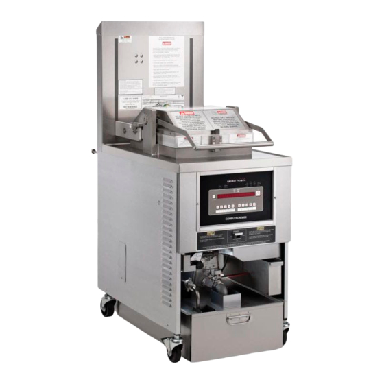
- Page 1 Henny Penny Pressure Fryer-Electric Model PFE-590 Model PFE-592 TECHNICAL MANUAL...
-
Page 3: Table Of Contents
Preventive Maintenance ... 2-1 High Temperature Limit Control ... 2-2 Fuse Holders ... 2-4 Power/Pump Switch ... 2-5 Temperature Probe Replacement ... 2-6 Complete Control Panel - Henny Penny ... 2-7 Pressure Regulation ... 2-7 2-10 Tilting the Lid Upright ... 2-8 2-11 Reversing the Lid Gasket ... - Page 4 Model 590/592...
-
Page 5: Section 1. Troubleshooting
This section provides troubleshooting information in the form of an easy to read table. If a problem occurs during the f rst operation of a new fryer, recheck the installation per the Installation Section of this Before troubleshooting, always recheck the operation pro- cedures per Section 3 of this manual. -
Page 6: Troubleshooting
1-3. TROUBLESHOOTING To isolate a malfunction, proceed as follows: Clearly def ne the problem (or symptom) and when it occurs. Locate the problem in the Troubleshooting table. Review all possible causes. Then, one-at-a-time work through the list of corrections until the problem is solved. Refer to the maintenance procedures in the Maintenance Section to safely and properly make the checkout and re- pair needed. - Page 7 • Shortening too old • Shortening too dark • Breading product too far in advance • Temperature too low • Fryer incorrect preheat • Slow fryer heat-up/recovery • Wrong cook button pushed. • Shortening old • Temperature too low •...
- Page 8 Problem D. Spotted product E. Dryness of product Product f avor (taste): A. Salty taste B. Burned taste C. Bland taste Cause COOKING SECTION (Continued) • Improper separation of the product • Breading not uniform on the product • Burned breading particles on product •...
- Page 9 Problem D. Rancid taste General: A. Meat separation from bone B. Bone color not proper C. Breading falls D. Product sticking together 1103 Cause COOKING SECTION (Continued) • Shortening too old • Infrequent f ltering • Non-compatible products cooked within the same shortening.
-
Page 10: Power Section
• Check cord and plug • Check 15 amp fuses • Turn unit off and allow fryer to cool to release pressure from frypot; clean all pressure lines, exhaust stacks, and exhaust tank • Check and clean solenoid... - Page 11 Problem Pressure does not build 1103 Cause PRESSURE SECTION (Continued) • Not enough product in fryer or product not fresh • Metal shipping spacer not removed from dead weight • Lid open or not latched • Solenoid valve leaking or not closing •...
- Page 12 Problem HEATING OF SHORTENING SECTION Shortening will not heat • Blown fuse or tripped • Blown fuse in PC board • Faulty POWER/PUMP switch. • Faulty cord and plug • Faulty drain switch • Faulty PC Board • Faulty high limit control switch •...
- Page 13 Problem HEATING OF SHORTENING SECTION (Continued) Heating of shortening too slow Shortening overheating 1103 Cause • Low or improper voltage • Weak or burnt out element(s) • Points in contactor bad • Wire(s) loose • Burnt or charred wire connection •...
- Page 14 • Condensation line stopped • Improper or bad shortening • Improper f ltering • Cold zone full of cracklings • Improper rinsing after cleaning the fryer • Drain valve clogged with crumbs • Obstruction in drain • Faulty drain valve Model 590/592 Correction •...
-
Page 15: Error Codes
1-4. ERROR CODES product DISPLAY CAUSE “E04” Control board overheating “E05” Shortening overheating “E06” Temperature probe failure “E41” Programming Failure “E71” Pump motor relay failure or wiring problem 1103 In the event of a control system failure, the digital display shows an error message. - Page 16 1-4. ERROR CODES (Continued) DISPLAY CAUSE “E10” High limit “E15” Drain Switch 1-12 CE Only - Along with the error codes from page 1-11, CE units have the following self-diagnostic error codes: PANEL BOARD CORRECTION Reset the high limit by manually pushing up on the red reset button;...
-
Page 17: Section 2. Maintenance
MAINTENANCE SECTION 2. MAINTENANCE This section provides checkout and replacement procedures, for various parts of the fryer. Before replacing any parts, refer to the Troubleshooting Section to aid you in f nding the cause of the malfunction. 1. A multimeter will help you to check electric components. -
Page 18: High Temperature Limit Control
The red reset button is located under the control panel, in the front of the fryer, to the right of the drain. Once reset, the frypot starts heating. - Page 19 2-4. HIGH TEMPERATURE LIMIT CONTROL (Continued) 1103 To avoid electrical shock of property damage, move the power switch to OFF and disconnect main circuit breaker, or unplug cord at wall receptacle. Replacement 1. If the tube is broken or cracked, the control will open, shutting off electrical power.
-
Page 20: Fuse Holders
2-4. HIGH TEMPERATURE LIMIT CONTROL (Continued) 2-5. FUSE HOLDERS 11. Pull excess capillary line from pot and tighten nut into frypot wall. Be sure capillary bulb of high limit is positioned so it does not interfere with carrier or get damaged when cleaning frypot. -
Page 21: Power/Pump Switch
The POWER/PUMP switch is a three way rocker switch with a center OFF position. With switch in the POWER position, the fryer operates. With switch in PUMP position, the f lter pump operates, but the unit will not heat. To avoid electrical shock or property damage, move the power switch to OFF and disconnect main circuit breaker, or unplug cord at wall receptacle. -
Page 22: Temperature Probe Replacement
10°C, the temperature probe should be replaced. An Ohm check can be performed also. See chart at end of this section. 1. Remove electrical power supplied to the fryer. To avoid electrical shock or property damage, move the power switch to OFF and disconnect main circuit breaker, or unplug cord at wall receptacle. -
Page 23: Complete Control Panel-Henny Penny
3. Unplug the connectors going to the control board. 4. Install a new control panel. The Henny Penny Fryer uses pressure as one of the compo- nents of the cooking process. Once the lid is sealed to the frypot, and the solenoid valve closes, a deadweight valve main- tains the correct pressure in the frypot. -
Page 24: Tilting The Lid Upright
Because of heat expansion and the pressure used for cooking process, gasket is constantly under extreme stress. Reversing the lid gasket will help to assure that the fryer will not lose pressure through leakage. 1. Put the lid in the upright position, as previously described. -
Page 25: Lid Counterweight Cables
2-12. LID COUNTERWEIGHT CABLES 1103 The Lid Counterweight in the back of the fryer balances the weight of the lid system to allow easier opening and closing of the lid. The weight has two cables attached to it, and weighs about 150 lbs. -
Page 26: Pressure Pad
2-13. PRESSURE PAD 2-10 The pressure pads are plastic strips that the lid cam presses against to seal the lid. 1. Raise the lid. 2. Remove the 4 screws securing the lid cover and remove cover 3. Push the lid cam back, off of the pressure pads. 4. -
Page 27: Lid Adjustment
If steam leaks, check for: • Pressure pad wear • Cracked or worn gasket • Gasket installed improperly • Fryer operating above 12 psi (827 mbar) Fryer should be operating at 12 psi, or serious burns could result. Model 590/592 2-11... -
Page 28: Solenoid Valve
Cook Cycle and opens automatically at the end of the Cook Cycle. If this valve should become dirty, or the Tef on seat nicked, pressure will not build up. The electric fryer uses a 208/240 volt 60 hertz coil (50 hertz internationally). - Page 29 6. Repair kit, Part No. 17120, is available if any of the seals must be replaced. If one seal is defective, replace all seals. Solenoid body must be removed from the fryer for replace ment of seals. Continue on to step 7.
-
Page 30: Deadweight Valve
14. If the complete valve is to be replaced, follow steps 1, 2, 3, 4, 5, 7, 8 and 9 in this section. DO NOT ATTEMPT TO REMOVE DEADWEIGHT CAP WHIILE FRYER IS OPERATING. SEVERE BURNS OR OTHER INJURIES WILL RESULT. The operating valves are located behind the lid. The valve, left of the pressure gauge, is a 14 1/2 lb. -
Page 31: Removal & Cleaning Of Safety Relief Valve
RELIEF VALVE. HOT STEAM WILL BE RELEASED AND SEVERE BURNS WILL RESULT. 1. At the end of each day’s usage of the fryer, the deadweight valve must be cleaned. The fryer must be OFF and pressure released. Open the lid and then remove the deadweight valve cap and deadweight. -
Page 32: Pressure Gauge
3. Clean the inside of the pipe tee with hot water. Turn the safety relief valve towards the rear of the fryer when reinstalling safety relief valve. 4. Immerse the safety relief valve in a soapy water solution for 24 hours. -
Page 33: Contactors
Primary Heat 1103 The electric fryer requires two switching contactors: a primary and a heat contactor. The primary contactor energizes (contacts close) any time the POWER/PUMP switch is in the POWER position, and the temperature of the shortening is below ( 215°... - Page 34 4. Remove the screws securing the contactor to the bracket and remove contactor from bracket. 5. Install new contactor in reverse order. 6. Install control panel and reconnect power to the fryer and test for proper operation. Model 590/592 1103...
-
Page 35: Heating Elements
2-20. HEATING ELEMENTS 1103 The electric model fryer uses 2 heating elements. Heating elements are available in 208, 220/240, 380 and 415 volts. Check the data plate, on the shroud behind the lid, to determine the correct voltage elements. 1. Remove the electrical power supplied to the unit. - Page 36 2-20. HEATING ELEMENTS (Continued) 2-20 Replacement 1. Drain the shortening. 2. Remove the high limit bulb holder from the heating element inside the frypot. 3. Disconnect the heating element wires from the contactors. Label each so it can be replaced in the same position on the new element.
- Page 37 2-20. HEATING ELEMENTS (Continued) 1103 10. Replace the brass nuts and washers on the heating element terminals. Tighten the brass nuts to 30 foot lbs of torque. 11. Replace heat contactor. 12. Move the element spreaders from the center of the ele ment, into a position which will spread each element apart evenly on all four sides, and tighten.
-
Page 38: Drain Microswitch
2-21. DRAIN MICROSWITCH 1/8” (4 mm) Gap 2-22 Upon pulling out on the drain handle, the microswitch should be activated and the unit will not heat, but when the handle is pushed back, the unit should operate properly. The bracket on the microswitch is slotted so it can be adjusted backward or forward. -
Page 39: Drain Valve And Extension
2-22. DRAIN VALVE AND EXTENSION 1103 The drain valve opens when the drain valve handle is pulled out and drains the shortening out of the pot. Replacement 1. Using a 3/8” socket, remove the nuts securing the drain switch bracket, and pull the bracket from the studs. 2. -
Page 40: Nylatron Strips Replacement
2-23. NYLATRON STRIPS REPLACEMENT 2-24 1. Raise the lid and remove the retention ring from one end of the lid pin. 2. Slide the lid pin from unit. 3. Lift the lid from unit. The lid weighs 80 lbs (36 kg). Take care when lifting lid to prevent personal injury. - Page 41 2-23. NYLATRON STRIPS REPLACEMENT (Continued 1103 9. Lift the front shroud up and out, over the arm of the lid. 10. Thread the new nylatron strip through the track in the front shroud. 11. Lining up the holes in the strips, f t the front shroud back over the lid arms.
- Page 42 Model 590/592 SN: AC0608030 & below 2-26 1203...
- Page 43 Model 590/592 SN: AC0608031 & above 2-27...
- Page 44 Model 590/592 SN: AC0608030 & below 2-28 1203...
- Page 45 Model 590/592 SN: AC0608031 & above 2-29...
- Page 46 Model 590/592 SN: AC0608030 & below 2-30 1203...
- Page 47 Model 590/592 SN: AC0608031 & above 2-31...
- Page 48 Model 590/592 SN: AC0608030 & below 2-32 1203...
- Page 49 Model 590/592 SN: AC0608031 & above 2-33...
- Page 50 Model 590/592 SN: AC0608030 & below 2-34 1203...
- Page 51 Model 590/592 SN: AC0608031 to 10-4-07 1107 2-35...
- Page 52 Model 590/592 10-4-07 & After 2-36 1107...
- Page 53 Model 590/592 Before 10-4-07 1107 2-37...
- Page 54 Model 590/592 10-4-07 & After 2-38 1107...
-
Page 55: Section 3. Parts Information
This section lists the replaceable parts of the Henny Penny Model 590 fryer. Use only genuine Henny Penny parts in your fryer. Using a part of lesser quality or substitute design may result in damage to the unit or personal injury. - Page 56 3-8. INDEX OF PARTS LIST ILLUSTRATIONS FRAME & COVER ASSEMBLY... ELEMENT ASSEMBLY ... COUNTERWEIGHT SYSTEM ... LID & COVER ASSEMBLY ... STEAM BOX & HOSE ASSEMBLY ... DEADWEIGHT & SOLENOID ASSEMBLY ... SOLENOID VALVE ASSEMBLY ... FAST READY PARTS ... CONTROL PANEL ASSEMBLY ...
- Page 57 Model 590/592 FIGURE 3-1. FRAME & COVER ASSEMBLY...
- Page 58 Figure & Item No. Part No. 39796 53669 3 29898 54225 35154 37246 SC03-005 66934 SC01-215 37291 35726 66933 14457 36337 SC02-023 62085 recommended parts Description FRAME & COVER ASSEMBLY WELDMENT – CONTROL PANEL FRONT ... GUARD – POWER SWITCH ... SWITCH –...
- Page 59 Figure & Item No. Part No. SC01-083 35101 35100 SC01-074 35435 35462 7 35234 35598 48367 36290 16855 WA01-005 NS01-017 recommend. parts Description ELEMENT ASSEMBLY SCREW, (#10-32 x 1/2 PH FHD) SUPPORT, ELEMENT - LONG ...
- Page 60 Figure & Item No. Part No. 35026 35207 NS01-025 LW01-010 35092 SC01-069 36839 SC01-042 36625 36627 36626 37362 37363 37364 SC01-081 35962 36561 35964 SC01-132 recommended parts Description COUNTERWEIGHT SYSTEM ARM, LID SUPPORT ... CABLE ... NUT, HEX 5/16-18 SS ... WASHER, 3/8 SPLIT RING SS...
- Page 61 Model 590/592 3-4. LID & COVER ASSEMBLY...
- Page 62 Figure & Item No. Part No. 35792 35675 35243 35413 52627 49852 SC01-204 49962 49890 35359 RR01-004 WA01-020 51531 SC01-074 35223 35227 35339 SC01-062 SC01-041 36285 34526 66620 35945 52497 52498 59169 51707 LW02-006 SC01-248 35032 RR01-010...
- Page 63 Figure & Item No. Part No. 35686 MS01-297 35693 35696 SC02-041 66732 82517 66723 62211 69263 MS01-315 NS01-011 36851 21877 71409 EF02-118 * not shown Description STEAM BOX & HOSE ASSY TUBE, DW TO EXHAUST STACK SS ... HOSE CLAMP, SS - .500 – 1.062 DID ... TUBE, EXHAUST CONNECT ...
- Page 64 Model 590/592 3-6. DEADWEIGHT & SOLENOID ASSEMBLY 3-10 1203...
- Page 65 Figure & Item No. Part No. 1 16910 2 59742 FP01-127 FP01-063 FP01-011 FP01-028 17407 16817 16809 56307 16902 16903 65449 81343 16918 16852 35686 35817 16804 35200 35474 FP01-066 16807 35147 18721 18724 16808 recommended parts Description DEADWEIGHT &...
- Page 66 Model 590/592 3-7. SOLENOID VALVE ASSEMBLY 3-12 1005...
-
Page 67: Solenoid Valve Assembly
Figure & Item No. Part No. 18721 18724 2* 17120 17101 17109 17110 17111 17112 17114 17115 17116 17117 17122 13 17102 14 17103 15 17104 16 17105 17 18706 ... - Page 68 Model 590/592 3-8. FAST READY PARTS 3-14 1203...
- Page 69 LIGHT - CE INDICATOR, GREEN ... LIGHT - INDICATOR, RED ... SWITCH MAIN ASSY - 4 PDT ... SWITCH COVER ... GUARD - SWITCH FRYER ... NUT - 3/4-32 JAM ... NUT HEX KEPS #8-32 C ... BUSHING 33/64 P ...
- Page 70 Figure & Item No. Part No. 1 70949RB 1 23720RB 50624 54922 78950 NS02-005 5 51877 SC01-049 NS02-005 72500 14621 recommended part/* not shown 3-16 Description CONTROL PANEL ASSEMBLY CONTROL ASSY-590 SMS-W/O SETPOINTS-INT’L CONTROL ASSY –...
- Page 71 Figure & Item No. Part No. 3-10 1 29942 1* 65075 1* 77574 1* 65074 2 30971 3 19405 4 17216 5 16738 5 60241 ...
- Page 72 Model 590/592 Pump Interior 3-11A. FILTER PUMP ASSEMBLY (SN: LG012JC & BELOW) 3-18 1005...
- Page 73 Figure & Item No. Part No. 3-11A 18107 54484 3 17476 18105 18644 51831 55836 16808 16809 17407 11 67583 14669 62206 13 17430(use69289) 16807 FP01-122 FP02-024 17 35472 FP02-007 17437 20 17454 ...
- Page 74 Model 590/592 Pump Interior 3-11B. FILTER PUMP ASSEMBLY (SN: LG013JC & ABOVE) 3-20 1203...
- Page 75 Figure & Item No. Part No. 3-11B 18107 54484 3 17476 18105 18644 51831 66618 FP01-169 11 67583 12 FP01-089 17407 62206 15 17430(use69289) 16 21800 FP02-021 FP02-033 64218 19 SC01-132 ...
- Page 76 Figure & Item No. Part No. 3-12 65520 66553 SC01-058 WA01-006 4 54228 NS02-005 52519 65522 67619 EF02-017 67617 76579 recommended part 3-22 Description DRAIN VALVE & DRAIN SWITCH ASSEMBLIES DRAIN VALVE ASSEMBLY (SN: LG012JC & BELOW) DRAIN VALVE ASSEMBLY (SN: LG013JC &...
- Page 77 Model 590/592 3-13. DRAIN PAN AND FILTER ASSEMBLY 3-23...
- Page 78 Figure & Item No. Part No. 3-13 52194 03203 21471 24491 52496 52487 SC01-009 NS02-002 17505 17503(use 14674) 65447 17502(use 14674) 36305 24212 14658 12 17431(use 69289) 13 17432(use 69289) 24211 23740 SC01-245 23804 OR01-007 23803 66535 62082 ...
- Page 79 1209 Description CARRIER, RACKS & JUNCTION BOX ASSY CARRIER ASSY ... RACK HALF SIZE – 8 HEAD FRYER ... WELDMENT - RACK HANDLE ... JUNCTION BOX ASSY ... JUNCTION BOX ASSY - CE ... ASSY - 5-POLE TERMINAL BLOCK - CE ...
- Page 80 Model 590/592...
Need help?
Do you have a question about the HENNY PENNY PFE-590 and is the answer not in the manual?
Questions and answers