Honeywell UDC2500 Product Manual
Honeywell universal digital controller product manual
Hide thumbs
Also See for UDC2500:
- Product manual (108 pages) ,
- Manual (8 pages) ,
- Quick start manual (2 pages)
Table of Contents
Advertisement
Quick Links
Download this manual
See also:
Manual
Advertisement
Table of Contents
Troubleshooting

Related Manuals for Honeywell UDC2500


Summary of Contents for Honeywell UDC2500
- Page 1 UDC2500 Universal Digital Controller Product Manual 51-52-25-127 April 2007 Honeywell Process Solutions Industrial Measurement and Control...
-
Page 2: Notices And Trademarks
Contact your local sales office for warranty information. If warranted goods are returned to Honeywell during the period of coverage, Honeywell will repair or replace without charge those items it finds defective. The foregoing is Buyer's sole remedy and is in lieu of all other warranties, expressed or implied, including those of merchantability and fitness for a particular purpose. -
Page 3: About This Document
This document provides descriptions and procedures for the Installation, Configuration, Operation, and Troubleshooting of your UDC2500 Controller. Contacts World Wide Web The following lists Honeywell’s World Wide Web sites that will be of interest to our customers. Honeywell Organization Corporate Industrial Measurement and Control... -
Page 4: Symbol Definitions
Chassis Ground. Identifies a connection to the chassis or frame of the equipment shall be bonded to Protective Earth at the source of supply in accordance with national and local electrical code requirements. 4/07 UDC2500 Universal Digital Controller Product Manual Definition... -
Page 5: Table Of Contents
Options Group ...67 3.13 Communications Group ...73 3.14 Alarms Set Up Group ...76 3.15 Display Set Up Group ...82 3.16 P.I.E. Tool Ethernet and Email Configuration Screens...84 3.17 Configuration Record Sheet ...87 UDC2500 Universal Digital Controller Product Manual Contents Introduction 4/07... - Page 6 Setpoint Ramp/Soak Programming ...118 4.22 P.I.E. Tool Maintenance Screens ...125 4.23 Configuring your Ethernet Connection ...131 INPUT CALIBRATION... 136 Overview...136 Minimum and Maximum Range Values ...137 Preliminary Information...139 Input 1 Set Up Wiring...140 4/07 UDC2500 Universal Digital Controller Product Manual...
- Page 7 9.4.1 Write Configuration Examples ...188 MODBUS READ, WRITE AND OVERRIDE PARAMETERS PLUS EXCEPTION CODES...189 10.1 Overview ...189 10.2 Reading Control Data...190 10.3 Read Software Options Status ...191 10.4 Miscellaneous Read Onlys ...192 UDC2500 Universal Digital Controller Product Manual Introduction 4/07...
- Page 8 Overview ...220 FURTHER INFORMATION... 221 12.1 Modbus RTU Serial Communications ...221 12.2 Modbus Messaging on TCP/IP...221 12.3 How to Apply Digital Instrumentation in Severe Electrical Noise Environments...221 INDEX ...222 SALES AND SERVICE... 226 4/07 UDC2500 Universal Digital Controller Product Manual viii...
- Page 9 Table 4-21 Procedure for Displaying 3Pstep Motor Position_________________________________ 113 Table 4-22 Procedure for Setting a Failsafe Value_________________________________________ 114 Table 4-23 Procedure for Setting a Failsafe Mode_________________________________________ 115 Table 4-24 Running A Setpoint Ramp __________________________________________________ 116 Table 4-25 Program Contents_________________________________________________________ 118 UDC2500 Universal Digital Controller Product Manual 4/07...
- Page 10 Table 10-2 Option Status ____________________________________________________________ 191 Table 10-3 Miscellaneous Read Onlys__________________________________________________ 192 Table 10-4 SetPoint Program Read Only Information ______________________________________ 192 Table 10-5 Setpoint Code Selections ___________________________________________________ 193 Table 10-6 Setpoint Associated Parameters ______________________________________________ 193 4/07 UDC2500 Universal Digital Controller Product Manual...
- Page 11 Table 10-18 Set-up Group – Communications____________________________________________ 213 Table 10-19 Set-up Group – Alarms ___________________________________________________ 214 Table 10-20 Set-up Group – Display ___________________________________________________ 217 Table 10-21 Modbus RTU Data Layer Status Exception Codes ______________________________ 219 UDC2500 Universal Digital Controller Product Manual 4/07...
- Page 12 Figure 3-1 Ethernet Configuration Screen ________________________________________________ 84 Figure 3-2 Email Configuration Screen __________________________________________________ 85 Figure 4-1 Operator Interface __________________________________________________________ 90 Figure 4-2 Functional Overview Block Diagram of the UDC2500 Controller ____________________ 96 Figure 4-3 Ramp/Soak Profile Example_________________________________________________ 121 Figure 4-4 Program Record Sheet _____________________________________________________ 122...
- Page 13 Figure 5-9 Wiring Connections for 0 to 2 Volts, 0 to 5 Volts or 1 to 5 Volts Input – Input 2 ________ 147 Figure 6-1 Wiring Connections for Calibrating Current Output ______________________________ 152 Figure 6-2 Wiring Connections for Calibrating Auxiliary Output _____________________________ 154 Figure 8-1 UDC2500 Exploded View __________________________________________________ 177 Figure 10-1 Software Option Status Information __________________________________________ 191 xiii...
-
Page 15: Introduction
1.1 Overview Function The UDC2500 is a microprocessor-based stand-alone controller. It combines a high degree of functionality and operating simplicity in a 1/4 DIN size controller. This instrument is an ideal controller for regulating temperature and other process variables in numerous heating and cooling applications, as well as in metal working, food, pharmaceuticals, semiconductor, testing and environmental work. -
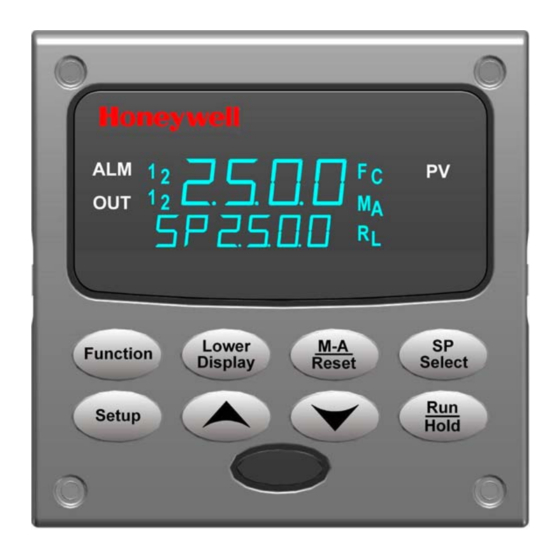
Page 16: Figure 1-1 Udc2500 Operator Interface (All Display Items Shown)
NEMA4X and IP66 for the most severe hose-down applications. It withstands ambient temperatures up to 55°C (133°F) and resists the effects of vibration and shock. Figure 1-1 UDC2500 Operator Interface (all display items shown) UDC2500 Universal Digital Controller Product Manual 4/07... -
Page 17: Function Of Displays And Keys
Note 2: Value can be changed via increment/decrement keys. Note 3: The selected set can be changed via increment/decrement keys. 4/07 UDC2500 Universal Digital Controller Product Manual Table 1-1Function of Displays and Keys Function Lower display automatically displays setpoint value in engineering units. -
Page 18: Process Instrument Explorer Software
PC, a Desktop or a laptop computer. · • Create/edit configurations live, just connect software to controller via comm port.· • Create/edit configurations offline and download to controller later via comm. port.· • Port types available on every UDC2500:· o Infrared o RS 485 o Ethernet •... -
Page 19: Ce Conformity (Europe)
Enclosure Rating: This controller must be panel-mounted with the rear terminals enclosed within the panel. The front panel of the controller is rated at NEMA4X and IP66 when properly installed. Installation Category (Overvoltage Category): Category II (EN61010-1) 4/07 UDC2500 Universal Digital Controller Product Manual Introduction... - Page 20 WARNING If this equipment is used in a manner not specified by the manufacturer, the protection provided by the equipment may be impaired. UDC2500 Universal Digital Controller Product Manual 4/07...
-
Page 21: Installation
2.1 Overview Introduction Installation of the UDC2500 consists of mounting and wiring the controller according to the instructions given in this section. Read the pre-installation information, check the model number interpretation (Subsection 2.3), and become familiar with your model selections, then proceed with installation. -
Page 22: Pre-Installation Information
• Check that the model number shown on the inside of the case agrees with what you have ordered. 2.2 Condensed Specifications Honeywell recommends that you review and adhere to the operating limits listed in Table 2-1 when you install your controller. Accuracy: Analog Inputs ±... - Page 23 Relay Contacts: with a working voltage of 115/230 Vac, are isolated from each other and all other circuits at 345Vdc for 2 seconds. 4/07 UDC2500 Universal Digital Controller Product Manual Specifications ϕ = 0.4): 3 amps @ 130 Vac or 250 Vac ϕ...
- Page 24 Otherwise, the instruments may not start up normally due to voltage drop from the inrush current. Weight 3 lbs. (1.3 kg) UDC2500 Universal Digital Controller Product Manual Specifications When applying power to more than one instrument, make sure that sufficient 4/07...
- Page 25 (For Vac) * The maximum moisture rating only applies up to 40 °C (104 °F). For higher temperatures, the RH specification is derated to maintain constant moisture content. 4/07 UDC2500 Universal Digital Controller Product Manual Rated Operative Limits 15 to 55 °C 0 to 55 °C...
-
Page 26: Model Number Interpretation
Key Number _ _ _ _ _ _ _ _ _ _ KEY NUMBER - UDC2500 Single Loop Controller Digital Controller for use with 90 to 264Vac Power Digital Controller for use with 24Vac/dc Power TABLE I - Specify Control Output and/or Alarms... -
Page 27: Figure 2-1 Model Number Interpretation
Table Limit Controller Restrictions/Comments: 1. FM approved units with communications are limited to read only. 2. UL listed for regulatory use only. Figure 2-1 Model Number Interpretation 4/07 UDC2500 Universal Digital Controller Product Manual (51-52-25-127) (51-52-25-127-FR) (51-52-25-127-DE) (51-52-25-127-IT) (51-52-25-127-SP) Not Available With... -
Page 28: Control And Alarm Relay Contact Information
If power is lost to the unit, the alarms will de-energize and thus the alarm contacts will close. Table 2-3 Alarm Relay Contact Information Unit Alarm Relay Power Wiring N.O. N.C. N.O. N.C. UDC2500 Universal Digital Controller Product Manual Control Relay Control Relay Wiring Contact N.O. Open N.C. Closed N.O. Open Closed N.C. -
Page 29: Mounting
- 0,00 Panel 3,62 + 0,03 Cutout -0,00 92,0 + 0,8 3,62 + 0,03 Figure 2-2 Mounting Dimensions (not to scale) 4/07 UDC2500 Universal Digital Controller Product Manual Max. panel thickness 19,1 113,1 - 0,00 4,45 17,9 0,70 -0,00 Installation... -
Page 30: Table 2-4 Mounting Procedure
(Figure 2-3). Push the point of the screw through the center piercing the elastomeric material and then tighten screws to 5 lb-in (56 N•cm). UDC2500 Universal Digital Controller Product Manual Figure 2-3 Mounting Methods Table 2-4 Mounting Procedure... -
Page 31: Wiring
Vac, 42.4 Vpeak, or 60 Vdc) wiring per Permissible Wiring Bundling, Table 2-5. Electrical Noise Precautions Electrical noise is composed of unabated electrical signals which produce undesirable effects in measurements and control circuits. 4/07 UDC2500 Universal Digital Controller Product Manual Installation ) copper... -
Page 32: Table 2-5 Permissible Wiring Bundling
For additional noise information, refer to document number 51-52-05-01, How to Apply Digital Instrumentation in Severe Electrical Noise Environments. Permissible Wiring Bundling Table 2-5 Permissible Wiring Bundling Bundle No. UDC2500 Universal Digital Controller Product Manual Wire Functions • Line power wiring • Earth ground wiring • Line voltage control relay output wiring •... -
Page 33: Wiring Diagrams
Output 1 is OPEN and Output 2 is CLOSE. In Table 2-6 the Output 1/2 option Single Relay can be any of the following selections: Electro-Mechanical Relay, Solid-State Relay or Open Collector Output. 4/07 UDC2500 Universal Digital Controller Product Manual Installation... -
Page 34: Table 2-6 Universal Output Functionality And Restrictions
* To obtain this output algorithm type with these Output 1/2 Options: 1) Configure the OUTALG selection as “TIME D”; 2) Configure Auxiliary Output for “OUTPUT” and; 3) Scale the Auxiliary Output as necessary for the desired output algorithm type. For these UDC2500 Universal Digital Controller Product Manual Function of Output 1/2... -
Page 35: Wiring The Controller
Input #2 Terminals. See Figure 2-7. Input #1 Terminals. See Figure 2-6. Aux. Output and Digital Inputs Terminals. See Figure 2-17. Communications Terminals. See Figure 2-15 and Figure 2-16. 4/07 UDC2500 Universal Digital Controller Product Manual L2/N See table for callout details Details Installation... -
Page 36: Figure 2-5 Mains Power Supply
90-264 Vac applications; or 1 A, 125 V fuse or circuit breaker for 24 Vac/dc applications, as part of the installation. CAUTION Applying 90-264 Vac to an instrument rated for 24 Vac/dc will severely damage the instrument and is a fire and smoke hazard. UDC2500 Universal Digital Controller Product Manual Earth Ground Neutral... -
Page 37: Figure 2-6 Input 1 Connections
The millivolt values for the Thermocouple Differential Input are for a pair of J thermocouples at an ambient temperature mean of 450°F / 232°C. an ambient temperature mean of 450°F / 232°C. 4/07 UDC2500 Universal Digital Controller Product Manual – – –... -
Page 38: Figure 2-7 Input 2 Connections
Electromechanical relays are rated at 5 Amps @ 120 Vac or 240 Vac or 30 Vdc. Customer should size fuses accordingly. Use Fast Blo fuses only. Figure 2-8 Electromechanical Relay Output See Table 2-6 for relay terminal connections for other Output Algorithm Types. UDC2500 Universal Digital Controller Product Manual Milliamps Input – 22 mA+... -
Page 39: Figure 2-9 Solid State Relay Output
Customer should size fuses accordingly. Use Fast Blo fuses only. Figure 2-9 Solid State Relay Output See Table 2-6 for relay terminal connections for other Output Algorithm Types. 4/07 UDC2500 Universal Digital Controller Product Manual Time Simplex Output Relay#1 N.O. -
Page 40: Figure 2-10 Open Collector Output
Electromechanical relays are rated at 5 Amps @ 120 Vac or 240 Vac or 30 Vdc. Customer should size fuses accordingly. Use Fast Blo fuses only. Figure 2-10 Open Collector Output See Table 2-6 for relay terminal connections for other Output Algorithm Types. UDC2500 Universal Digital Controller Product Manual Time Simplex Output #1 L2/N –... -
Page 41: Figure 2-11 Dual Electromechanical Relay Option Output
Electromechanical relays are rated at 5 Amps @ 120 Vac or 240 Vac or 30 Vdc. Customer should size fuses accordingly. Use Fast Blo fuses only. See Table 2-6 for relay terminal connections for other Output Algorithm Types. 4/07 UDC2500 Universal Digital Controller Product Manual Time Duplex with a Dual Relay Board Out Relay#2 N.O. -
Page 42: Figure 2-13 Three Position Step Control Connections W/O Dual Relay Option
30 Vdc. Customer should size fuses accordingly. Use Fast Blo fuses only. 30 Vdc. Customer should size fuses accordingly. Use Fast Blo fuses only. Figure 2-14 Three Position Step Control Connections with Dual Relay UDC2500 Universal Digital Controller Product Manual Open (CW) Close (CCW) -
Page 43: Figure 2-15 Rs-422/485 Communications Option Connections
Figure 2-16 and Table 2-7 shows how to connect a UDC to a MDI Compliant Hub or Switch utilizing a straight-through cable or for connecting a UDC to a PC utilizing a crossover cable. 4/07 UDC2500 Universal Digital Controller Product Manual COMMUNICATION MASTER D+ (B) SHLD SHLD D–... -
Page 44: Table 2-7 Terminals For Connecting A Udc To A Mdi Compliant Hub Or Switch
Connect shield to ground at one end only. Auxiliary Output and Digital Input 2 are mutually exclusive. Figure 2-17 Auxiliary Output and Digital Inputs Option Connections UDC2500 Universal Digital Controller Product Manual RJ45 Socket Pin # Shield Shield RXD- RXD+... -
Page 45: Figure 2-19 Transmitter Power For 4-20 Ma - 2 Wire Transmitter Using Auxiliary Output
A 1N4733 will reduce the voltage at the transmitter to approximately 25 Vdc. Figure 2-19 Transmitter Power for 4-20 mA — 2 Wire Transmitter 4/07 UDC2500 Universal Digital Controller Product Manual 2 Wire Transmitter Configure: A2S1TY = NONE A2S2TY = NONE 250 Ω... -
Page 46: Configuration
3.13 Communications Set Up Group 3.14 Alarms Set Up Group 3.15 Display Set Up Group 3.16 P.I.E. Tool Ethernet and Email Configuration Screens 3.17 Configuration Record Sheet UDC2500 Universal Digital Controller Product Manual 3 Configuration Table 3-1 Configuration Topics TOPIC See Page... -
Page 47: Configuration Prompt Hierarchy
PBorGN OPTIONS AUXOUT ComADD SDMODE ALARMS A1S1TY A2S1TY ALHYST DISPLY DECMAL STATUS VERSON 4/07 UDC2500 Universal Digital Controller Product Manual Function Prompts RATE T I MIN or MANRST I RPM SECUR LOCK AUTOMA TI MIN FINLSP SPRATE RPUNIT RECYCL SOKDEV * x = 1 to 12. -
Page 48: Configuration Procedure
Parameter Change the Value or Selection Enter the Value or Selection Exit Configuration UDC2500 Universal Digital Controller Product Manual Press Upper Display = SET Setup Setup Lower Display = TUNING (This is the first Set Up Group title) Sequentially displays the other Set Up group titles shown in... -
Page 49: Tuning Set Up Group
Gain = 0.01 to 1000 RATE T 0.00 to 10.00 minutes 0.08 or less = OFF 4/07 UDC2500 Universal Digital Controller Product Manual Upper Display English Numeric Code PROPORTIONAL BAND (simplex) is the percent of the range of the measured variable for which a proportional controller will produce a 100 % change in its output. - Page 50 Gain = 0.01 to GAIN 2 1000 RATE2T 0.00 to 10.00 minutes 0.08 or less = OFF UDC2500 Universal Digital Controller Product Manual Upper Display English Numeric Code Also defined as "HEAT" Rate on Duplex models for variations of Heat/Cool applications.
- Page 51 1 to 120 CT2 X3 SECUR 0 to 9999 LOCK NONE 4/07 UDC2500 Universal Digital Controller Product Manual Upper Display English Numeric Code These are the same as above except that they apply to Duplex models for the "COOL" zone of Heat/Cool applications or for the second set of PID constants.
- Page 52 Code CONF VIEW AUTOMA ENAB RN HLD ENAB SP SEL ENAB UDC2500 Universal Digital Controller Product Manual Upper Display English Numeric Code read/write. CALIBRATION—All groups are available for read/write except for the Calibration and Keyboard Lockout groups. + CONFIGURATION—Tuning, SP Ramp, and Accutune groups are read/write.
-
Page 53: Sp Ramp Set Up Group
SP Ramp prompts to appear 0 to 255 minutes TI MIN 4/07 UDC2500 Universal Digital Controller Product Manual RUN/HOLD Upper Display English Numeric Code SINGLE SETPOINT RAMP—Make a selection to enable or disable the setpoint ramp function. Make sure you configure a ramp time and a final setpoint value. - Page 54 Ramp and SP Programming are disabled EUHRUP 0 to 9999 in Engineering units per hour UDC2500 Universal Digital Controller Product Manual Upper Display English Numeric Code SETPOINT RAMP FINAL SETPOINT— Enter the value desired for the final setpoint. The controller will operate at the setpoint set here when ramp is ended.
- Page 55 SOKDEV 0 to 100 PG END LAST (Hold at last SP) FSAF (Manual mode/failsafe) 4/07 UDC2500 Universal Digital Controller Product Manual Upper Display English Numeric Code RATE DOWN—Rate down value. When making a setpoint change, this is the rate at which the controller will change from the original setpoint down to the new one.
- Page 56 SG2 TI 0-99 Hours:0-59 SG4 TI Minutes SG6 TI SG8 TI SG10TI SG12TI UDC2500 Universal Digital Controller Product Manual Upper Display English Numeric Code Program State at Program End Reset/Rerun SP Program DISABLE—LSP1 is used as the initial ramp setpoint.
-
Page 57: Accutune Set Up Group
SP value and alters the output over the Output Limit Range. Duplex Tuning is used when a Duplex Control Algorithm is configured. To perform a Duplex Tune, Two Local Setpoints must be configured per the Control Group in Section 3.11. 4/07 UDC2500 Universal Digital Controller Product Manual Configuration... -
Page 58: Table 3-6 Atune Group (Numeric Code 300) Function Prompts
Numeric Code FUZZY ENAB TUNE TUNE DUPLEX MANU AUTO UDC2500 Universal Digital Controller Product Manual Upper Display English Numeric Code FUZZY OVERSHOOT SUPPRESSION— Can be enabled or disabled independently of whether Demand Tuning or SP Tuning is enabled or disabled. - Page 59 Numeric Code AT ERR (Read Only) NONE ABRT 4/07 UDC2500 Universal Digital Controller Product Manual Upper Display English Numeric Code DISABLE – The current SetPoint is used to derive a single set of blended tuning parameters. This tuning is performed over the range of the output limits similar to Simplex Tuning.
-
Page 60: Algorithm Set Up Group
Selection or Range of Setting Lower Display English Numeric Code CTRALG ONOF UDC2500 Universal Digital Controller Product Manual key) or Alarm 2. An optional digital input can also be RUN/HOLD Upper Display English Numeric Code The CONTROL ALGORITHM lets you select the type of control that is best for your process. - Page 61 Lower Display English Numeric Code PIDA PIDB 4/07 UDC2500 Universal Digital Controller Product Manual Upper Display English Numeric Code DUPLEX ON/OFF is an extension of this algorithm when the output is configured for Duplex. It allows the operation of a second ON/OFF output.
- Page 62 Selection or Range of Setting Lower Display English Numeric Code PDMR TPSC UDC2500 Universal Digital Controller Product Manual Upper Display English Numeric Code PD WITH MANUAL RESET is used whenever integral action is not wanted for automatic control. The equation is computed with no integral contribution.
- Page 63 Select length of time in Hours and Minutes, or minutes and seconds. START 4/07 UDC2500 Universal Digital Controller Product Manual Upper Display English Numeric Code The actual slidewire position is then shown on the lower display as POS. This value is used for display only.
- Page 64 English Numeric Code L DISP TREM RESET INCRMT UDC2500 Universal Digital Controller Product Manual Upper Display English Numeric Code L DISP allows you to select whether time remaining (TI REM) or elapsed time (E TIME) is displayed for the timer option.
-
Page 65: Output Set Up Group
Selection or Range of Setting Lower Display English Numeric Code OUTALG RLY2 4/07 UDC2500 Universal Digital Controller Product Manual Upper Display English Numeric Code The OUTPUT ALGORITHM lets you select the type of output you want. Not applicable with Control algorithm prompt TPSC (Three Position Step Control). - Page 66 CURD CURT TCUR CRANGE 4-20 0-20 OUTRNG UDC2500 Universal Digital Controller Product Manual Upper Display English Numeric Code CURRENT SIMPLEX—Type of output using one 4 mA to 20 mA signal that can be fed into a positive or negative grounded load of 0 to 1000 ohms.
- Page 67 Function Prompt Selection or Range of Setting Lower Display English Numeric Code 4/07 UDC2500 Universal Digital Controller Product Manual Upper Display English Numeric Code CURRENT DUPLEX RANGE (SPLIT)—This setting should be used for Relay/Current and Current/Relay Duplex Outputs. It can also be used for Current Duplex when an Auxiliary Output board is present.
- Page 68 Lower Display English Numeric Code RLY TYP MECH 5 to 1800 seconds MTR TI UDC2500 Universal Digital Controller Product Manual Upper Display English Numeric Code RELAY CYCLE TIME INCREMENT selection is used only for Time Simplex and Duplex output configurations. This...
-
Page 69: Input 1 Set Up Group
100L RADH RADI 0-20 4-20 100m 0-10 TDIF 4/07 UDC2500 Universal Digital Controller Product Manual Upper Display English Numeric Code INPUT 1 ACTUATION TYPE – This selection determines what actuation you are going to use for Input 1. B—B Thermocouple E H—E Thermocouple High... - Page 70 100L RADH RADI −999 to 9999 IN1 HI floating in engineering units UDC2500 Universal Digital Controller Product Manual Upper Display English Numeric Code TRANSMITTER CHARACTERIZATION— This selection lets you instruct the controller to characterize a linear input to represent a non-linear one.
- Page 71 -999 to 9999 0 to 120 seconds FILTR1 0 = No Filter BRNOUT NONE 4/07 UDC2500 Universal Digital Controller Product Manual Upper Display English Numeric Code INPUT 1 LOW RANGE VALUE in engineering units is displayed for all inputs but can only be configured for linear or square root transmitter characterization.
- Page 72 English Numeric Code DOWN NOFS EMISS 0.01 to 1.00 UDC2500 Universal Digital Controller Product Manual Upper Display English Numeric Code DOWNSCALE BURNOUT will force the Input 1 signal to the lower range value when the sensor fails. Diagnostic message IN1 FAIL intermittently flashed on the lower display.
-
Page 73: Input 2 Set Up Group
NNML NIC H NIC L 100H 100L RADH RADI 4/07 UDC2500 Universal Digital Controller Product Manual Upper Display English Numeric Code INPUT 2 ACTUATION TYPE – This selection determines what actuation you are going to use for Input 2. DIS—Disable 0-20—0 to 20 mA (internal dropping resistor) - Page 74 -20.0 to 20.0 RATIO2 -999 to 9999 BIAS 2 FILTR2 0 to 120 seconds 0 = No Filter UDC2500 Universal Digital Controller Product Manual Upper Display English Numeric Code INPUT 2 HIGH RANGE VALUE in engineering units is displayed for all inputs but can only be configured for linear or square root transmitter characterization.
-
Page 75: Control Set Up Group
Selection or Range of Setting Lower Display English Numeric Code PIDSET 2KBD 4/07 UDC2500 Universal Digital Controller Product Manual Upper Display English Numeric Code NUMBER OF TUNING PARAMETER SETS—This selection lets you choose one or two sets of tuning constants (gain, rate, and reset). - Page 76 2 SP SW VAL Value in engineering units within PV or SP range limits LSP’S UDC2500 Universal Digital Controller Product Manual Upper Display English Numeric Code TWO SETS PV AUTOMATIC SWITCHOVER—When the process variable is GREATER than the value set at prompt...
- Page 77 NONE INP2 SP TRK NONE PROC PWR UP ALSP 4/07 UDC2500 Universal Digital Controller Product Manual Upper Display English Numeric Code TWO LOCAL SETPOINTS—This selection lets you switch between two local setpoints using the SETPOINT SELECT key. REMOTE SETPOINT SOURCE— This...
- Page 78 0 to 100 % of the SP Hi PV range 0 to 100 % of the SP Lo PV range ACTION UDC2500 Universal Digital Controller Product Manual Upper Display English Numeric Code AUTOMATIC MODE, LAST RSP—At power-up, the controller will use automatic mode with the last remote setpoint used before power down displayed.
- Page 79 0.5 to 5.0 % HYST 0.0 to 100.0 % of FAILSF 0 to 100 % FAILSF 4/07 UDC2500 Universal Digital Controller Product Manual Upper Display English Numeric Code HIGH OUTPUT LIMIT—This is the highest value of output beyond which you do not want the controller automatic output to exceed.
- Page 80 SP = 1500 and the SP HiLIM is changed to 1200, the new local setpoint will be 1200. NOTE 5: Reset limits and Dropoff are not displayed when Three Position Step Control is configured. UDC2500 Universal Digital Controller Product Manual Upper Display...
-
Page 81: Options Group
Selection or Range of Setting Lower Display English Numeric Code AUXOUT PROC 4/07 UDC2500 Universal Digital Controller Product Manual Upper Display English Numeric Code AUXILIARY OUTPUT SELECTION This selection provides an mA output representing one of several control parameters. The display for auxiliary output viewing will be in engineering units for all but output. - Page 82 English Numeric Code LSP 1 LSP 2 0PCT Value in Engineering Units UDC2500 Universal Digital Controller Product Manual Upper Display English Numeric Code DEVIATION (PROCESS VARIABLE MINUS SETPOINT)—Represents –100 % to +100 % of the selected PV span in engineering units.
- Page 83 100 PCT Engineering Units 4-20 CRANGE 0-20 DIGIN1 NONE 4/07 UDC2500 Universal Digital Controller Product Manual Upper Display English Numeric Code AUXILIARY OUTPUT HIGH SCALING FACTOR— This is a value in engineering units used to represent all AUX OUT parameters except Output.
- Page 84 Numeric Code HOLD PID2 Begn NO I MNFS LOCK UDC2500 Universal Digital Controller Product Manual Upper Display English Numeric Code TO HOLD—Contact closure suspends Setpoint Program or Setpoint Ramp. When contact reopens, the controller starts from the Hold point of the Ramp/Program unless the Ramp/Program was not previously started via the RUN/HOLD key.
- Page 85 Numeric Code TIMR TUNE INIT MNLT TRAK STRT 4/07 UDC2500 Universal Digital Controller Product Manual Upper Display English Numeric Code TIMER—Contact closure starts timer, if enabled. Reopening the switch has no effect. INITIATE LIMIT CYCLE TUNING—Contact closure starts the slow tuning process. The lower display shows DoSLOW.
- Page 86 DIGIN2 Same selections as for Digital Input 1 DI2COM Same selections as Digital Input 1 Combinations UDC2500 Universal Digital Controller Product Manual Upper Display English Numeric Code automatically restart at the initial Setpoint value. If power to the unit is lost while while a SP...
-
Page 87: Communications Group
BAUD 1004 4800 9600 19200 38400 4/07 UDC2500 Universal Digital Controller Product Manual Setting Upper Display Numeric Code COMMUNICATIONS STATION ADDRESS—This is a number that is assigned to a controller that is to be used with the communications option. This number will be its address. - Page 88 0 to 255 Sample Periods SDMODE 1009 LAST FSAFE UDC2500 Universal Digital Controller Product Manual Setting Upper Display Numeric Code TX DELAY—Configurable response-delay timer allows you to force the UDC to delay its response for a time period of from 1 to 500 milliseconds compatible with the host system hardware/software.
- Page 89 -20.0 to 20.0 -999 to 9999 CSP_BI 1013 LOOPBK 1014 ENAB 4/07 UDC2500 Universal Digital Controller Product Manual Setting Upper Display Numeric Code TO AUTO—AUTOMATIC MODE, LAST SP—The controller will return to the automatic mode and the last setpoint used before shed.
-
Page 90: Alarms Set Up Group
E-ON E-OF FSAF PrRT DI 1 DI 2 BRAK UDC2500 Universal Digital Controller Product Manual Upper Display English Numeric Code ALARM 1 SETPOINT 1 TYPE—Select what you want Setpoint 1 of Alarm 1 to represent. It can represent the Process Variable,... - Page 91 Selection or Range of Setting Lower Display English Numeric Code DE 2 TC W TC F 4/07 UDC2500 Universal Digital Controller Product Manual Upper Display English Numeric Code DEVIATION FROM LSP 2 (NOTE 3) THERMOCOUPLE WARNING (NOTE 5) THERMOCOUPLE FAILING (NOTE 6) ATTENTION NOTE 1.
- Page 92 Code Value in A1S1VA 1102 engineering units A1S1HL 1103 HIGH UDC2500 Universal Digital Controller Product Manual Upper Display English Numeric Code NOTE 5. Thermocouple Warning means that the instrument has detected that the Thermocouple Input is starting to fail. Not valid for other input types.
- Page 93 1106 A2S1TY 1107 Value in A2S1VA 1108 engineering units 4/07 UDC2500 Universal Digital Controller Product Manual Upper Display English Numeric Code If Setpoint Programming is enabled and if the Alarm Type is configured for Event On/Off: ALARM 1 SEGMENT EVENT 1—Select...
- Page 94 BEGIN A2S1EV 1112 ALHYST 1113 0.0 to 100.0 % of span or full output as appropriate UDC2500 Universal Digital Controller Product Manual Upper Display English Numeric Code ALARM 2 SETPOINT 1 STATE—Same as A1S1HL. ALARM 2 SEGMENT EVENT 1—Same as A1S1EV.
- Page 95 LATCH BLOCK 1115 AL 2 AL12 DIAGAL 1116 AL 2 DISWRN 4/07 UDC2500 Universal Digital Controller Product Manual Upper Display English Numeric Code LATCHING ALARM OUTPUT 1—Alarm output 1 can be configured to be Latching or Non-latching. NO LAT—Non-latching LATCH—Latching...
-
Page 96: Display Set Up Group
English Numeric Code DECMAL 1201 NONE UNITS 1202 NONE UDC2500 Universal Digital Controller Product Manual Upper Display English Numeric Code DECIMAL POINT LOCATION—This selection determines where the decimal point appears in the display. NONE—No Decimal Place—fixed, no auto- ranging 8888 ONE—1 decimal place 888.8... - Page 97 FREN GERM SPAN ITAL NUMB TCDIAG 1207 ENAB 4/07 UDC2500 Universal Digital Controller Product Manual Upper Display English Numeric Code POWER LINE FREQUENCY—Select whether your controller is operating at 50 or 60 Hertz. ATTENTION For controllers powered by +24 Vdc, this configuration should be set to the AC line frequency used to produce the +24 Vdc supply.
-
Page 98: Tool Ethernet And Email Configuration Screens
These settings can be changed via the Ethernet Configuration Screen as shown in Figure 3-1. See Section 4.23 – Configuring your Ethernet Connection for more information. Figure 3-1 Ethernet Configuration Screen UDC2500 Universal Digital Controller Product Manual ® . Pocket PC Configuration Screens are generally 4/07... -
Page 99: Figure 3-2 Email Configuration Screen
Email server, then the SMTP IP Address may generally be found by opening a DOS shell and typing: ping smtp.[your domain name and extension], i.e., ping smtp.your_isp.com 4/07 UDC2500 Universal Digital Controller Product Manual Configuration... - Page 100 If the SMTP address on your network is changed, such as can happen when a server is replaced, then you must reconfigure the Email SMTP IP address in this instrument to match the new IP address. UDC2500 Universal Digital Controller Product Manual 4/07...
-
Page 101: Configuration Record Sheet
SPRAMP TI MIN FINLSP SPRATE EUHRUP EUHRDN SPPROG ATUNE FUZZY TUNE DUPLEX AT ERR NOTE 1: Model Number Dependent. 4/07 UDC2500 Universal Digital Controller Product Manual Value or Factory Group Selection Setting Prompt _______ ALGOR _______ 0.00 _______ _______ _______ _______ 0.00... - Page 102 DIG IN 2 DIG2 CMB COMADR COMSTA IRENAB BAUD TX_DLY WS_FLT SDENAB SHDTIM SDMODE SHD_SP UNITS CSRATIO CSP_BI LOOPBK UDC2500 Universal Digital Controller Product Manual Value or Factory Group Selection Setting Prompt _______ ALARMS _______ 0.00 _______ _______ NONE _______ NONE...
-
Page 103: Introduction
4.17 Setting Failsafe Mode 4.18 Setpoint Rate/Ramp/Program Overview 4.20 Setpoint Rate 4.19 Setpoint Ramp 4.21 Setpoint Ramp/Soak Programming 4.22 P.I.E. Tool Maintenance Screens 4.23 Configuring your Ethernet Connection 4/07 UDC2500 Universal Digital Controller Product Manual Monitoring and Operating the Controller TOPIC See Page... -
Page 104: Operator Interface
NONE. Write the number on the Configuration Record Sheet in the configuration ATTENTION section so you will have a permanent record. UDC2500 Universal Digital Controller Product Manual Figure 4-1 Operator Interface 4/07... -
Page 105: Lockout Feature
Entry 4.4 Lockout Feature Introduction The lockout feature in the UDC2500 is used to inhibit changes (via keyboard) of certain functions or parameters by unauthorized personnel. Lockout levels There are different levels of Lockout depending on the level of security required. These levels are: •... - Page 106 • Parameter not available or locked out • Not in setup mode, press • Individual key locked out. UDC2500 Universal Digital Controller Product Manual - you can disable the Run/Hold key for Set Point Programming at configuration Set Up group prompt “Tuning,”...
-
Page 107: Monitoring Your Controller
OUT 1 2 A or M [None], F or C L or R 4/07 UDC2500 Universal Digital Controller Product Manual Table 4-2 Annunciators Indication A visual indication of each alarm Blinking 1 indicates alarm latched and needs to be acknowledged (by... -
Page 108: Viewing The Operating Parameters
Unit is currently not in Accutune process. DoSLOW Accutune Slow tuning process is operating. DoFAST Accutune Fast tuning process is operating. Three position POSXX.XX UDC2500 Universal Digital Controller Product Manual key to scroll through the operating parameters listed in Table Description 4/07... -
Page 109: Diagnostic Messages
4.5.3 Diagnostic Messages The UDC2500 performs background tests to verify data and memory integrity. If there is a malfunction, a diagnostic message will be shown on the lower display. In the case of more than one simultaneous malfunction, only the highest priority diagnostic message will be displayed. -
Page 110: Figure 4-2 Functional Overview Block Diagram Of The Udc2500 Controller
Monitoring and Operating the Controller Remote SP Local SP Figure 4-2 Functional Overview Block Diagram of the UDC2500 Controller UDC2500 Universal Digital Controller Product Manual IN 1 IN 2 Ratio Ratio Bias Bias Source Source CONTROL Source ALGORITHM OUTPUT To Final... -
Page 111: Single Display Functionality
While a failsafe condition exists, the controller output will assume the failsafe value. When the failsafe condition goes away, normal automatic operation continues. 4/07 UDC2500 Universal Digital Controller Product Manual Monitoring and Operating the Controller key will cycle through all applicable values (configuration... -
Page 112: Table 4-5 Single Display Parameters
Single Display Parameters Table 4-5 Single Display Parameters Lower Display Prompt (blank) PIDS x RP xxxM HH.MM or MM.SS UDC2500 Universal Digital Controller Product Manual Upper Display Value Process Variable Process Variable Local Setpoint #1 Local Setpoint #2 Remote Setpoint... -
Page 113: Start Up Procedure For Operation
Enter the Local Setpoint Tune the Controller 4/07 UDC2500 Universal Digital Controller Product Manual Monitoring and Operating the Controller Press Make sure the controller has been configured properly Setup Setup and that all the values and selections have been recorded on the Configuration Record Sheet. -
Page 114: Control Modes
(0 % to 100 % for a time proportioning output or –5 % to 105 % for a current output). Manual Mode not available with Single Display model. UDC2500 Universal Digital Controller Product Manual Definition 4/07... -
Page 115: What Happens When You Change Modes
If LSP tracking is not configured, the local setpoint will not be altered when the Setpoint transfer is made. 4.9 Setpoints Introduction You can configure the following setpoints for the UDC2500 controller. • A Single Local Setpoint • 2 Local Setpoints •... -
Page 116: Timer
• A TIMER display has been selected (Time remaining or Elapsed time) • A timer increment selected • Timer reset selected Refer to Subsection 3.7 Algorithm Set Up Group for details. UDC2500 Universal Digital Controller Product Manual Press To alternately select Local Setpoint 1 (LSP) and the Remote Function... - Page 117 • The time-out period can be changed at this time using the • The Timer is ready to be activated 4/07 UDC2500 Universal Digital Controller Product Manual value (MM:SS) plus a counterclockwise rotating clock face. will show as an increasing Hrs:Min value(HH:MM) or Min:Sec value (MM:SS) plus a clockwise rotating clock face.
-
Page 118: Accutune Iii
The TUNE process will cycle the controller’s output two full cycles between the low and high output limits while allowing only a very small Process Variable change above and below the SP during each cycle. “TUNE” flashes in the upper display until tuning is completed. UDC2500 Universal Digital Controller Product Manual 4/07... -
Page 119: Tune For Simplex Outputs
Accutune III assumes that Local Setpoint 2 will cause a Cooling demand (output less than 50%), and the tuning parameters calculated for that setpoint are automatically entered as PID SET 2. 4/07 UDC2500 Universal Digital Controller Product Manual Monitoring and Operating the Controller Press Result... -
Page 120: Using Automatic Tune At Start-Up For Duplex (Heat/Cool)
Heat/Cool applications which use a highly insulated chamber (a chamber which will lose heat very slowly unless a cooling device is applied). Only one local setpoint (LSP 1) is needed for this selection. UDC2500 Universal Digital Controller Product Manual Press Result... -
Page 121: Using Manual Tune At Start-Up For Duplex (Heat/Cool)
Table 4-14 Procedure for Using MANUAL TUNE for Heat side of Duplex Control Step Operation Configure LSP1 Switch to “Automatic” Mode Show Tuning Prompt 4/07 UDC2500 Universal Digital Controller Product Manual Monitoring and Operating the Controller Press Result Until SP (Local Setpoint 1) shows Lower Lower Lower in the lower display. -
Page 122: Table 4-15 Procedure For Using Manual Tune For Cool Side Of Duplex Control
Step Operation Configure LSP2 Switch to “Automatic” Mode Show Tuning Prompt Initiate Tuning Tuning in operation UDC2500 Universal Digital Controller Product Manual Press Result Select “DoSLOW” or “DoFAST” in lower display. Upper display will flash “TUNE” as Lower Lower Lower... -
Page 123: Error Codes
Aborting Accutune To abort Accutune and return to the last previous operation (SP or output level), press key to abort the Accutune process. M-A/RESET 4/07 UDC2500 Universal Digital Controller Product Manual Press Upper Display = SET Setup Setup Lower Display = ATUNE... -
Page 124: Fuzzy Overshoot Suppression
(Does not apply for Duplex control.) The sets can be: • keyboard selected, • automatically switched when a predetermined process variable value is reached, • automatically switched when a predetermined setpoint value is reached. UDC2500 Universal Digital Controller Product Manual 4/07... -
Page 125: Table 4-18 Set Up Procedure
Function Set Tuning Values for Each Set Switchover Value for 2PR or 2SP Selection 4/07 UDC2500 Universal Digital Controller Product Manual Table 4-18 Set Up Procedure Press Until you see: Setup Setup Upper Display = SET Lower Display = CONTRL... -
Page 126: Alarm Setpoints
Table 4-20 Procedure for Displaying Alarm Setpoints Step Operation Select Alarm Set-up Group Access the Alarm Setpoint Values UDC2500 Universal Digital Controller Product Manual Press Until you see: Function Function Function Upper Display = (the PV value) Lower Display = PIDS X To change PID SET 1 to PID SET2 or Vice Versa. -
Page 127: Three Position Step Control Algorithm
Step Operation Access the Displays 4/07 UDC2500 Universal Digital Controller Product Manual Press Lower Display = A1S1VA = Alarm 1, Setpoint 1 A1S2VA = Alarm 1, Setpoint 2 A2S1VA = Alarm 2, Setpoint 1 A2S2VA = Alarm 2, Setpoint 2 NOTES: With 3 position step control, alarms set for “output”... -
Page 128: Setting A Failsafe Output Value For Restart After A Power Loss
Operation Select Control Set-up Group Select Failsafe Function Prompt Select a value Return to Normal Display UDC2500 Universal Digital Controller Product Manual Press Until you see: Setup Setup Upper Display = SET Lower Display = CONTRL You will see: Function... -
Page 129: Setting Failsafe Mode
This is a standard feature. At power-up, the setpoint is set to the current PV value and the Rate or Ramp or Program then starts from this value. 4/07 UDC2500 Universal Digital Controller Product Manual Press Until you see: Setup... -
Page 130: Setpoint Ramp
Set Start Setpoint Start the Ramp Hold/Run the Ramp View the remaining ramp time UDC2500 Universal Digital Controller Product Manual Table 4-24 Running A Setpoint Ramp Press “A” indicator is on. Reset Reset Reset Upper Display = Hold and PV value... -
Page 131: Setpoint Rate
Sn = Current PV value and it automatically “Restarts” from Sn = current PV value up to the original “target” setpoint. 4/07 UDC2500 Universal Digital Controller Product Manual Monitoring and Operating the Controller Press When the final setpoint is reached, “RUN” changes to “HOLD”... -
Page 132: Setpoint Ramp/Soak Programming
EU-H* - Degrees/Hour *The selection of time or rate is made at prompt “RP UNIT” - Set this prompt before entering any Ramp information. UDC2500 Universal Digital Controller Product Manual Table 4-25 Program Contents Definition Range = 0-99 hr.:59 min. - Page 133 HOLD to RUN. The selections are: DISABL = When the program is initially changed from HOLD to RUN the 4/07 UDC2500 Universal Digital Controller Product Manual Definition EU-M = Degrees/Minute (Range – 0-999) Soaks are even number segments.
- Page 134 “Program Record Sheet” (Figure 4-4) and fill in the associated information. An example of a Ramp-Soak Profile is shown in Figure 4-3. Start setpoint is at 200 degrees F. UDC2500 Universal Digital Controller Product Manual Definition present PV value is captured and used as the beginning setpoint value for the ramp segment.
-
Page 135: Figure 4-3 Ramp/Soak Profile Example
SG2 SP Soak SP SG2 TI Soak Time SG3 RP Ramp Time SG4 SP Soak SP 4/07 UDC2500 Universal Digital Controller Product Manual SEG 4 SEG 7 SEG 5 SEG 3 SEG 6 Ramp/Soak Profile Example Value Prompt SG4 TI... -
Page 136: Figure 4-4 Program Record Sheet
Ramp Time SG2 SP Soak SP SG2 TI Soak Time SG3 RP Ramp Time SG4 SP Soak SP UDC2500 Universal Digital Controller Product Manual Figure 4-4 Program Record Sheet Value Prompt SG4 TI SG5 RP SG6 SP SEG6 TI SG7 RP... -
Page 137: Run/Monitor The Program
Table 4-26 Run/Monitor Functions Function Set the Local Setpoint Run State Hold State External Hold To Begin 4/07 UDC2500 Universal Digital Controller Product Manual Monitoring and Operating the Controller Press Upper Display = PV value Lower Lower Lower Lower Display = SP Display... -
Page 138: Power Outage
RUN—contact closure places Program in RUN state, OR HOLD—contact closure places Program in HOLD state Opening the contact will cause the Controller to revert to its original state. UDC2500 Universal Digital Controller Product Manual Press Upper Display = PV value... -
Page 139: Tool Maintenance Screens
Your instrument may not have all of the screens and parameters shown in this section. Loop Data Select Loop Data from the Maintenance Data menu. 4/07 UDC2500 Universal Digital Controller Product Manual ® Maintenance Screens which allow remote access Figure 4-5 Maintenance Data Menu... -
Page 140: Figure 4-6 Loop Data Maintenance Screen
OP2 and OP3 windows indicate the status of the current outputs. If a current output is not installed, the OP status for that output is always OK. The Alarms and Digital Inputs buttons allow you to see the current status of each alarm setpoint and digital input. UDC2500 Universal Digital Controller Product Manual 4/07... -
Page 141: Figure 4-7 Alarm Details Maintenance Screen
For this instrument, the Alarm On and Alarm Off columns will always be blank. See Section 3.14 for other information about configuring Alarms. Figure 4-7 Alarm Details Maintenance Screen 4/07 UDC2500 Universal Digital Controller Product Manual Monitoring and Operating the Controller... -
Page 142: Figure 4-8 Digital Input Details Screen
An asterisk (*) indicates that the alarm has changed state since the last communications transaction. This instrument has a maximum of two Digital Inputs. Digital Inputs 3 through 8 will always appear as NONE. UDC2500 Universal Digital Controller Product Manual Figure 4-8 Digital Input Details Screen 4/07... -
Page 143: Figure 4-9 Status Data Maintenance Screen
The Status Data screen lets you see the current status of the controller’s diagnostics. If the controller has detected a problem, this screen will show the detected problem. Figure 4-9 Status Data Maintenance Screen 4/07 UDC2500 Universal Digital Controller Product Manual Monitoring and Operating the Controller... -
Page 144: Figure 4-10 Ethernet Status Maintenance Screen
Ethernet or via Infrared communications. Not all diagnostic messages are available via Ethernet Communications. For example, if the Ethernet cable is unplugged, then the instrument cannot send up the EUNPLGED diagnostic message via Ethernet. Figure 4-10 Ethernet Status Maintenance Screen UDC2500 Universal Digital Controller Product Manual 4/07... -
Page 145: Configuring Your Ethernet Connection
IR address to 3 as shown below in Figure 4-11. Figure 4-11 IR Communications Address 4/07 UDC2500 Universal Digital Controller Product Manual can be used to configure Ethernet parameters. The figures in this Monitoring and Operating the Controller ®... -
Page 146: Figure 4-12 Online Configuration
Ethernet and Email parameters per Section 3.16. Once you have changed the Ethernet settings and downloaded them to your controller, you will now be able to communicate with it via Ethernet. UDC2500 Universal Digital Controller Product Manual Figure 4-12 Online Configuration ®... -
Page 147: Figure 4-14 Ethernet Communications Type Selection
Default Gateway: 10.0.0.1 Now open your P.I.E. Tool your Communication Type as shown in Figure 4-14. Figure 4-14 Ethernet Communications Type Selection 4/07 UDC2500 Universal Digital Controller Product Manual Monitoring and Operating the Controller 10.0.0.3 255.255.255.0 ® program and select PC Comm Setup and select Ethernet as... -
Page 148: Figure 4-15 Ethernet Communications Address
Close the Ethernet configuration window and then single click on the Online Configuration button. Then, click on the Start button. The P.I.E. Tool® should start uploading the configuration information from the controller as shown in Figure 4-16. UDC2500 Universal Digital Controller Product Manual 4/07... -
Page 149: Figure 4-16 Configuration Upload In Progress
On some PCs and LANs, it is possible to simply allow the PC to get these settings automatically via the DHCP server. Contact your Information Technologies (IT) representative to see if this is available on your PC. 4/07 UDC2500 Universal Digital Controller Product Manual... -
Page 150: Input Calibration
Introduction This section describes the field calibration procedures for Input 1 and Input 2. • All input actuations in every UDC2500 controller are fully factory-calibrated and are ready for configuration by the user. • Field Calibration can improve the accuracy of the Controller if necessary for a particular application. -
Page 151: Calibration Steps
32 to 1260 NM90 (low) Nicrosil-Nisil (Nic) 0 to 2372 Nic (low) 0 to 1472 0 to 3100 4/07 UDC2500 Universal Digital Controller Product Manual Action PV Input Range °F °C –18 to 1816 –270 to 1000 –129 to 593 –18 to 871... - Page 152 –4 mV to +16 mV for the zero and span values. ** The range values for Radiamatic Type RI are customer configurable within the limits shown. UDC2500 Universal Digital Controller Product Manual PV Input Range °F...
-
Page 153: Table 5-2 Voltage And Milliamp Equivalents For Input 2 Range Values
Type of Input Thermocouple Inputs (Ice Bath) Thermocouple Inputs (T/C Source) 4/07 UDC2500 Universal Digital Controller Product Manual PV Input Range 4 to 20 mA 0 to 20 mA 1 to 5 Volts 0 to 5 Volts 0 to 2 Volts... -
Page 154: Input 1 Set Up Wiring
Source Copper Leads Copper Leads Figure 5-2 Wiring Connections for Thermocouple Inputs Using an Ice Bath UDC2500 Universal Digital Controller Product Manual Equipment Needed • A decade box, with at least ± 0.02 % accuracy, capable of providing stepped resistance values over a minimum range of 0 to 1650 ohms with a resolution of 0.001 ohm. -
Page 155: Table 5-5 Set Up Wiring Procedure For Thermocouple Inputs Using Thermocouple Source
Connect the copper leads from the calibrator to the Input #1 terminals as shown in Figure 5-4. Decade Decade Resistance Resistance Figure 5-4 Wiring Connections for RTD (Resistance Thermometer Device) 4/07 UDC2500 Universal Digital Controller Product Manual Thermocouple Source Action Thermocouple Source Action Copper Leads Copper Leads Equal Length... -
Page 156: Table 5-7 Set Up Wiring Procedure For Radiamatic, Millivolts, Volts Or Thermocouple Differential Inputs
For Radiamatic inputs only, set Emissivity value to 1.0. See Subsection 3.9 – Configuration Set Up prompt INPUT1, function prompt EMISS. Millivolt or Millivolt or Volt Source Volt Source Figure 5-5 Wiring Connections for Radiamatic, Thermocouple Differential, Millivolts or Volts (Except 0 to 10 Volts) UDC2500 Universal Digital Controller Product Manual Action 4/07... -
Page 157: Table 5-8 Set Up Wiring Procedure For 0 To 10 Volts
Do not switch current source ON/OFF while connected to the instrument. Milliampere Milliampere Source Source Figure 5-7 Wiring Connections for 0 to 20 mA or 4 to 20 mA Inputs 4/07 UDC2500 Universal Digital Controller Product Manual Action Volt Volt 100K pair 100K pair Source... -
Page 158: Input 1 Calibration Procedure
Table 5-10 Input 1 Calibration Procedure (Numeric Code 10000) Step Operation Enter Calibration Mode until you see Calibrate 0 % UDC2500 Universal Digital Controller Product Manual Press Upper Display = CAL ( Setup Setup Lower Display = INPUT1 (10000) You will see:... - Page 159 Operation Calibrate 100 % Check the Cold Junction Temperature Exit the Calibration Mode 4/07 UDC2500 Universal Digital Controller Product Manual Press You will see: Function Function Function Upper Display = APLY ( 2 ) Lower Display = IN1SPN (10003) •...
-
Page 160: Input 2 Set Up Wiring
Do not switch current source ON/OFF while connected to the instrument. Current Current Source Source Figure 5-8 Wiring Connections for 0 to 20 mA or 4 to 20 mA Input – Input 2 UDC2500 Universal Digital Controller Product Manual Input 2 Action 26 (no connection) 26 (no connection) Copper Leads... -
Page 161: Input 2 Calibration Procedure
• Please read Subsection 5.6 – before beginning the procedure. • Make sure you have LOCK set to NONE. See Subsection 3.4 - Tuning Set Up Group. 4/07 UDC2500 Universal Digital Controller Product Manual Volts – Input 2 Action 25 (no connection) -
Page 162: Table 5-13 Input 2 Calibration Procedure (Numeric Code 20000)
Operation Enter Calibration Mode until you see Calibrate 0 % Calibrate 100 % Exit the Calibration Mode UDC2500 Universal Digital Controller Product Manual Press Upper Display = CAL ( Setup Setup Lower Display = INPUT2 (20000) You will see: Function... -
Page 163: Restore Input Factory Calibration
Operation Set LOCKOUT to NONE Enter INPUT 1 Setup Group Scroll through Functions 4/07 UDC2500 Universal Digital Controller Product Manual Press until you see : Setup Setup Upper Display = SET UP Lower Display = TUNING Until you see: Function... - Page 164 Lower Display = INxTYP to return to Normal operating mode. Lower Lower Lower Display Display Display The factory calibration will be restored. If the problem is not corrected, contact the Honeywell Technical Assistance Center at 1- 800-423-9883 USA and Canada Result 4/07...
-
Page 165: Output Calibration
OUTPUT CALIBRATION MAY REQUIRE ACCESS TO HAZARDOUS LIVE CIRCUITS, AND SHOULD ONLY BE PERFORMED BY QUALIFIED SERVICE PERSONNEL. MORE THAN ONE SWITCH MAY BE REQUIRED TO DE-ENERGIZE UNIT BEFORE CALIBRATION. 4/07 UDC2500 Universal Digital Controller Product Manual 6 Output Calibration TOPIC WARNING—SHOCK HAZARD... -
Page 166: Current Output Calibration
Tag and disconnect the field wiring, at the rear of the controller, from terminals 21 (–) and 19 (+). See Figure 6-1. Connect a milliammeter across these terminals. Figure 6-1 Wiring Connections for Calibrating Current Output UDC2500 Universal Digital Controller Product Manual Action Milliammeter Milliammeter... -
Page 167: Table 6-2 Current Output Calibration Procedure (Numeric Code 30000)
Mode until you see Calibrate 0 % Calibrate 100 % Exit the Calibration Mode 4/07 UDC2500 Universal Digital Controller Product Manual (Numeric Code 30000) Press Upper Display = CAL ( Setup Setup Lower Display = CURENT (30000) You will see:... -
Page 168: Auxiliary Output Calibration
Tag and disconnect the field wiring, at the rear of the controller, from terminals 12 (+) and 13 (–). See Figure 6-2. Connect a milliammeter across these terminals. Figure 6-2 Wiring Connections for Calibrating Auxiliary Output UDC2500 Universal Digital Controller Product Manual Action Milliammeter Milliammeter... -
Page 169: Table 6-4 Auxiliary Output Calibration Procedure (Numeric Code 50000)
Mode until you see Calibrate 0 % Calibrate 100 % Exit the Calibration Mode 4/07 UDC2500 Universal Digital Controller Product Manual (Numeric Code 50000) Press Upper Display = CAL ( Setup Setup Lower Display = AUXOUT (50000) You will see:... -
Page 170: Restore Output Factory Calibration Procedure
Step Operation Set LOCKOUT to NONE Enter OUTPUT or OPTIONS Setup Group Scroll through Functions UDC2500 Universal Digital Controller Product Manual Press until you see : Setup Setup Upper Display = SET Lower Display = TUNING Until you see: Function... - Page 171 Lower Display = ARANGE (for the Auxiliary Output) to return to Normal operating mode. Lower Lower Lower Display Display Display The factory calibration will be restored. If the problem is not corrected, contact the Honeywell Technical Assistance Center at 1- 800-423-9883 USA and Canada Output Calibration Result...
-
Page 172: Troubleshooting/Service
• Current Proportional Output Failure • Time Proportional Output Failure • Time/Current - Current/Time Proportional Output Failure • Alarm Relay Output Failure • Keyboard Failure Restore Factory Configuration Software Upgrades UDC2500 Universal Digital Controller Product Manual 7 Troubleshooting/Service TOPIC See Page 4/07... -
Page 173: Troubleshooting Aids
Installation related problems Read the Installation section in this manual to make sure the UDC2500 has been properly installed. The installation section provides information on protection against electrical noise, connecting external equipment to the controller, and shielding and routing external wiring. -
Page 174: Table 7-1 Procedure For Identifying The Software Version
Upper Display = Software version number 32xx Lower Display = VERSION Please give this number to the Customer Support person. It will indicate which version of UDC2500 you have and help them determine a solution to your problem. Result 4/07... -
Page 175: Power-Up Tests
Table 7-2 Procedure for Displaying the Status Test (Numeric Code 1200) Step Operation Select STATUS Set Up Group Read the test results 4/07 UDC2500 Universal Digital Controller Product Manual Results Press Upper Display = READ Setup Setup Lower Display = STATUS You will see: Function... -
Page 176: Background Tests
Troubleshooting/Service Background Tests Introduction The UDC2500 performs ongoing background tests to verify data and memory integrity. If there is a malfunction, a diagnostic message will be displayed (blinking) in the lower display. In the case of simultaneous malfunctions, the messages will appear in sequence in the lower display. - Page 177 OUT1FL Current Output is less than 3.5 mA. Auxiliary Output is less than 3.5 mA. OUT2FL 4/07 UDC2500 Universal Digital Controller Product Manual Troubleshooting/Service How to Correct the Problem Same as IN1RNG above. Same as IN1FL above. 1. Check the configuration for each item and reconfigure if necessary.
-
Page 178: Controller Failure Symptoms
Other symptoms If a set of symptoms or prompts other than the one you started with appears while troubleshooting, re-evaluate the symptoms. This may lead to a different troubleshooting procedure. UDC2500 Universal Digital Controller Product Manual Indicators Controller Output Indicators... -
Page 179: Troubleshooting Procedures
You will need the following equipment in order to troubleshoot the symptoms listed in the tables that follow: • Multimeter – Capable of measuring millivolts, milliamps and resistance. • Calibration sources – T/C, mV, Volt, etc. 4/07 UDC2500 Universal Digital Controller Product Manual WARNING—SHOCK HAZARD ENERGIZE UNIT BEFORE SERVICING. Troubleshooting/Service... -
Page 180: Table 7-5 Troubleshooting Power Failure Symptoms
Recalibrate the Current Proportional output. Change Current Output board. Change Controller UDC2500 Universal Digital Controller Product Manual How to do it Use a voltmeter to measure the AC voltage across terminals L1 and L2 on the rear terminal panel of the controller. -
Page 181: Table 7-7 Troubleshooting Three Position Step Control Output Failure
Change the two Output Relays or the Dual Relay Board (depending upon unit) 4/07 UDC2500 Universal Digital Controller Product Manual Troubleshooting/Service How to do it Make Output Algorithm Set Up group function prompt OUT ALG = TPSC. -
Page 182: Table 7-8 Troubleshooting Time Proportional Output Failure
Check the field wiring. Check the output. Check relay. Change MCU board. UDC2500 Universal Digital Controller Product Manual How to do it Make Output Algorithm Set Up group function prompt OUTALG = RLY or RLYD. Refer to Section 3 - Configuration . -
Page 183: Table 7-9 Troubleshooting Current/Time Or Time/Current Proportional Output Failure
Output. Recalibrate the controller. Change relay and/or Current Output boards. 4/07 UDC2500 Universal Digital Controller Product Manual Output Failure How to do it Make Output Algorithm Set Up group function prompt OUT ALG = TCUR or CURT. Refer to Section 3 – Configuration . -
Page 184: Table 7-10 Troubleshooting Alarm Relay Output Failure
If it does, check the field wiring. Check the contacts. Change the relay and/or the current output board. Change MCU board. UDC2500 Universal Digital Controller Product Manual How to do it Reconfigure if necessary. Refer to Section 3 - Configuration for details. -
Page 185: Table 7-11 Troubleshooting A Keyboard Failure
Run the keyboard test. Replace the display/keyboard if any keys do not function. 4/07 UDC2500 Universal Digital Controller Product Manual What to do Withdraw the chassis from the case and visually inspect the connection. Use your four-digit security code number to change the lockout level. -
Page 186: Table 7-12 Troubleshooting A Rs-485 Communications Failure
If the test fails, replace the board. If the test passes, the problem is most likely elsewhere in the communications network. UDC2500 Universal Digital Controller Product Manual How to do it See Section 3.13. Using an ohm meter, check the resistance across the communications rear terminals. -
Page 187: Table 7-13 Troubleshooting An Ethernet Communications Failure
Check the output. Recalibrate the Auxiliary output. Change Auxiliary Output board. Change Controller 4/07 UDC2500 Universal Digital Controller Product Manual Troubleshooting/Service How to do it See the PIE Tool Manual. Looking into the instrument, there should be steady green LED. If this is not present, then the instrument is not seeing a valid Ethernet connection. -
Page 188: Restoring Factory Configuration
UDC2500 Universal Digital Controller Product Manual What to do key. The instrument will now display “CFG” [Upper]... -
Page 189: Software Upgrades
Press the FUNCTION Key. The instrument will now display “XXXX” “ENTER3”. Write this number down. Write down the Model and Serial Numbers of your instrument. 4/07 UDC2500 Universal Digital Controller Product Manual Table 7-16 Software Upgrades What to do key. The instrument will now display “CFG” [Upper] key. - Page 190 Troubleshooting/Service Contact your Honeywell Representative to place an order. Please have a company purchase order number available before you call. The order entry person will ask for the following information: 1. Software Upgrade Part Number you require: Dual Display with Auto/Manual – 50004634-501, or Set Point Programming (includes Dual Display and Auto/Manual) –...
-
Page 191: Parts List
Exploded View Introduction Figure 8-1 is an exploded view of the UDC2500 Controller. Each part is labeled with a key number. The part numbers are listed by key number in Table 8-1. Parts not shown are listed in Table 8-2. -
Page 192: Table 8-1 Parts Identification
Part Number 50004634-501 Dual Display and Manual/Auto 50004634-502 Dual Display, Manual/Auto and Set Point Programming (SPP) UDC2500 Universal Digital Controller Product Manual Table 8-1 Parts Identification Description Bezel Assembly and Bezel Gasket Display/Keyboard (with IR) Power/Output PWA (90-264 Vac Operation) -
Page 193: Removing The Chassis
Pry just enough to release it, otherwise you’ll bend or break the tab. If you break or bend the tab and can’t reattach the front snugly, you’ll need to reattach the front using the 4 NEMA4 screws provided. See Table 2-4 page 16. 4/07 UDC2500 Universal Digital Controller Product Manual Parts List... -
Page 194: Modbus Rtu Function Codes
For Modbus codes other than for accessing configuration and process-related data for this controller, refer to the Modbus RTU Serial Communications User Manual # 51-55- 25-66. UDC2500 Universal Digital Controller Product Manual 9 Modbus RTU Function Codes TOPIC See Page... -
Page 195: Table 9-1 Integer Parameter Type
Floating point data is transferred in IEEE 32-bit format. The register count definitions are: 0001 = Integer Data 0002 = Floating Point Data 4/07 UDC2500 Universal Digital Controller Product Manual Table 9-1 Integer Parameter Type Access NOT SUPPORTED NOT SUPPORTED... -
Page 196: Function Code 20 (14H) - Read Configuration Reference Data
Reference Type but not including itself. A floating point sub response has four bytes of data and one byte representing the reference type making the data byte count equal to five. UDC2500 Universal Digital Controller Product Manual Byte Reference File... -
Page 197: Table 9-3 Register Address Format For Function Code 20
001 to 125 0001 to 007D analog formatted data 128 to 255 0080 to 00FF integer formatted data 4/07 UDC2500 Universal Digital Controller Product Manual Register Address(es) (Hex) (2 registers – IEEE 32-bit floating point) (1 register – 16-bit integer) -
Page 198: Read Configuration Examples
02 14 06 05 06 3F C0 00 00 (CRC16) Where: 3F C0 00 00 = 1.50 (Value of Proportional Band) (CRC16) UDC2500 Universal Digital Controller Product Manual = Address = Function Code 20 (14 Hex) = Byte Count = Sub Message Length... - Page 199 43 C8 00 00 = 400.0 (Value of Local Setpoint #1) = Data Byte Count (Sub Message Length) = Reference Type (IEEE Floating Point) 44 60 00 00 = 896.0 (Value of Local Setpoint #2) (CRC16) 4/07 UDC2500 Universal Digital Controller Product Manual Modbus RTU Function Codes...
-
Page 200: Function Code 21 (15H) - Write Configuration Reference Data
For Infrared Transactions, add three BOFs (C0hex) at the beginning of each message and one EOF (FFhex) at the end of each message. Reference Type Definitions The Reference Type definition is always 06. See examples in Subsection 9.4.1 UDC2500 Universal Digital Controller Product Manual Byte Reference File Register... -
Page 201: Table 9-4 Register Address Format For Function Code 21
Register Number Restrictions on Parameter Numbers in One Message The maximum number of writeable parameters per write request is 1. 4/07 UDC2500 Universal Digital Controller Product Manual (Hex) analog formatted data (2 registers – IEEE 32-bit floating point) integer formatted data (2 registers –... -
Page 202: Write Configuration Examples
This is the response to the above request. Response Message (The response is an echo of the request) 02 15 0B 06 00 01 00 02 00 02 3F C0 00 00 (CRC16) UDC2500 Universal Digital Controller Product Manual 4/07... -
Page 203: Modbus Read, Write And Override Parameters Plus Exception Codes
Computer Setpoint use the Override feature which does not affect non-volatile memory. 4/07 UDC2500 Universal Digital Controller Product Manual Modbus Read, Write and Override Parameters plus Exception Codes TOPIC See Page... -
Page 204: Reading Control Data
Input 2 • PV, SP, Output Register Addresses Use the identifying codes listed in Table 10-1 to read the specific items. A Write request for these codes will result in an Error message. UDC2500 Universal Digital Controller Product Manual 4/07... -
Page 205: Read Software Options Status
EXAMPLE: EXAMPLE: Binary Binary Binary Figure 10-1 Software Option Status Information 4/07 UDC2500 Universal Digital Controller Product Manual Modbus Read, Write and Override Parameters plus Exception Codes Table 10-1 Control Data Parameters Data Access Type Decimal Table 10-2 Option Status... -
Page 206: Miscellaneous Read Onlys
00FC Remaining in Minutes Segment Time 00FD Remaining in Hours Cycles Remaining 00FE Current Cycle 00FF Number UDC2500 Universal Digital Controller Product Manual Table 10-3 Miscellaneous Read Onlys Data Access Type Decimal Data Access Type Decimal Data Range or Enumerated Selection... -
Page 207: Setpoints
Refer to Table 10-6 to display or change any of the parameters associated with the setpoint. Table 10-6 Setpoint Associated Parameters Parameter Setpoint Limits Computer Setpoint 4/07 UDC2500 Universal Digital Controller Product Manual Modbus Read, Write and Override Parameters plus Exception Codes Table 10-5 Setpoint Code Selections Data Access Type Decimal... -
Page 208: Using A Computer Setpoint (Overriding Controller Setpoint)
CSP value as CSXXXX. Parameter Register Description Address Decimal Shed Timer Reset UDC2500 Universal Digital Controller Product Manual Data Access Type Value from computer with Ratio and Bias applied by the controller. Within the Setpoint Range Limits in Engineering Units or Percent. -
Page 209: Table 10-8 Computer Setpoint Associated Parameters
Local Setpoint #1 Local Setpoint #2 Local Setpoint Selection Computer Setpoint Ratio Computer Setpoint Bias Shed Timer Reset 4/07 UDC2500 Universal Digital Controller Product Manual Modbus Read, Write and Override Parameters plus Exception Codes Register Address 0007, 0008 007, 008 0027 0035... -
Page 210: Configuration Parameters
0005 Note 1 Reset #2 0006 Note 1 Cycle Time #1 Cycle Time #2 UDC2500 Universal Digital Controller Product Manual Table 10-9 Set-up Group – Tuning Data Access Type 0.01 to 1000 Gain 0.1 to 1000 PB 0.00 to 10.00 0.02 to 50.00... - Page 211 Lockout Setpoint Key 00ED 237 Lockout NOTE 1: Writes to these locations are not available when Accutune is enabled. 4/07 UDC2500 Universal Digital Controller Product Manual Modbus Read, Write and Override Parameters plus Exception Codes Data Access Type Enumerated Selection...
-
Page 212: Sp Ramp/Rate/Program
00B6 or Ramp Segments Program Recycles Guaranteed Soak 0057 Deviation Program End 00B5 State UDC2500 Universal Digital Controller Product Manual Data Access Type Decimal Data Range or Enumerated Selection 0 = Disabled 1 = Enabled 0 to 255 (minutes) PV Range in Engineering... - Page 213 Time Segment #7 Ramp 0042 Time Segment #8 Soak 0043 Setpoint Value 4/07 UDC2500 Universal Digital Controller Product Manual Modbus Read, Write and Override Parameters plus Exception Codes Data Access Type Decimal Data Range or Enumerated Selection 0 = Last Setpoint and Mode...
- Page 214 0048 Ramp Time Segment #12 0049 Soak Setpoint Value Segment #12 004A Soak Time UDC2500 Universal Digital Controller Product Manual Data Access Type Decimal Data Range or Enumerated Selection 99.59 (0-99 Hrs:0-59 Min) 99.59 (0-99 Hrs:0-59 Min) 0 to 999 (Degrees/Minute) Within Setpoint Limits 99.59 (0-99 Hrs:0-59 Min)
-
Page 215: Accutune
Accutune Enable 0098 Accutune Duplex selection Accutune Error 0097 (Read only) 4/07 UDC2500 Universal Digital Controller Product Manual Modbus Read, Write and Override Parameters plus Exception Codes Table 10-11 Set-up Group – Accutune Data Access Type Decimal Data Range or... -
Page 216: Algorithm
Period 0063 Start (Initiation) 00D9 LDISP (Selection) 00DA 218 Timer Reset 00D6 Timer Increment 00D7 UDC2500 Universal Digital Controller Product Manual Table 10-12 Set-up Group – Algorithm Data Access Type Decimal Data Range or Enumerated Selection 0 = ON/OFF 1 = PID-A... -
Page 217: Output Algorithms
0099 for Current Duplex Current Output 00EA 235 Range 4/07 UDC2500 Universal Digital Controller Product Manual Modbus Read, Write and Override Parameters plus Exception Codes Table 10-13 Set-up Group – Output Data Access Type 0 = Time Simplex 1 = Not Used... -
Page 218: Input 1
Input 1 Type 00A8 ATTENTION Changing the Input Type will result in the loss of Field Calibration values and will restore the Factory Calibration values. UDC2500 Universal Digital Controller Product Manual Table 10-14 Set-up Group – Input 1 Data Access Type... - Page 219 Input 1 Ratio 006A Input 1 Bias 006B Input 1 Filter 002A 4/07 UDC2500 Universal Digital Controller Product Manual Modbus Read, Write and Override Parameters plus Exception Codes Data Access Type Enumerated Selection 0 = B TC 1 = E TC H...
- Page 220 Register Description Address Decimal Burnout (Open 00A4 Circuit Detection) Emissivity 0017 UDC2500 Universal Digital Controller Product Manual Data Access Data Range or Type Enumerated Selection 0 = None and Failsafe 1 = Upscale 2 = Downscale 3 = No Failsafe 0.01 to 1.00...
-
Page 221: Input 2
Changing the Input Type will result in the loss of Field Calibration values and will restore the Factory Calibration values. 4/07 UDC2500 Universal Digital Controller Product Manual Modbus Read, Write and Override Parameters plus Exception Codes Table 10-15 Set-up Group – Input 2... - Page 222 0024 Range Value Input 2 Ratio 0025 Input 2 Bias 0026 Input 2 Filter 002B UDC2500 Universal Digital Controller Product Manual Data Access Data Range or Type Enumerated Selection 0 = B TC 1 = E TC H 2 = E TC L...
-
Page 223: Control
High Limit Control Setpoint 0008 Low Limit Control Output 0087 Direction 4/07 UDC2500 Universal Digital Controller Product Manual Modbus Read, Write and Override Parameters plus Exception Codes Table 10-16 Set-up Group – Control Data Access Type Decimal Data Range or... - Page 224 Proportional 0094 Band Units Reset Units 0095 PV High Range 0036 PV Low Range 0037 UDC2500 Universal Digital Controller Product Manual Data Access Type Decimal Data Range or Enumerated Selection –5 to 105% of output –5 to 105% of output –5 to +25.0%...
-
Page 225: Options
High Scaling 0032 Factor Auxiliary 00EC Output Range 4/07 UDC2500 Universal Digital Controller Product Manual Modbus Read, Write and Override Parameters plus Exception Codes Table 10-17 Set-up Group – Options Data Access Type 0 = None 1 = Input 1... - Page 226 Digital Input 00BB #2 * Digital Input 00BD Combinations * Auxiliary Output and Digital Input #2 are mutually exclusive. UDC2500 Universal Digital Controller Product Manual Data Access Data Range or Type Enumerated Selection 0 = None 1 = To Manual...
-
Page 227: Communications
Setpoint Ratio Computer 005B Setpoint Bias Comm Data 00A1 Units 4/07 UDC2500 Universal Digital Controller Product Manual Modbus Read, Write and Override Parameters plus Exception Codes Data Access Type Enumerated Selection 1 - 99 0 = None 1 = Disable... -
Page 228: Alarms
Alarm 2 Setpoint 1 000B Value Alarm 2 Setpoint 2 000C Value Alarm 1 Setpoint 1 008C Type UDC2500 Universal Digital Controller Product Manual Table 10-19 Set-up Group – Alarms Data Access Type Decimal Data Range or Enumerated Selection Within the range of... - Page 229 Alarm Latching for 00C8 Output 1 Alarm States 00C9 Alarm 1 Blocking 00CA 202 4/07 UDC2500 Universal Digital Controller Product Manual Modbus Read, Write and Override Parameters plus Exception Codes Data Access Type Decimal Data Range or Enumerated Selection Same as 140...
- Page 230 Modbus Read, Write and Override Parameters plus Exception Codes Parameter Register Description Address Diagnostic Alarm 009A UDC2500 Universal Digital Controller Product Manual Data Access Type Decimal Data Range or Enumerated Selection 0 = Disable 1 = Alarm 1 2 = Alarm 2...
-
Page 231: Display
Lower Display 00AE Enable Lower Display 00AF TC Diagnostics 009f 4/07 UDC2500 Universal Digital Controller Product Manual Modbus Read, Write and Override Parameters plus Exception Codes Table 10-20 Set-up Group – Display Data Access Type 0 = XXXX – Fixed 1 = XXX.X –... -
Page 232: Modbus Rtu Exception Codes
In a normal response, the slave may return data or statistics in the data field. In an exception response, the slave returns an exception code in the data field. This defines the slave condition that caused the exception. UDC2500 Universal Digital Controller Product Manual 4/07... -
Page 233: Table 10-21 Modbus Rtu Data Layer Status Exception Codes
Slave Device Busy NAK, Negative Acknowledge Buffer Overflow 4/07 UDC2500 Universal Digital Controller Product Manual Modbus Read, Write and Override Parameters plus Exception Codes Description The message received is not an allowable action for the addressed device. The address referenced in the function-dependent data section of the message is not valid in the addressed device. -
Page 234: Ethernet Tcp/Ip
IP addresses that are connected to the Switch while a Hub passes all message traffic. Using a Switch thus improves the overall throughput of the traffic to and from the UDCs. UDC2500 Universal Digital Controller Product Manual 11 Ethernet TCP/IP... -
Page 235: Further Information
Refer to Honeywell document 51-52-25-121 MODBUS Messaging on TCP/IP Implementation Guide. 12.3 How to Apply Digital Instrumentation in Severe Electrical Noise Environments Refer to Honeywell document 51-52-05-01 How to Apply Digital Instrumentation in Severe Electrical Noise Environments. 4/07 UDC2500 Universal Digital Controller Product Manual... -
Page 236: Index
Computer Setpoint, 194 Computer Setpoint Ratio, 75 Configuration, 32 Configuration Parameters, 196 Configuration Procedure, 34 UDC2500 Universal Digital Controller Product Manual 13 Index Configuration Prompt Hierarchy, 33 Control Algorithm, 46 Control And Alarm Relay Contact Information, 14 Control Modes, 100... - Page 237 Input 1 Set Up Wiring, 140 Input 2 Calibration Procedure, 147 Input 2 Connections, 24 4/07 UDC2500 Universal Digital Controller Product Manual Input 2 Set Up Group, 59 Input 2 Set Up Wiring, 146, 147 Input Calibration, 136 Installation, 7...
- Page 238 Register Address Structure, 181 Register Count, 181 Relay Cycle Times, 54 Remote Setpoint Source, 63 Removing The Chassis, 179 UDC2500 Universal Digital Controller Product Manual Reset, 36 Reset 2, 36 Reset Program To Beginning, 120 Reset Units, 66 Restore Factory Calibration, 149...
- Page 239 Timer, 49 Transmitter Characterization, 56 Transmitter Power For 4-20 Ma, 31 Troubleshooting Aids, 159 Troubleshooting Procedures, 165 4/07 UDC2500 Universal Digital Controller Product Manual Troubleshooting/Service, 158 Tune, 44, 104 Tune For Duplex (Heat/Cool), 105 Tuning, 35 Tuning Indicators, 104 Tuning Parameter Sets, 61...
-
Page 240: Sales And Service
7150 Phone: +32 (0) 2 728 24 Fax: +(81) 3 6730 7228 FAX: +32 (0) 2 728 22 45 Bulgaria UDC2500 Universal Digital Controller Product Manual 14 Sales and Service Honeywell EOOD Russian Federation Phone: +(359) 2 40 20 (RF), ZAO "Honeywell"... - Page 241 4/07 UDC2500 Universal Digital Controller Product Manual...
- Page 242 UDC2500 Universal Digital Controller Product Manual 4/07...
Need help?
Do you have a question about the UDC2500 and is the answer not in the manual?
Questions and answers