Table of Contents
Advertisement
Advertisement
Table of Contents

Related Manuals for Leica iNEX


Summary of Contents for Leica iNEX
-
Page 1: User Manual
Mapping & Guidance Display User Manual... -
Page 2: Copyright Notice
By use of this system you agree that Leica Geosystems is not liable or responsible for any damage whatsoever to the vehicle, any property, personal injuries, or death that may result from the use or abuse of this system. - Page 3 User Manual Written for iNEX Mapping & Guidance Display Part number: 1-1345 Revision: Publication Date, March 2009 © Copyright 2009 Leica Geosystems Pty Ltd. All rights reserved. Acknowledgements ® Windows XP is registered to Microsoft Corp. Other products and trademarks mentioned in this manual are the property of their registered owners.
-
Page 4: Table Of Contents
Components ................2 iNEX Installation ..................5 Before Installation ................5 Installing the iNEX Display..............6 Installing the Power Cable..............7 Installing the iNEX Vehicle Cable............8 Connecting Remote Master Switch............9 Connecting Remote Input ..............9 Connecting the Optional AS310 ............10 Getting Started ..................11 Starting the iNEX ................11... - Page 5 12.5 System Recovery Options...............93 13 Safety....................97 13.1 Precautions and Safety Measures...........97 13.2 Intended Use .................98 13.3 Limits of Use..................99 13.4 Responsibilities ................100 13.5 Hazards of Use ................101 13.6 Electromagnetic Compatibility EMC ..........105 Page iv Rev 2 iNEX User Manual...
- Page 6 14 International Limited Warranty, Software Licence Agreement ....107 15 Appendix....................109 15.1 Equipment Measurement Examples ..........109 15.2 Setting the FieldNET Radio Group ID..........122 15.3 GPS Receiver Settings ..............123 15.4 Connection Pin Assignments ............124 Page v Rev 2 iNEX User Manual...
- Page 7 Page vi Rev 2 iNEX User Manual...
-
Page 8: Inex Overview
1 iNEX Overview Product Description The Leica iNEX is a GPS-based guidance system with the capability to interface to a number of different 3rd party components such as GPS receivers, rate controllers and steer controllers. The Leica iNEX is a robust single body computer system manufactured specifically for use in agriculture. -
Page 9: Inex Components
Touch screen h. Display connector (male) iNEX Description Power Button RAM Mount Press to turn iNEX on and off. Mounting point for the iNEX Hold for 2 seconds when turning Display. iNEX on to start Launcher mode. USB Port... - Page 10 Remote Input (white) g. Power input connector h. Port C Vehicle Cable Description Display Connector (female) Connects to the iNEX Display. Port A (blue) Serial connection for 3rd party CANbus (white) devices such as steering or rate Connects to 3rd party CANbus controllers.
-
Page 11: Power Cable
Voltage port b. Data port AS310 Description Data Port Voltage Port Connects to Port C on the iNEX Connects to various automatic Vehicle Cable. section shut-off interface cables. Page 4 Rev 2... -
Page 12: Inex Installation
Leica Geosystems is not liable for any damage, faults or risks related to installation or to the iNEX or your vehicle due to installation. Leica Geosystems declines all responsibility for any incorrect information in the iNEX Installation Manual. -
Page 13: Installing The Inex Display
1. Read all instructions before attempting installation. 2. Attach the RAM mount arm, and separate RAM mount ball to the RAM mount on the iNEX Display. 3. Pick a suitable location to mount the Display by holding it up in place while checking for visibility out of the vehicle. -
Page 14: Installing The Power Cable
Installing the Power Cable The Power Cable should be connected to a clean 12-volt power system; however the iNEX will operate between 9 and 16 volts DC and as such will tolerate normal fluctuations found in a typical vehicle power system. -
Page 15: Installing The Inex Vehicle Cable
Installing the iNEX Vehicle Cable 1. Connect the Display connector on the vehicle cable to the iNEX Display. The connectors may need to be twisted until the locating tabs in the connectors align. Push the connectors firmly together while twisting the locking ring. -
Page 16: Connecting Remote Master Switch
3. Consult the iNEX user manual for instruction on configuring the system to use the Remote Master Switch as the master switch source. Note: The iNEX will detect 12-volt positive as the master switch being on and no power as the master switch being off. Connecting Remote Input... -
Page 17: Connecting The Optional As310
Connecting the Optional AS310 The AS310 is required for some installations where automatic section shut-off is being used. The AS310 converts signals from the iNEX to output signals which can then be connected to 3rd party rate controllers and other section control equipment. -
Page 18: Getting Started
Using the standard 2 wire power cable (Part# 1-2408) the iNEX can only be turned ON using the power button. To turn the iNEX ON simply press the power button, located on the far left top of the iNEX Display, and one long beep will be heard. Release the power button. -
Page 19: Shutting The Inex Down
Note: If the iNEX does not respond to either the ignition switch or pressing the power button to shut down, the user may choose to force a shut down. Press and hold the power button for approximately five seconds, after which time the system will emit three beeps. -
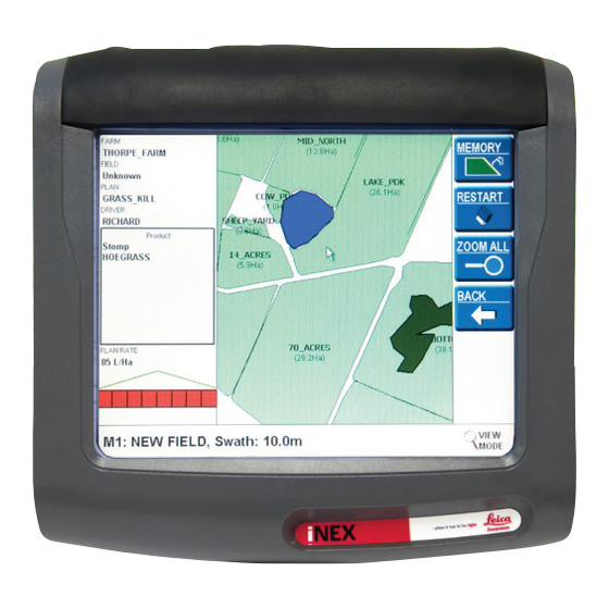
Page 20: Screen Layout
Screen Layout After starting the iNEX it will be ready for use when the main screen is displayed as shown. During normal operation the iNEX Display is divided into several distinct parts. These parts are described in the following pages. - Page 21 ON (red) or OFF (white). In the event that any section has an active AutoSPRAY override the section will be shown with a cross though it. Page 14 Rev 2 iNEX User Manual...
-
Page 22: Gps Status
3.3.6 AutoSPRAY Status The AutoSPRAY Status Button will only be shown if AutoSPRAY has been enabled on the iNEX. When it is displayed it will be shown in one of four colours. Green represents AutoSPRAY as ON and functioning normally; Orange when AutoSPRAY override is functioning;... -
Page 23: Status Bar
Status Messages are to be displayed can be configured in Display Setup. Note: The iNEX Display has a touch sensitive screen, which means that the system is operated by touching the buttons on the screen. The user should touch the button on the screen with only their finger to select the button. -
Page 24: Basic Menu Layout
Basic Menu Layout The iNEX is operated and configured by a menu system. The menus are accessed by touching the appropriate part of the screen. Touching any one of the menu buttons will either activate the function associated with the button or lead to a sub-menu. A sub-menu is similar to the main menu whereby touching the button may either activate a function or lead to a further sub-menu. -
Page 25: Creating A Basic Vehicle
It is particularly relevant as automatic control of treatment application is adopted. The iNEX can accurately model a self propelled vehicle or any implement which is towed by a vehicle. In order to perform these calculations it is imperative that the measurements of the vehicle and GPS antenna are accurately recorded. - Page 26 9. Repeat these steps for each equipment item that makes up the Rig. Note: See Appendix 15.1 Equipment Measurement Examples for examples of how to measure other vehicles such as Self Propelled Sprayer with front mounted Boom, etc. Page 19 Rev 2 iNEX User Manual...
- Page 27 5. Press when all Equipment items in the Rig have been selected. TICK Note: The iNEX will only allow a TRACTOR to be added as the first equipment item in a Rig while subsequent equipment items must be IMPLEMENTS. Page 20...
- Page 28 3.5.2.2 Configure Advanced Settings Depending on the options which have been purchased with the iNEX the Tank Size, Flow Controller or Steer Controller settings may be available and need to be configured. If the relevant setting button in the Rig is disabled then the option has not been enabled or is locked to a particular setting.
- Page 29 4. Press TICK. 3.5.3 Master & Section Switch Detection To determine when to record treatment the iNEX has a Master Switch and Section Switches. These switches can be triggered by touching the screen or sensing the state from external hardware.
- Page 30 To use the Sense Dipole option an AS310 is required. For more information see the iNEX Installation Manual. Flow Controller When the Flow Controller setting is used the system will detect the Master Switch Status from the selected flow controller.
- Page 31 AutoSPRAY Voltage port if connected. AutoSPRAY The system will automatically configure the Section Switches to AutoSPRAY when AutoSPRAY is enabled and turned ON. This will allow the iNEX to automatically control the state of the sections. Page 24 Rev 2...
-
Page 32: Treating A Field
Receiver Initialising, (Alert Icon) Too Few Satellites No Data Cable disconnected, (Blank Box) Receiver not powered View Mode In Field Menu, user can (Glasses) touch the screen to zoom in on an area Page 25 Rev 2 iNEX User Manual... -
Page 33: Starting A New Field
3.6.2 Starting A New Field When the iNEX is started it will load the last treatment used when the system was shut down. When starting a new field the current field should be cleared to ensure it is ready for the new information. - Page 34 This example demonstrates how to set a parallel line and follow the associated Guidance. The iNEX can be configured for several different types of Guidance. By default the system is setup to display Parallel and A+ Heading Guidance on the Guide menu. The following steps assume the defaults have not been changed.
- Page 35 Parallel and A+ Heading buttons if required. See section 4.2 Selecting Active Guidance Types for more information. Note: To ensure accuracy of the system, enter the vehicle measurements as outlined in section 3.5.1 Define Vehicle Offsets Page 28 Rev 2 iNEX User Manual...
-
Page 36: Guidance
4 Guidance Different Types Of Guidance Available A major feature of iNEX is the ability to provide guidance to the operator so that treatment can be applied to a field as accurately as possible. In order to treat an entire field the operator will want to ensure that no areas are missed and minimise overlapping areas. - Page 37 RePLAY RePLAY will provide guidance along the path of a previous treatment. After loading an archived treatment as a RePLAY file, guidance will be provided along the nearest previous path. Page 30 Rev 2 iNEX User Manual...
-
Page 38: Selecting Active Guidance Types
RED boarder. The selected Guidance for the other button is shown with a thick GREY boarder. Note: Any Guidance type which has not been enabled on the iNEX is shown in grey and cannot be selected. -
Page 39: Using Guidance
Note: A new Parallel guideline can be created by pressing the PARALLEL button when Parallel Guidance is active. Page 32 Rev 2 iNEX User Manual... - Page 40 Note: A new A+ Heading guideline can be created by pressing the A+ HEAD button when A+ Heading Guidance is active. The operator will be warned before the existing line is replaced. Page 33 Rev 2 iNEX User Manual...
- Page 41 Which treatment area is chosen to create the guideline can be configured by the operator. See 4.4.3 Defining the Adaptive Guidance Direction. Page 34 Rev 2 iNEX User Manual...
- Page 42 PIVOT Guidance. The Map Screen shows a red circle which passes though the A, B & C Points. The Virtual Road Window shows the path to be followed by the operator. Page 35 Rev 2 iNEX User Manual...
- Page 43 Note: The operator will be warned and prevented from defining a C point if the radius of the circle created by A, B & C points is too large or in a straight line. Page 36 Rev 2 iNEX User Manual...
- Page 44 Active Guidance Type (see section 4.2 Selecting Active Guidance Types). 1. From the Main menu press GUIDE. 2. Press OPTIONS. 3. Press LOAD. 4. Select the RePLAY File to load and press LOAD. Page 37 Rev 2 iNEX User Manual...
- Page 45 Note: If no path is displayed on the screen after activating RePLAY, check that the RePLAY path loaded is for the current vehicle location – no path will be displayed if the vehicle is too far from the path. Page 38 Rev 2 iNEX User Manual...
-
Page 46: Configuring Guidance Options
1. From the Main menu press SETUP. 2. Press MORE. 3. Press GUIDE OPTIONS. 4. Press the Guide Offset value button. 5. Enter the desired amount and press TICK. Page 39 Rev 2 iNEX User Manual... - Page 47 Left Only searches only to the left for a previous treatment swath. This setting is typically used when only travelling clockwise around a paddock and never changing direction. Page 40 Rev 2 iNEX User Manual...
- Page 48 4.4.4 Adjusting the Guideline for GPS Drift Depending on the specific hardware configuration for the iNEX from time to time it may be necessary to adjust a guideline to compensate for drift in the GPS position. This is particularly evident when using lower quality GPS receivers, returning to a field and using guidelines several hours after they were created.
-
Page 49: Save & Load Guidelines
Save & Load Guidelines 4.5.1 Saving a Guideline Parallel, A+ Heading, Pivot, and Contour guidelines can all be saved to the iNEX memory and easily transferred to another system or recalled at a later time. 1. From the Main menu press GUIDE. - Page 50 4.5.3 Renaming a Guideline Any guideline saved on the iNEX memory or a USB memory stick can easily be renamed when required from the Load Guideline screen. 1. From the Main menu press GUIDE. 2. Press OPTIONS. 3. Press LOAD.
- Page 51 TICK Note: If the iNEX Tab is selected when TRANSFER is pressed the guidelines will be copied to the USB Memory Sick. Note: If the USB Tab or mojoRTK Tab is selected when TRANSFER is pressed the guidelines will be copied to the iNEX.
-
Page 52: Field Memory
5 Field Memory Field Memory The iNEX has a temporary Field Memory which can store up to nine partially completed treatments. The system also has the ability to archive treatments from the temporary Field Memory to the permanent History. Fields saved to the History can be transferred to other systems, to the office PC or kept on the iNEX long term. - Page 53 1. From the Main menu press FIELD. 2. Press MEMORY. 3. Select the memory slot with the treatment to be cleared by pressing on the relevant square. 4. Press SELECT. 5. Press & TICK. RESTART Page 46 Rev 2 iNEX User Manual...
-
Page 54: Field History
5.2.1 Creating a Season To make sorting and managing archived fields easy the iNEX saves treatments within a seasonal structure. It is recommended that a new season is created with each new cropping season or on an annual basis. - Page 55 AutoFIELD will detect which field the treatment belongs to. Note: When Advanced Data Records is enabled the field will be stored under the Client & Farm selected in Current Job when the treatment was started. Page 48 Rev 2 iNEX User Manual...
- Page 56 EDIT 5. Press UN-ARCHIVE FIELD. Note: When a treatment is Un-Archived it is removed from the Field History. If this treatment is then cleared from the Field Memory it will be permanently deleted. Page 49 Rev 2 iNEX User Manual...
- Page 57 All Archived fields can be exported from the system and can be transferred to the office or another iNEX. 1. Insert a USB memory stick in the USB port on the side of the iNEX. 2. From the Main menu press SETUP.
- Page 58 DELETE. 6. Select if a summary is to be kept or not by pressing until the desired YES/NO answer is displayed then press OK. 7. Press again to confirm deletion of the season. Page 51 Rev 2 iNEX User Manual...
-
Page 59: Advanced Data Records
6 Advanced Data Records The Advanced Data Records option enhances the power of the iNEX by automatically managing treatment data. It does this by recognising the current field the vehicle is in via the AutoFIELD feature. This can then be used to check plans loaded in the Tank Manger are carried out in the correct location. -
Page 60: Selecting A Client & Farm
Selecting a Client & Farm When using the iNEX with multiple Clients or Farms it is important that these be selected as the Current Job before commencing any other work. 1. From the Main menu press SETUP. 2. Press CURRENT JOB. - Page 61 When the field is archived, if it has not been done inside a recognised boundary, the iNEX will ask if a boundary is to be created.
- Page 62 Background Map. 6.3.2 Using Boundaries to Manage Treatments When field boundaries have been created, the iNEX will use these to determine which field the vehicle is currently in and in turn, automatically load the appropriate Memory slot. When loading the appropriate Memory...
-
Page 63: Using The Tank Manager
6.4.1 Recording Products Applied The products which are being applied should be entered in the iNEX before starting the treatment. If done when filling the tank the system calculates the quantities of each product required. - Page 64 PRODUCT 16. Product quantities, rates, and batch details can be changed by selecting the product and pressing EDIT. Products can be removed from the list by selecting the product and pressing REMOVE. Page 57 Rev 2 iNEX User Manual...
- Page 65 ACCEPT to the Map Screen and begin work. The tank volume recorded on the iNEX will run down at a similar rate to the real tank volume on the vehicle. When the tank is completely empty it will also need to be refilled. If refilling the tank with the same product mix or similar there is a Fast Fill process for this.
- Page 66 The Units in Tank value refers to the units that are normally used to describe the application rate of the product. 5. Press when all required values have been entered. ACCEPT Page 59 Rev 2 iNEX User Manual...
- Page 67 6.4.3 Adding a Product Batch Product quantities in store and batch numbers can be tracked if required by the iNEX. When product quantities are recorded the system will automatically reduce the total amount recorded in the system for a given product when the field is archived.
-
Page 68: Recording Weather Details
Recording Weather Details When the Advanced Data Recording option has been purchased weather records can be entered on the iNEX while out in the field. 1. From the Main Menu press RECORDS. 2. Press WEATHER. 3. Press NEW. 4. Press WIND. Enter wind speed value and the wind direction and press TICK. -
Page 69: Using Flags
PlanIT. 1. From the Main Menu press RECORDS. 2. Press FLAGS. 3. Press one of the four shapes to mark the current point with that shape flag. Page 62 Rev 2 iNEX User Manual... -
Page 70: Driver Security
OFF. If required this feature can be setup to allow operators to log into the iNEX. Each driver can be preconfigured for one of three security levels to prevent unauthorised access to critical settings or to prevent an operator deleting information. - Page 71 Low is typically used for temporary operators who have little knowledge of the iNEX. When Low is selected the operator will not be able to change operational settings such as vehicle setup, AutoSPRAY configuration, etc.
-
Page 72: Customising The System
7 Customising the System Enabling New Options The iNEX can be purchased as an entry level product and as new features are required by the operator they can be added by entering a new feature unlock code (password). On the first startup of the iNEX the operator will be presented with the password entry screen. -
Page 73: Setting The Gps Source Options
Setting the GPS Source Options Depending on the options purchased the iNEX can work with many different sources of GPS. By default the system will be configured to work with a GPS receiver supplying NMEA information via a serial connection at 19200 baud. -
Page 74: Selecting The Language
Selecting the Language The iNEX has the capability to operate in a number of different languages. If the system has been set to operate in an unknown language these steps can be followed without being able to read the on-screen language. -
Page 75: Configuring The Display
3. Also in the View menu the operator can choose to Zoom on the map by touching the appropriate button. Pressing the Zoom button will cause the map to zoom to a level where all of the current treatment is visible. Page 68 Rev 2 iNEX User Manual... - Page 76 SETUP. 7.4.3 Setting Up a Map Grid The iNEX can be configured to display a grid along with the treatment on the Map Screen. The grid size can be defined by the operator to help provide a perception of size and scale for the displayed treatment.
- Page 77 7.4.4 Selecting Measurement & Position Units The iNEX can be customised to display Metric or Imperial measurement units and also Easting & Northing or Latitude & Longitude position units depending on the operator's requirements. 1. From the Main menu press SETUP.
-
Page 78: Configuring Remote Buttons
Configuring Remote Buttons The iNEX has the capacity for five remote buttons to be configured by the operator. The first four, labelled button 1, 2 ,3 & 4 are on top of the Display. The fifth remote button, labelled Remote Input can be connected to detect any momentary switch. -
Page 79: Setting The Sound Volume & Options
Setting the Sound Volume & Options The iNEX has a number of alarms and warnings which will make a sound through the onboard speaker. The options enabled will determine which alarms or warnings can be configured. 1. From the Main menu press SETUP. -
Page 80: Autosteer
Each AutoSTEER controller has specific tuning requirements and the specific instructions supplied with the controller should be read. To access the tuning screen press and hold down the AutoSTEER Status button for three seconds. Page 73 Rev 2 iNEX User Manual... -
Page 81: Using Autosteer
AutoSTEER and the vehicle will no longer steer automatically. If an error occurs that is related to AutoSTEER then the AutoSTEER Status button will be GREY and will do nothing when pressed. Page 74 Rev 2 iNEX User Manual... - Page 82 • Press a Remote Button configured to engage/disengage steering (see section 7.5 Configuring Remote Buttons. Note: Read the manual supplied with the AutoSTEER controller to determine which methods are available to engage and disengage steering. Page 75 Rev 2 iNEX User Manual...
-
Page 83: Virtual Wrench
9 Virtual Wrench™ Virtual Wrench is an optional feature which is enabled when the iNEX is connected to a mojoRTK console and the required mojoRTK unlock code has been entered (see 7.1 Enabling New Options). Using the mobile phone network Virtual Wrench can be used by the operator to request support or to perform remote software upgrades. -
Page 84: Requesting Remote Support
9.1.1 Disconnecting from Virtual Wrench The iNEX can continue to be used while connected to the Virtual Wrench service. While the system is connected a wrench symbol will be displayed on the AutoSTEER Status button The system will automatically disconnect from Virtual Wrench when it is turned OFF, alternatively the operator may manually disconnect. -
Page 85: Upgrading Software Remotely
Upgrading Software Remotely Virtual Wrench offers an easy approach to upgrading the software on the iNEX to the very latest available. Upon request the system can download and automatically install the latest software. 1. Press the GPS Status button 2. Press OPTIONS. -
Page 86: Autospray
ON or OFF when going over a previously treated area by automatically controlling the state of the sections. 10.1 Setting Up AutoSPRAY Once AutoSPRAY has been unlocked on the iNEX the feature can be switched ON and OFF as necessary. 1. From the Main Menu press SETUP. -
Page 87: Calibrating Autospray
Ensure that there is enough distance before crossing over the marked line for the boom trailer to straighten up behind the tractor. Measure the distance from the rope to where the sprayer actually reacted. Page 80 Rev 2 iNEX User Manual... - Page 88 The section takes too long to Increase ON Latency turn ON and is causing a value missed area The section turns ON too early Decrease ON Latency and is causing overlap value Page 81 Rev 2 iNEX User Manual...
- Page 89 It is effectively the percent of miss that the system will tolerate. If the value is increased, the system will not turn the valves on when traversing over a small missed area such as a line between two spray swaths. Page 82 Rev 2 iNEX User Manual...
- Page 90 10.2.3 Translation The translation feature allows the iNEX to reconfigure the section voltage output to different pins on the AutoSPRAY voltage interface connector. This may be necessary if some or all of the sections turn off in the wrong order when AutoSPRAY automatically turns sections ON or OFF over a treated area.
-
Page 91: Using Autospray
AutoSPRAY Override function. Provided the system is properly configured for the connected flow controller, switching to manual control turns automatic control of the sections off, and the iNEX simply detects the sections which are manually being used on the controller. - Page 92 RIGHT to be overridden from left to right. 4. Press the arrow to select sections LEFT to be overridden from right to left. 5. Press to return all sections to RESET AutoSPRAY control. Page 85 Rev 2 iNEX User Manual...
-
Page 93: Fieldnet
FieldNET operates with up to four vehicles operating in the same paddock and transferring their information to all other vehicles in the paddock. The real-time mapping functionality in the iNEX is transmitted to the other vehicles with FieldNET so all vehicles will be able to see exactly which areas have been treated, regardless of the vehicle that applied the product. -
Page 94: Configuring The System For Fieldnet
FieldNET radios is experienced. See appendix 15.2 Setting the FieldNET Radio Group ID. After connecting the FieldNET radio and enabling the FieldNET option the next step is to configure the settings in the iNEX. 1. From the Main Menu press SETUP. 2. Press MORE. -
Page 95: Using Fieldnet
Guide The treatment received from the selected vehicle will be treated as if it is the same as the current treatment and therefore all of the normal features of the iNEX such as Guidance and AutoSPRAY are available. Display The treatment received from the selected vehicle will be in a separate layer under the current treatment. - Page 96 3. Select the vehicle from the list to set the Link Type and press OPTIONS. 4. Repeatedly press until the LINK TYPE desired Link Type is displayed. 5. Press BACK. Note that the Link Type for the selected vehicle has changed. Page 89 Rev 2 iNEX User Manual...
- Page 97 If the antenna is not flashing then the vehicle represented by the box is out of range or switched OFF. Page 90 Rev 2 iNEX User Manual...
-
Page 98: System Maintenance
Launcher mode provides access to a menu of system maintenance tools, such as calibrating the touch screen or performing a software update. 1. To start into Launcher mode the iNEX must first be OFF. 2. When turning ON press and hold the Power button until two short beeps are heard. -
Page 99: Upgrading Software
2. Press SOFTWARE. 3. Press UPGRADE. 12.3 Downgrading Software When the iNEX is updated a backup of the current software will be created to allow the system to be restored to the previous version if required. When the previous version is restored any settings or treatments recorded since the upgrade will be lost. -
Page 100: Calibrating The Touch Screen
A forced shutdown will make unresponsive systems turn off. In most cases when the iNEX is then turned on again the problem will be resolved. If a forced shutdown is often required the system may need servicing. - Page 101 12.5.1 Force Shutdown If the iNEX becomes unresponsive and cannot be turned off, then a forced shutdown may be required. A shutdown can be forced by removing power to the Display for 30 seconds. Press and hold the Power button for five seconds until three long beeps are heard.
-
Page 102: Soft Reset
REPAIR DATABASE. 12.5.4 Soft Reset Running Soft Reset will cause the iNEX to clear all temporary files and all treatments currently in the Field Memory. Some data will be lost. 1. Start the iNEX into Launcher mode (see 12.1 Starting Up in Launcher Mode). -
Page 103: Hard Reset
12.5.5 Hard Reset A Hard Reset should be used as a last resort to recover the iNEX, as running Hard Reset will cause the system to clear all data, returning it to factory default condition. 1. Start the iNEX into Launcher mode (see 12.1 Starting Up in Launcher... -
Page 104: Safety
Do not disassemble or alter the iNEX. Doing so may result in failure, electric shock, or fire. Do not subject the iNEX to high levels of moisture. Use the iNEX only in vehicles with a 12-volt negative ground system. Follow recommended safety precautions and operating procedures at all times. -
Page 105: Intended Use
Permitted use • The iNEX is intended for agricultural and forestry use only. • The iNEX is only intended to be fitted to agricultural vehicles. It is not permitted to install this product in any other vehicles. • Data communication with external appliances. -
Page 106: Limits Of Use
Danger Local safety authorities and safety experts must be contacted before working in hazardous areas, or in close proximity to electrical installations or similar situations by the person in charge of the product. Page 99 Rev 2 iNEX User Manual... -
Page 107: Responsibilities
• To be familiar with local regulations relating to safety and accident prevention. • To inform Leica Geosystems immediately if the product and the application becomes unsafe. • To ensure that the national laws, regulations and conditions for the operation of radio transmitters are respected. -
Page 108: Hazards Of Use
• Precautions: Always ensure that the working site is adequately secured. Adhere to the regulations governing safety and accident prevention and road traffic. • Only Leica Geosystems authorized service workshops are entitled to repair these products. Page 101 Rev 2... - Page 109 • Avoid subjecting the product to mechanical stress. Warning • Incorrect fastening of the iNEX and cabling to vehicles or transporters poses the risk of the equipment being broken by mechanical influence, vibration. This may result in accident and injury.
- Page 110 - antenna. Warning • If the product is improperly disposed of, the following can happen: If polymer parts are burnt, poisonous gases are produced which may impair health. Page 103 Rev 2 iNEX User Manual...
- Page 111 Always prevent access to the product by unauthorized personnel. Product specific treatment and waste management information can be downloaded from the Leica Geosystems home page at http://www.leica-geosystems.com/treatment or received from your Leica Geosystems dealer. Page 104...
-
Page 112: Electromagnetic Compatibility Emc
Electromagnetic radiation can cause disturbances in other equipment. • Although the product meets the strict regulations and standards which are in force in this respect, Leica Geosystems cannot completely exclude the possibility that other equipment may be disturbed. Caution •... - Page 113 • Precautions: While the product is in use, connecting cables, for example product to external battery, product to external devices, must be connected at both ends. Page 106 Rev 2 iNEX User Manual...
-
Page 114: International Limited Warranty, Software Licence Agreement
Leica Geosystems. Such software is protected by copyright and other laws and its use is defined and regulated by the Leica Geosystems Software Licence Agreement, which covers aspects such as, but not limited to, Scope of the Licence, Warranty, Intellectual Property Rights, Limitation of Liability, Exclusion of other Assurances, Governing Law and Place of Jurisdiction. - Page 115 You must not install or use the software unless you have read and accepted the terms and conditions of the Leica Geosystems Software Licence Agreement. Installation or use of the software or any part thereof, is deemed to be an acceptance of all the terms and conditions of such licence agreement.
-
Page 116: Appendix
• Tow Between Tank or Air Cart • Trailer with Front Pivoting Axle The main principal when entering equipment into the iNEX is that measurements are intended to define the antenna point in relation to the equipments pivoting point, such as a fixed axle, and the hitch or flow point. - Page 117 If GPS antenna is left of the centreline then enter value as a negative. Icon Measurement Value 1. Back of cabin to axle centreline. 2. Vehicle body width. 3. Axle centreline to front of vehicle. Page 110 Rev 2 iNEX User Manual...
- Page 118 If GPS antenna is left of the centreline then enter value as a negative. Icon Measurement Value 1. Back of cabin to track centreline. 2. Vehicle body width. 3. Track centreline to front of vehicle. Page 111 Rev 2 iNEX User Manual...
- Page 119 3. Front axle centreline to front of vehicle. Equipment 2 – Rear Half 1. Rear axle centreline to back of tractor. 2. Vehicle body width. Same as value 2 above. 3. Rear axle centreline to articulation point. Page 112 Rev 2 iNEX User Manual...
- Page 120 If GPS antenna is left of the centreline then enter value as a negative. Icon Measurement Value 1. Back of vehicle to rear axle centreline. 2. Vehicle body width. 3. Rear axle centreline to front of vehicle. Page 113 Rev 2 iNEX User Manual...
- Page 121 Icon Measurement Value 1. Flow point to rear axle centreline. Same value as Physical Measurement 1 above. 2. Vehicle body width. 3. Rear axle centreline to front of vehicle. Page 114 Rev 2 iNEX User Manual...
- Page 122 If GPS antenna is left of the centreline then enter value as a negative. Icon Measurement Value 1. Back of vehicle to rear axle centreline. 2. Vehicle body width. 3. Rear axle centreline to flow point. Page 115 Rev 2 iNEX User Manual...
- Page 123 Icon Measurement Value 1. Flow point to half way between steered wheels. Same value as Physical Measurement 1 above. 2. Vehicle body width. 3. Half way between steered wheels to front of vehicle. Page 116 Rev 2 iNEX User Manual...
- Page 124 If GPS antenna is left of the cutter bar centreline then enter value as a negative. Icon Measurement Value 1. Back of vehicle to front axle centreline. 2. Vehicle body width. 3. Front axle centreline to front of vehicle. Page 117 Rev 2 iNEX User Manual...
- Page 125 2. Axle centreline to hitch point. Icon Measurement Value 1. Flow point to axle centreline. Same value as Physical Measurement 1 above. 2. Trailer body width. 3. Axle centreline to front of trailer. Page 118 Rev 2 iNEX User Manual...
- Page 126 Same value as Physical Measurement 1 above. 2. Trailer body width. 3. Half way between tractor rear wheels & boom axle centreline to hitch point. Same value as Physical Measurement 2 above. Page 119 Rev 2 iNEX User Manual...
- Page 127 1. Rear hitch point to axle centreline. 2. Axle centreline to front hitch point. Icon Measurement Value 1. Back of trailer to axle centreline. 2. Trailer body width. 3. Axle centreline to front of trailer. Page 120 Rev 2 iNEX User Manual...
- Page 128 Equipment 2 – Rear Half 1. Rear axle centreline to back of tractor. 2. Trailer Body width. Same as value 2 above. 3. Rear axle centreline to front axle centreline. Page 121 Rev 2 iNEX User Manual...
-
Page 129: Setting The Fieldnet Radio Group Id
If changing the Group ID on one radio then all radios that are intended to work together must be changed to match. 1. Start the iNEX into Launcher mode (see 12.1 Starting Up in Launcher Mode). -
Page 130: Gps Receiver Settings
Note: Receive baud rate can be configured on the GPS Setup screen (see section 7.2 Setting the GPS Source Options). 15.3.2 NMEA-2000 (CANbus) Messages Required: • POS @ 5Hz Baud Rate: • 250kbs Note: J1939 Velocity (VEL) message must be turned off. Page 123 Rev 2 iNEX User Manual... -
Page 131: Connection Pin Assignments
Transmit Data (TxD) Data Terminal Ready (DTR) Data Drain (GND) Data Set Ready (DSR) Request to Send (RTS) Clear to Send (CTS) Port B Function Receive Data (RxD) Transmit Data (TxD) Data Drain (GND) Page 124 Rev 2 iNEX User Manual... -
Page 132: Power Input
CANbus Function CAN A Low CAN A Drain CAN A High Power Input Function Battery Negative Vehicle Ignition Sense Input Battery Positive For AS310 High Current Battery Positive Page 125 Rev 2 iNEX User Manual...
Need help?
Do you have a question about the iNEX and is the answer not in the manual?
Questions and answers