Table of Contents
Advertisement
Quick Links
Advertisement
Table of Contents

Related Manuals for Leica INEX 1-1296


Summary of Contents for Leica INEX 1-1296
- Page 1 Mapping & Guidance Display Installation Manual...
- Page 2 By use of this system you agree that Leica Geosystems is not liable or responsible for any damage whatsoever to the vehicle, any property, personal injuries, or death that may result from the use or abuse of this system.
- Page 3 Leica iNEX Installation Manual Written for Leica iNEX Mapping & Guidance Display Part number: 1-1296 Revision: Publication Date: February 2009 © Copyright 2009 Leica Geosystems Pty Ltd. All rights reserved. Acknowledgements ® Windows XP is registered to Microsoft Corp. Other products and trademarks mentioned in this manual are the property of their registered owners.
- Page 4 For Products forming part of a fixed installation, such place of performance shall be the site of such installation and Leica Geosystems shall have the right to charge for additional costs for such services under warranty if the site of the Product is other than where the Product was originally installed or shipped.
- Page 5 Switzerland, excluding all conflict of laws principles and excluding the United Nations Convention on the International Sale of Goods dated 11 April 1980. The ordinary courts at the Leica Geosystems registered office in Balgach, Switzerland shall be competent. Leica Geosystems shall, at its sole discretion, also be entitled to take legal action in the competent courts at the Customer’s place of business or domicile.
- Page 6 iNEX Installation Manual Page 5 Rev 1...
-
Page 7: Table Of Contents
Table Of Contents About The Leica iNEX ................8 Product Description ................8 Precautions And Safety Measures............8 Leica iNEX Components................9 iNEX Display..................9 iNEX Vehicle Cable................10 Power Cable..................11 AS310 (Optional Component) ............. 11 System Installation ................. 12 Before Installation................ - Page 8 iNEX Installation Manual Page 7 Rev 1...
-
Page 9: About The Leica Inex
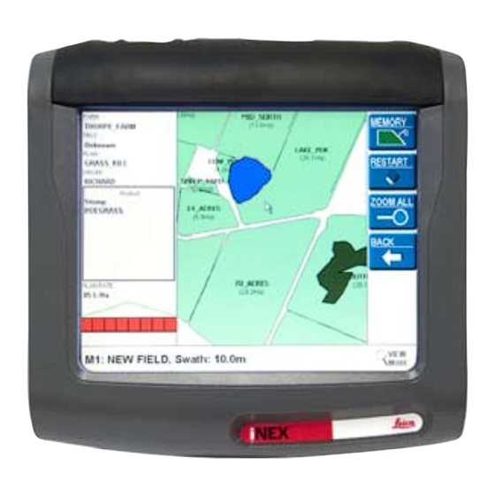
1 About The Leica iNEX 1.1 Product Description The Leica iNEX is a GPS-based guidance system with the capability to interface to a number of different 3rd party components such as GPS receivers, rate controllers and steer controllers. The Leica iNEX is a robust single body computer system manufactured specifically for use in agriculture. -
Page 10: Leica Inex Components
2 Leica iNEX Components 2.1 iNEX Display a. Power button b. Brightness down/up c. Remote buttons 1 to 4 d. Speaker e. RAM mount f. USB port g. Touch screen h. Display connector (male) iNEX Description Power Button RAM Mount Press to turn iNEX on and off. -
Page 11: Inex Vehicle Cable
2.2 iNEX Vehicle Cable a. Display connector (female) b. Port A (blue) c. Port B (yellow) d. Remote Master (brown) e. CANbus (white) f. Remote Input (white) g. Power input connector h. Port C Vehicle Cable Description Display Connector (female) Connects to the iNEX Display. -
Page 12: Power Cable
2.3 Power Cable a. Power connector b. Red wire (12-volt positive) c. Black wire (negative ground) Power Cable Description Power Connector Black Wire (negative ground) Supplies 12-volt power to the Connects to the vehicle's earth. iNEX via the Power Input connector on the Vehicle cable. -
Page 13: System Installation
Leica Geosystems is not liable for any damage, faults or risks related to installation or to the iNEX or your vehicle due to installation. Leica Geosystems declines all responsibility for any incorrect information in the iNEX Installation Manual. -
Page 14: Installing The Inex Display
3.2 Installing The iNEX Display 1. Read all instructions before attempting installation. 2. Attach the RAM mount arm, and separate RAM mount ball to the RAM mount on the iNEX Display. 3. Pick a suitable location to mount the Display by holding it up in place while checking for visibility out of the vehicle. -
Page 15: Installing The Power Cable
3.3 Installing The Power Cable The Power Cable should be connected to a clean 12-volt power system; however the iNEX will operate between 9 and 16 volts DC and as such will tolerate normal fluctuations found in a typical vehicle power system. 1. -
Page 16: Installing The Inex Vehicle Cable
3.4 Installing The iNEX Vehicle Cable 1. Connect the Display connector on the vehicle cable to the iNEX Display. The connectors may need to be twisted until the locating tabs in the connectors align. Push the connectors firmly together while twisting the locking ring. 2. -
Page 17: Connecting Remote Master
3.5 Connecting Remote Master The iNEX is designed to sense 12-volts DC from a master switch, which when configured will activate the treatment recording function on the iNEX. It is recommended that the Remote Master is connected to an existing master switch in the vehicle, however there are many options including 12-volts DC from a master valve, an implement switch or a separate toggle switch. -
Page 18: Connecting The Optional As310
3.7 Connecting The Optional AS310 The AS310 is required for some installations where automatic section shut-off is being used. The AS310 converts signals from the iNEX to output signals which can then be connected to 3rd party rate controllers and other section control equipment. 1. -
Page 19: Appendix
4 Appendix 4.1 Connection Pin Assignments Port A Function Receive Data (RxD) Transmit Data (TxD) Data Terminal Ready (DTR) Data Drain (GND) Data Set Ready (DSR) Request to Send (RTS) Clear to Send (CTS) Port B Function Receive Data (RxD) Transmit Data (TxD) Data Drain (GND) iNEX Installation Manual... - Page 20 CANbus Function CAN A Low CAN A Drain CAN A High Power Input Function Battery Negative Vehicle Ignition Sense Input Battery Positive For AS310 High Current Battery Positive iNEX Installation Manual Page 19 Rev 1...
- Page 21 AS310 Voltage Port Function Section 1 Section 2 Section 3 Section 4 Section 5 Section 6 Section 7 Section 8 Master Switch Input / Dipole ON Input Section 9 Section 10 Section 11 Section 12 Section 13 / Dipole OFF input iNEX Installation Manual Page 20 Rev 1...
Need help?
Do you have a question about the INEX 1-1296 and is the answer not in the manual?
Questions and answers