
Subscribe to Our Youtube Channel
Related Manuals for Polycom Collaboration Server (RMX) 2000


Summary of Contents for Polycom Collaboration Server (RMX) 2000
- Page 1 [Type the document title] Version June 2013 DOC2728A Polycom® RealPresence® Collaboration Server (RMX) 2000 Hardware Guide Polycom Document Title...
- Page 2 Every effort has been made to ensure that the information in this manual is accurate. Polycom, Inc., is not responsible for printing or clerical errors. Information in this document is subject to change without notice.
- Page 3 2. This device must accept any interference received, including interference that may cause undesired operation. Modifications: Any modifications made to this device that are not approved by Polycom, Inc. may void the authority granted to the user by the FCC to operate this equipment.
- Page 4 Härmed intygar Polycom (UK) Ltd att denna Polycom RMX står I överensstämmelse med de väsentliga egenskapskrav och övriga relevanta bestämmelser som framgår av direktiv 1999/5/EG. A full copy of the Declaration of Conformity can be obtained from Polycom Ltd, 270 Bath Road, Slough, Berkshire, SL1 4DX, UK. China CCC EMC statement 警告...
- Page 5 If trouble is experienced with this equipment, for repair or warranty information, please contact Polycom Inc in the U.S.A. 1-888- 248-8294. If the equipment is causing harm to the telephone network, the telephone company may request that you disconnect the equipment until the problem is resolved.
-
Page 7: Table Of Contents
Operating Mode Selection During Startup / Restart ........1-21 System Information Changes ................1-21 RealPresence Collaboration Server (RMX) 2000 LEDs ........... 1-24 RealPresence Collaboration Server (RMX) 2000 Front Panel LEDs ...... 1-24 RealPresence Collaboration Server (RMX) 2000 Rear Panel LEDs ......1-25 RTM IP Card ......................1-25 RTM ISDN Card .................... - Page 8 Polycom RealPresence Collaboration Server (RMX) 2000 Hardware Guide Using the All Metal Ejector Lever ..............1-29 Using the Modified PMC Compatible Ejector Lever ........1-30 Replacing the CNTL Module ..................1-30 Replacing the Power Supply Module ................1-31 Replacing the Fan Drawer ...................1-32 Replacing a Faulty MPM/MPM+/MPMx Card ............1-33 Removing the MPM/MPM+/MPMx Card from the MCU ......1-33...
-
Page 9: Hardware Description
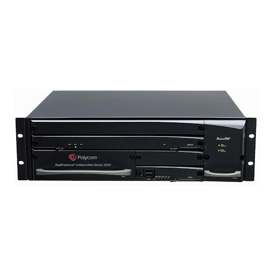
This Hardware Guide provides information on the RealPresence Collaboration Server (RMX) 2000 and its components. This system utilizes a modular “universal slot” platform, whose components are designed for high performance, capacity and reliance. ® ® The product names, Polycom RealPresence Collaboration Server 2000 ® and RMX 2000 are used interchangeably throughout this document. -
Page 10: Realpresence Collaboration Server (Rmx) 2000 Specifications
Weight Up to 16.5 Kg (36.38 lbs). Media Protocols Audio G.711a/u, G.722, G.722.1C, G.722.1, G.723.1, G.719 G.729A, Polycom Siren™ 14, Siren 22 (in mono or stereo) and Siren LPR. Video H.261, H.263, H.264, H.264 High Profile Network Interfaces IP, ISDN, PSTN and LAN H.323, SIP, ISDN, PSTN, VoIP, and LAN... -
Page 11: Realpresence Collaboration Server (Rmx) 2000 System Capacities
Chapter 1-Hardware Description RealPresence Collaboration Server (RMX) 2000 System Capacities Conferencing Capacities The following table summarizes the different conferencing capacities. Table 1-2 System Functions and Capacities RMX 2000 System Functions MPM Mode MPM+ Mode MPMx Mode Maximum number of Video participants in a... -
Page 12: Resource Capacities
RealPresence Collaboration Server (RMX) 2000 Hardware Guide Table 1-2 System Functions and Capacities RMX 2000 System Functions MPM Mode MPM+ Mode MPMx Mode Maximum number of Users Maximum number of Gateway Profiles Maximum number of Reservations (internal 2000 2000 2000... -
Page 13: Safety Requirements
Decide on a suitable location for the equipment rack that will hold the RMX 2000 unit. It should be situated in a clean, dust-free area that is well ventilated. Avoid areas where heat, electrical noise and electromagnetic fields are generated. You will also need it placed near a grounded power outlet. Polycom, Inc. -
Page 14: Installation Precautions
RealPresence Collaboration Server (RMX) 2000 Hardware Guide • Ensure that the leveling jacks on the bottom of the rack are fully extended to the floor with the full weight of the rack resting on them. • In a single rack installation, stabilizers should be attached to the rack. -
Page 15: Installing The Rtm Isdn Card On The Realpresence Collaboration Server (Rmx) 2000
Note: rail runner end views Right rail runner (two See Figure 1-1 types available: with or without rail runner clip) Note: The rail runner clip is designed to attach and clip onto the chassis runner frame. Polycom, Inc. -
Page 16: Telescopic Rail Runner Assembly
RealPresence Collaboration Server (RMX) 2000 Hardware Guide Table 1-5 Rail Runners Kit Contents Item Item Part/Kit no. Item Item Sample Quantity Rack spacer Rack spacer Front & Rear assembly kit Flat head screw - M5*10mm Rail runner assembly Flat head screw -... - Page 17 (item no. 4) as shown in the following figure: RMX 2000 rack assembly view RMX 2000 rack assembly view without rail runner clip with rail runner clip Figure 1-2 Detail of Front Rack Spacer Assembly (left rail runner is shown here) for all RMX types Polycom, Inc.
- Page 18 RealPresence Collaboration Server (RMX) 2000 Hardware Guide • On the RMX1500/4000 the center hole on the Rack Spacer must be left clear as it is required for fixing the RMX to the rack post. See Figure 1-2. • On the RMX 2000 the top hole on the Rack Spacer must be left clear as it is required for fixing the RMX to the rack post.
-
Page 19: Other Rack Installation Options
— Install the shelf, supplied by the rack manufacturer, in the rack. — Mount the RMX on the shelf. — Fasten the RMX to the rack with screws through the four holes in the RMX’s front mounting brackets. 1-11 Polycom, Inc. -
Page 20: Connecting Cables To The Realpresence Collaboration Server (Rmx)
RealPresence Collaboration Server (RMX) 2000 Hardware Guide Connecting Cables to the RealPresence Collaboration Server (RMX) 2000 Do not remove the protective caps from LAN1, LAN3 and ShMG ports. Connect the following cables to the back panel: • Required. Power cable •... -
Page 21: Realpresence Collaboration Server (Rmx) 2000 Components
On the RMX 2000 components are located on both the front and rear of the MCU as listed in Table 1-6, "RMX 2000 Component Description". For more information see the descriptions of the "RealPresence Collaboration Server (RMX) 2000 Front Panel” on page 1-13 and "RealPresence... - Page 22 RealPresence Collaboration Server (RMX) 2000 Hardware Guide Table 1-6 RMX 2000 Component Description (Continued) Component Description Multi Processor Module The MPM cards perform the various RTP, audio and video processing (MPM) Card functions on the RMX 2000. MPM cards are based on the ATCA standard, with a card manager (CM) and up to 26 720MHz TI DSP’s.
-
Page 23: Realpresence Collaboration Server (Rmx) 2000 Rear Panel
Chapter 1-Hardware Description RealPresence Collaboration Server (RMX) 2000 Rear Panel The RMX 2000 rear panel contains the RTM IP card and optionally, the RTM LAN and RTM ISDN card. The RTM IP card must be located on the bottom slot in the rear of the RMX 2000. -
Page 24: Rtm Isdn
RealPresence Collaboration Server (RMX) 2000 Hardware Guide Table 1-7 RMX 2000 Rear Panel - RTM IP Component Description (Continued) Item Description LAN 3 For Remote Access only using the Alternate Management Network. For more information, see the RealPresence Collaboration Server (RMX) 1500/2000/ 4000 Administrators Guide Administrator’s Guide, Appendix G: "Configuring... -
Page 25: Isdn/Pstn Clock Source
RMX 2000. The LAN 1 and LAN 2 ports on the RTM LAN can be used for Media Redundancy. For more information, see Polycom® RealPresence® Collaboration Server 1500, 2000, 4000 Administrator’s Guide, "LAN Redundancy” on page 16-37 "Multiple Network Services”... -
Page 26: Cables Connected To The Rtm Ip, Rtm Lan And Rtm Isdn Cards
— Optional. Connect the LAN cable to LAN 1. With Multiple networks and LAN redundancy configurations, ports LAN 1 and LAN 2 can be used. For more information, see Polycom® RealPresence® Collaboration Server 1500, 2000, 4000 , "LAN Redundancy” on page 16-37 "Multiple Network Services”... -
Page 27: Mpm/Mpm+ And Mpmx Media Cards
Table 1-9 summarizes the resource capacities per line rate per card type in VSW Conferencing Mode. Table 1-9 MPMx, MPM+ and MPM Resource Capacity per Line Rate in VSW Maximum Possible Resources Per Card Resource Type MPM+ MPMx VSW 2Mbps VSW 4Mbps VSW 6Mbps Audio only (VoIP) 1-19 Polycom, Inc. -
Page 28: Mpm+ Resource Capacities Per Card Type Assembly
RealPresence Collaboration Server (RMX) 2000 Hardware Guide MPM+ Resource Capacities per Card Type Assembly The MPM+ card offers increased resource capacities and capabilities. Three MPM+ card assemblies are available: MPM+ 80, MPM+ 40 and MPM+ 20 offering various resource capacities for CP conferences. -
Page 29: Mpmx, Mpm+ And Mpm Modes
After Next Restart None MPM+ None MPM+ MPMx MPM and MPMx MPMx Only MPMx MPM+ and MPMx Only MPM+ MPMx MPMx None MPM+ None MPM+ MPM and MPM+ MPM+ Only MPM+ MPM+ MPM+ and MPM+ Only MPMx MPMx MPMx 1-21 Polycom, Inc. - Page 30 RealPresence Collaboration Server (RMX) 2000 Hardware Guide Table 1-12 RMX Card Configuration Mode After Next Restart Current Operating Media Cards Card(s) Card(s) Operating Mode Mode Installed Supported Disabled After Next Restart None MPM+ MPM Only MPM+ MPM+ MPM and MPM+...
- Page 31 MPM+ card is enabled. • The inserted MPMx card is disabled. After Reset • The Card Configuration Mode is MPMx. • The inserted MPMx card is enabled. • The remaining MPM+ card (if not removed) is disabled. 1-23 Polycom, Inc.
-
Page 32: Realpresence Collaboration Server (Rmx) 2000 Leds
LEDs reflect the state of the components. The LEDs on the rear panel indicate the state of the external connections and the status of the RTM IP card. RealPresence Collaboration Server (RMX) 2000 Front Panel LEDs The following items appear on the RMX 2000 front panel: Table 1-13 RMX 2000 Front Panel LED’s... -
Page 33: Realpresence Collaboration Server (Rmx) 2000 Rear Panel Leds
MPM/MPM+/ MPMx’s cards HS LED. OFF - Normal ON - CPU may be removed. RealPresence Collaboration Server (RMX) 2000 Rear Panel LEDs RTM IP Card The following LEDs appear on the RTM IP card: Table 1-14... -
Page 34: Rtm Isdn Card
RealPresence Collaboration Server (RMX) 2000 Hardware Guide Table 1-14 RMX 2000 RTM IP LEDs (Continued) Component LED Color Description Name SLOT (1-4) 1Gb (1-4) Amber ON with a 1Gb online connection, flickers with LEDs Packet activity. LNK (1-4) Green ON with an active network connection, flickers with Packet activity. -
Page 35: Rtm Lan Card
Packet activity. HS LED Blue OFF - Normal. Flashes - During the startup of a media card and control unit. Also flashes when the RTM LAN card is powered down. ON - RTM LAN card may be removed. 1-27 Polycom, Inc. -
Page 36: Rmx Chassis Types
RealPresence Collaboration Server (RMX) 2000 Hardware Guide RMX Chassis Types The RMX chassis can be of type A/B/C or D. The environmentally friendly D-type chassis (indicated by the letter D in the Part Number) is required for use with MPM+/MPMx card(s). -
Page 37: Component Replacement
HS LEDs on the card and the Control Unit start flashing. When the HS LED is constantly lit the card is in a powered down mode and you can remove the card. Warning! Once the removal sequence is initiated and the HS led flashes, the process cannot be terminated when activated. 1-29 Polycom, Inc. -
Page 38: Using The Modified Pmc Compatible Ejector Lever
RealPresence Collaboration Server (RMX) 2000 Hardware Guide • Fully Open - The card is released from the MCU housing Using the Modified PMC Compatible Ejector Lever This ejector lever can be moved to three positions: • Closed/Locked - Ejector lever(s) are gently pushed up against the card’s panel and is locked. -
Page 39: Replacing The Power Supply Module
Unscrew the captive screws on the front panel of the RMX 2000 that secure the Power Supply unit. Use the finger grip to pull the Power Supply unit out of its slot in the Backplane. Carefully slide the Power Supply unit out through the front panel. 1-31 Polycom, Inc. -
Page 40: Replacing The Fan Drawer
RealPresence Collaboration Server (RMX) 2000 Hardware Guide Slide in the replacement Power Supply unit. Push the Power Supply unit firmly into the Backplane, making sure it is properly seated in its slot. Tighten the captive screws on the front panel of the RMX 2000 that secure the Power Supply unit. -
Page 41: Replacing A Faulty Mpm/Mpm+/Mpmx Card
When the blue HS LEDs on the MPM/MPM+/MPMx, RTM ISDN and Control Unit stop flashing and remain lit, unscrew the captive screws and move the ejector levers to their fully open position and remove the MPM/MPM+ card. Carefully slide the MPM/MPM+/MPMx card out through the front panel. 1-33 Polycom, Inc. -
Page 42: Installing The Replacement Mpm/Mpm+/Mpmx Card
RealPresence Collaboration Server (RMX) 2000 Hardware Guide Installing the Replacement MPM/MPM+/MPMx Card If only one media card is installed in the system, it must be inserted in the top slot of the RMX chassis. On the card to be installed, move the ejector levers to their fully open position. -
Page 43: Removing The Blank Cover From The Rear Panel
Ensure that the power switch/circuit switch on the RMX is turned OFF (O). Unscrew the captive screws on the rear panel of the RMX that secure the blank panel. Use the metal ejector levers to pull the blank panel. 1-35 Polycom, Inc. -
Page 44: Installing Or Replacing The Rtm Isdn Card
RealPresence Collaboration Server (RMX) 2000 Hardware Guide Installing or Replacing the RTM ISDN Card As a first installation, the RTM ISDN card must be installed in the top slot of the RMX chassis. The RTM ISDN card must be seated opposite to an MPM+/MPMx card located in the top slot on the front of the RMX. -
Page 45: Installing Or Replacing The Rtm Lan
Ensure that the power switch/circuit switch on the RMX 2000 is turned OFF (O). Remove the cables connected to the card. Unscrew the captive screws on the rear panel of the RMX 2000 that secure the RTM LAN card. 1-37 Polycom, Inc. -
Page 46: Inserting The Rtm Lan Card To Its Slot
RealPresence Collaboration Server (RMX) 2000 Hardware Guide Use the metal ejector levers to pull the RTM LAN card out of its slot in the backplane. Carefully slide the RTM LAN card out through the rear panel. Inserting the RTM LAN Card to its Slot On the card to be installed, move the ejector levers to their fully open position. -
Page 47: Pin Assignment
Appendix A Pin Assignment PRI Port Assignment Pin 8 Pin 1 Table A-1: PRI Port Assignment Signal Name Receive Ring Receive Tip No connection Transmit Ring Transmit Tip No connection No connection No connection Polycom, Inc. - Page 48 Polycom RealPresence Collaboration Server (RMX) 2000 Hardware Guide Polycom, Inc.
Need help?
Do you have a question about the Collaboration Server (RMX) 2000 and is the answer not in the manual?
Questions and answers