
Subscribe to Our Youtube Channel
Related Manuals for Lowrance LMF-400


Summary of Contents for Lowrance LMF-400
- Page 1 Pub. 988-0151-222 www.lowrance.com LMF-400 Multi-function Gauge Installation and Operation Instructions...
- Page 2 Lowrance Electronics. Any unauthorized commercial distribution of this manual is strictly prohibited. Lowrance Electronics may find it necessary to change or end our policies, regulations and special offers at any time. We reserve the right to do so without notice. All features and specifications subject to change without notice.
-
Page 3: Table Of Contents
Table of Contents Section 1: Introduction............. 1 Section 2: Installation............... 3 Preparation ..................3 Recommended Tools and supplies..........3 Installation Sequence..............3 Mounting the Gauge ..............3 Connecting to a NMEA 2000 Network ........5 Compatibility ................5 Network Backbone and Network Nodes ........5 Adding a Network Node............ - Page 4 Pop-Ups Setup ................14 Screen................... 16 Backlight.................. 16 Backlight Sync (BLight Sync)..........17 Contrast ................17 Reverse Video ................18 Audio Setup ................. 18 Key Sounds ................18 Alarm Sound ................19 System Setup Menu ..............19 Engine Data ................. 19 Engine Warnings..............
- Page 5 Suzuki Engine Interface Configuration........48 Calibrating EP Sensors............... 51 Calibrating EP-10 Fuel Flow............52 Fuel Flow Accuracy ..............52 Refill Tank ................52 Reset Calibration..............54 Partial Fill................54 Calibrating EP-15 Fluid Level ..........54 2-Point Calibration..............55 3-Point Calibration..............55 5-Point Calibration..............
- Page 6 Notes...
-
Page 7: Section 1: Introduction
This gauge will only work with a NMEA 2000 network. It MUST be connected to a NMEA 2000 network or it WILL NOT function. When properly installed, the LMF-400 will display information from a variety of Lowrance Electronic Probe (EP) sensors and other NMEA 2000 devices connected to the network. - Page 8 LowranceNET teams up the powerful NMEA 2000 network standard with a fast-growing, cutting-edge family of Lowrance Electronic Probe Sensors. The product line includes the EP-10 Fuel Flow, EP-15 Fluid Level, Suzuki Engine interface, EP-25 Speed, EP-35 Temp, EP-45 Pressure sensors and EP-50 Storage device.
-
Page 9: Section 2: Installation
To mount the LMF-400 in the dash, first make sure there is sufficient clearance behind the panel in the desired location. At least 3-1/2 inches are needed behind the surface of the dash to clear all connectors and wiring. - Page 10 Cable LMF-400 with power cable wiring and NMEA 2000 Cable Connection. Connecting the LMF-400 to the buzzer (piezo), will enable the buzzer to sound when buttons are pressed and when alarms and level warnings are triggered. Wiring the unit to the boat's dash lights, will turn on the...
-
Page 11: Connecting To A Nmea 2000 Network
To wire unit to dash lights: 1. Connect the LMF-400 black wire to the dash light ground wire. 2. Now attach the LMF-400 white wire to the dash light positive wire. Connecting to a NMEA 2000 Network A network bus is an installed and operational network cable (backbone) running the length of your boat, already connected to a power supply and properly terminated. -
Page 12: Adding A Network Node
Wherever you want to add the new node, separate the sockets of the existing connection and install the T connector between them. Lowrance or LEI device con- nects to new T connector. Add T-shaped con- nector to add device to bus. -
Page 13: Additional Nmea Information
For more detailed information about setting up a NMEA 2000 network, refer to the "Setup and Installation of NMEA 2000 Networks, General Information" that came with your unit. If you do not have that document, it can be downloaded free from the Lowrance web site. -
Page 14: Understanding This Manual
Understanding this manual Most instructions in the manual are listed as numbered steps. Keypad commands appear as boldface type, making it easy to skim through instructions and pick out what command to use. Up and Down The Up and Down keys help you navigate through menus, select (highlight) menu items, and are used to make adjustments to numbers in dialog boxes. -
Page 15: Section 3: Operation
LMF-400 keypad. Boat Setup When the LMF-400 is turned on the first time, the Boat Setup menu will appear. You will not be able to proceed without completing Boat Setup. If, however, you have one or more of the following devices —... -
Page 16: Basic Menu
21. Basic Menu The LMF-400 has 13 page screens that can be customized with the data of your choosing. Each page has its own basic menu. Basic menus vary from page to page, but all contain these standard menu options: Pages, Screen, Audio Setup and System Setup. -
Page 17: Page Options
Page Options The LMF-400 has 12 different pages that may be added to the page screen rotation. They are: Engine Trim, Diagnostics, Fuel Manager, GPS Position, Single Analog, Dual Analog, Quad Analog, Single Digital, Dual Digital, Quad Digital, Synchronizer, Trim Tabs and Rudder. -
Page 18: Single Analog
Single Analog The Single Analog page consists of a single analog gauge that can be customized to display a wide assortment of data, ranging from Alternator Voltage and Water Speed to Battery Voltage and Tachometer. Dual Analog The Dual Analog page features two analog gauges stacked one on top of the other. -
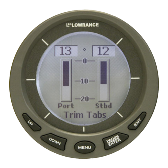
Page 19: Trim Tabs
NOTE: The LMF-400 can have up to 16 pages in the page screen rotation at one time. If you try to add a 17th page, the following message will appear: Number of Pages has Reached Max. In that case, you will have to remove a page before another page can be added to the page screen rotation. -
Page 20: Remove Page
Remove Page The Removing Pages command allows you to remove pages from the page screen rotation. Before selecting Remove Pages, make sure the page you want to remove is displayed on the screen. To remove a page from the display: 1. - Page 21 3. The Pop-Ups Setup menu will appear with five options: RPM, Engine Trim, Trim Tabs, Rudder and Stay-on Time. Select and press . The RPM menu will appear with two options: Off and Set ENTER Threshold. 4. Highlight and press .
-
Page 22: Screen
Accessing the Screen menu allows you to make adjustments to the appearance of the screen. There are three options: Backlight, Contrast and Reverse Video. Backlight The Backlight feature allows you to brighten or dim the light in the LMF-400. To adjust Backlight: 1. Press , use the keys to select... -
Page 23: Backlight Sync (Blight Sync)
Sync menu with two options: On and Off. Turning on Backlight Sync will cause the backlight level for all gauges on the LowranceNet to be synchronized with the backlight level on your LMF-400. 4. Select the desired option ( ) and press... -
Page 24: Reverse Video
Reverse Video The Reverse Video function swaps the position of dark and light colors on the screen. The dark text, which is on top of a light background, will be switched to light text on top of a dark background. This feature, typically, is used to darken the display for nighttime use. -
Page 25: Alarm Sound
3. Highlight to turn Key Sounds on or to turn Key Sounds off. Press . You will be taken back to the main display. ENTER Alarm Sound When an alarm is set and Alarm Sound is turned on, you will hear a tone and see a pop-up window when an alarm is triggered. -
Page 26: Bus Devices
depending on the number of engines chose during Boat Setup. The options are All Engines, Port, Center, Starboard and Off. The default setting is All Engines. (If you have a single-engine configuration, the only options on the Engine Warning menu will be on and off.) 1. -
Page 27: Engine/Tank Configuration
4. Select and press to open the Set Depth menu. ENTER EPTH (Choose to turn off the Shallow Alarm). 5. Use the keys to set the alarm to the desired depth and DOWN press . Press to return to the Sonar Alarms menu. ENTER EXIT To set the Deep Alarm:... -
Page 28: Reset Values
You will be taken back to the main ENTER display. WARNING: Resetting values is a hard reset. All LMF-400 settings will be set back to factory defaults. Resetting values, however, does not affect engine/tank configuration or the calibration and configuration settings of devices on... -
Page 29: Nmea Info
ENTER EXIT back to the main display. System Information Access the system information screen to see what version of software you have in your LMF-400. To access the System Information screen: 1. Press , use the keys to select MENU... -
Page 30: Change Units
Quad Analog. Pressure Range can make on-screen gauges easier to read by allowing you to select a range that will better fit your vessel’s pressure range. If, for example, your vessel's water pressure range is 0- 30 PSI, the unnecessary figures (31-100 PSI) will only crowd the gauge display, making it harder to read. - Page 31 1. Press , use the keys to select MENU DOWN YSTEM ETUP press ENTER 2. Highlight and press . Select and press ENTER HANGE NITS PEED to open the Speed and Distance menu. ENTER 3. Select the desired option — —...
-
Page 32: Fuel Setup
Source, Reset Trip Fuel and Reset Seasonal Fuel. Refill Tank The Refill Tank command ensures the LMF-400 fuel reading is consistent with the actual amount of fuel in your tank(s). The Refill Tank command must be used with the EP-10 Fuel Flow, EP-50 Storage Device and the Suzuki NMEA 2000 Engine Interface. -
Page 33: Partial Fill
Economy Speed Source The Economy Speed menu allows you to choose what speed source the LMF-400 will use to calculate Fuel Economy. A NMEA 2000 GPS module, like the LGC-2000, measures ground speed The EP-25 Paddlewheel and NMEA 2000 Pitot tube measure water speed. -
Page 34: Fuel Remaining Source
NOTE: Ground Speed is the default speed source for Fuel Economy. To change Economy Speed source: 1. Press , use the keys to select MENU DOWN YSTEM ETUP press . Select and press ENTER ENTER ETUP 2. Highlight and press to open the Economy Speed ENTER CO SPEED... -
Page 35: Reset Seasonal
3. Select the desired option and press . The following message ENTER will appear: Press Enter to reset Trip Fuel. 4. Press , which will reset the trip fuel and take you back to the ENTER main display. Reset Seasonal A few sensors, like the Suzuki Engine Interface, EP-10 Fuel Flow and EP-50 Storage Device keep a running total of fuel used for a season. -
Page 36: Single Analog
Basic menu with Customize highlighted. Single Analog The Single Analog page may be customized to display these data types: Alt Voltage, Battery Voltage, Engine Temp, Engine Water Pressure, Engine Pressure, Fuel Pressure, Engine Boost Pressure, Transmission Oil Pressure, Atmospheric Pressure, Temperature, Fluid Level, Water Speed (Paddlewheel), Ground Speed (GPS), and Tachometer. -
Page 37: Dual Analog
Dual Analog The Dual Analog page consists of two analog gauges and may be customized to show these data types: Alt Voltage, Battery Voltage, Engine Temp, Engine Water Pressure, Engine Oil Pressure, Fuel Pressure, Engine Boost Pressure, Transmission Pressure, Atmospheric Pressure, Temperature, Fluid Level, Water Speed (Paddlewheel), Ground Speed (GPS), and Tachometer. -
Page 38: Single Digital
6. Press to get back to the Quad Analog page, where the data EXIT EXIT you selected will be displayed. NOTE: If a page is customized to show information from a device that is working improperly or is not connected to the NMEA 2000 network, the data boxes on the gauge will flash. - Page 39 Battery Voltage, Engine Temperature, Engine Water Pressure, Engine Oil Pressure, Fuel Pressure, Engine Boost Pressure, Transmission Oil Pressure, Atmospheric Pressure, Temperature, Depth, Engine Load, Total Engine Hours, Fuel Flow, Fuel Economy, Fuel Remaining, Fuel Used, Fuel Range, Trip Fuel Use, Seasonal Fuel, Water Speed (Paddle Wheel Speed), Ground Speed (GPS) and Tachometer.
-
Page 40: Quad Digital
Dual Digital page (left) with Quad Digital page (right). Quad Digital The Quad Digital page has four digital data boxes, stacked one on top of the other. The digital data boxes can display: Alternator Voltage, Battery Voltage, Engine Temperature, Engine Water Pressure, Engine Oil Pressure, Fuel Pressure, Engine Boost Pressure, Transmission Oil Pressure, Atmospheric Pressure, Temperature, Depth, Engine Load, Total Engine Hours, Fuel Flow, Fuel Economy, Fuel Remaining, Fuel... -
Page 41: Trim Tabs
three options: Port, Center and Starboard. The data you selected will originate from the engine you choose. Select the desired engine and press . You will be taken back to the Data Box menu. ENTER Highlight the other digital data boxes and repeat steps 4-5. 6. - Page 42 3. Press , select and press . The data location MENU ENTER USTOMIZE menu will appear with three options: Top Data, Center Data and Bottom Data. 4. Highlight the desired data location and press . A list of data ENTER types will appear.
-
Page 43: Section 4: Ep Configuration & Calibration
Section 4: EP Configuration & Calibration To configure items connected to the LowranceNET, press , select MENU and press . Highlight and press ENTER ENTER YSTEM ETUP EVICES open the Bus Devices list. Bus Devices works as the device manager for the bus, allowing you to configure and unconfigure devices and set and reset critical values such as alarms and calibration. - Page 44 To unconfigure an EP-35 temp sensor: 1. Press , use the keys to select MENU DOWN YSTEM ETUP press ENTER 2. Highlight and press . The Bus Devices list will ENTER EVICES appear, showing all devices detected on the network. 3.
-
Page 45: Ep-10 Fuel Flow Configuration
EP-10 Fuel Flow Configuration You can have up to three fuel flow sensors installed on your vessel, one for each engine supported by the LMF-400. The number of fuel flows listed on the Bus Devices list depends on the engine-tank configuration you chose during Boat Setup. - Page 46 To reconfigure an EP-10 Fuel Flow: You will use the Change Engine command to reconfigure a Fuel Flow. Change Engine, however, will only appear on your LMF-400 menu if you have more than one engine. If all the fuel flows on your vessel are configured, you will have to unconfigure a fuel flow to free up its configuration name (Port, Center, Starboard).
- Page 47 Change Engine (active only with multiple-engine setting) The steps below show how to switch the configuration name of a fuel flow from the port engine to the starboard engine. If all fuel flows configured (Configuration name unavailable): 1. Press , use the keys to select MENU DOWN...
-
Page 48: Ep-15 Fluid Level Configuration
EP-15 Fluid Level Configuration The LMF-400 will support up to three tanks for each Fluid Level type which includes: Fuel, Fresh Water, Oil, Black Water, Waste Water (Gray Water) and Live Well. -
Page 49: Fluid Level Menu
Like a fuel tank, the Oil Tank will also be listed by its engine location — Oil Tank (P), Oil Tank (C) or Oil Tank (S). When setting fluid level configuration for the other fluid types you will be given the opportunity to assign the tank a number in case you have more than one tank of that fluid type. - Page 50 To configure EP-15 for Fresh Water: 1. Press , use the keys to select MENU DOWN YSTEM ETUP press ENTER 2. Highlight and press . The Bus Devices list will ENTER EVICES appear. 3. Select and press . The following message will ENTER NFCG appear: Press Enter to configure Fluid Lev Snsr.
- Page 51 3. Select and press . The following message will ENTER NFCG appear: Press Enter to configure Fluid Lev Snsr. Press and the ENTER Fluid Level configuration menu will appear. 4. Choose and press . The Tank Number window will ENTER appear.
-
Page 52: Level Warning
5. Use the keys to input the number you want to assign DOWN to the tank and press . The Setting Tank Size window will ENTER appear on the screen. 6. Use the keys to input the size of the tank and press DOWN . -
Page 53: Reset Values
To set a Level Warning: 1. Press , use the keys to and press MENU DOWN YSTEM ETUP MENU 2. Highlight and press . The Bus Devices list will ENTER EVICES appear. 3. Select the desired fluid level and press ENTER 4. -
Page 54: Suzuki Engine Interface Configuration
Suzuki Engine Interface Configuration You can have up to three Suzuki Engine Interface's installed on your vessel, one for each engine the LMF-400 supports. In a three engine- tank configuration, the interfaces will be listed as Port Engine, Center Engine and Stbd Engine. If the engine interface is unconfigured, it will be listed as Uncfg Eng Int. - Page 55 Suzuki Engine Interface with the configuration from a different engine. Change Engine, however, will only appear on your LMF-400 menu if you are using an engine-tank configuration that includes multiple engines. If all engine interfaces on your vessel are configured, you will have to unconfigure an interface to free up its configuration name (Port, Center, Starboard).
- Page 56 2. Highlight and press . The Bus Devices list will ENTER EVICES appear. 3. Select and press . Highlight and press ENTER NGINE NSET NGINE . The following message will appear: Press Enter to UnConfig ENTER Device Name. 4. Press .
-
Page 57: Calibrating Ep Sensors
2. Highlight and press to open the Bus Devices list. ENTER EVICES 3. Select the desired engine interface and press . That will open ENTER the Engine Interface menu. 4. Highlight and press . The Select Level menu will ENTER appear with two options: Low Level and High Level. -
Page 58: Calibrating Ep-10 Fuel Flow
standard fluid level gauges. If, however, the tank has an irregular shape or greater accuracy is needed, calibration is recommended. The default calibration for the EP-10 Fuel Flow and Suzuki Engine Interface are adequate in most cases, but if Fuel Used readings are off by more than 3 percent, calibration is recommended. - Page 59 Check the Fuel Manager page for the fuel used figure calculated by the LMF-400. 7. Compare the amount of fuel added when you filled up the tank with the LMF-400 Fuel Used figure.
-
Page 60: Reset Calibration
NOTE: It is a good idea to periodically check the calibration of a fuel flow. Reset Calibration The Reset Calibration command allows you to set fuel flow calibration back to default settings. To Reset Calibration for EP-10 Fuel Flow: 1. Press , use the keys to select MENU... -
Page 61: 2-Point Calibration
2-Point Calibration A 2-point calibration is best suited for rectangular or square-shaped tanks, where the capacity of the top half of the tank matches the capacity in the lower half of the tank. In a two-point calibration, you will set two points, one each for empty and full levels. You can begin calibration at either of the two points, but we recommend starting with an empty tank. -
Page 62: 5-Point Calibration
Level and Full Level) in any order you wish. Remember: Points that are not calibrated will not be as accurate as points that have been calibrated. For the greatest accuracy, we recommend all three points be calibrated. To execute 3-Point calibration: 1. -
Page 63: Reset Calibration
To execute 5-Point calibration: 1. Before following the steps below, make sure your fuel tank is empty. Press , use the up and down keys to select and press MENU YSTEM ETUP ENTER 2. Highlight and press . Choose the fluid level you ENTER EVICES want to calibrate and press... -
Page 64: Calibrating Fuel Flow In A Suzuki Engine Interface
3. Highlight from the fluid level menu and press . The ENTER ESET following message will appear: Press Enter to reset Calibration. 4. Press to set calibration back to factory default settings. You, ENTER then, will be returned to the bus devices list. NOTE: If you have calibrated your fluid level sensor and are having problems with the sensor's performance, be sure to check the... -
Page 65: Refill Tank
Suzuki Engine Interface. 6. Compare the amount of fuel added when you filled up the tank with the Fuel Used figure shown on the LMF-400. If the difference between these two numbers is greater than 3 percent, you need to calibrate the interface. -
Page 66: Reset Fuel Calibration
12. Repeat these steps for each engine interface you want to calibrate. NOTE: The LMF-400 will not let you input an amount of fuel greater than the fuel used figure. Reset Fuel Calibration The Reset Calibration command allows you to reset engine interface calibration back to default settings. -
Page 67: Calibrating Ep-30 Trim Tabs
4. Highlight the tank you partially filled and press . That will ENTER open the Adding Fuel window. 5. Use the keys to enter the amount of fuel you added to DOWN the tank and press . You will be taken back to the main display. ENTER Calibrating EP-30 Trim Tabs Trim Tabs are calibrated though the Trim Tab pages menu. - Page 68 Notes...
- Page 69 LOWRANCE ELECTRONICS FULL ONE-YEAR WARRANTY "We," "our," or "us" refers to LOWRANCE ELECTRONICS, INC., the manufacturer of this product. "You" or "your" refers to the first person who purchases this product as a consumer item for personal, family or household use.
- Page 70 …in the USA: We back your investment in quality products with quick, expert service and genuine Lowrance parts. If you're in the United States and you have technical, return or repair questions, please contact the Factory Customer Service Department. Before any product can be returned, you must call customer service to determine if a return is necessary.
- Page 71 To locate a Lowrance dealer near you, visit our web site, www.lowrance.com and look for the Dealer Locator. Or, you can consult your telephone directory for listings.
- Page 72 Visit our web site: Lowrance Pub. 988-0151-222 © Copyright 2006 All Rights Reserved Printed in USA 121306 Lowrance Electronics, Inc.
Need help?
Do you have a question about the LMF-400 and is the answer not in the manual?
Questions and answers