Advertisement
Quick Links
EP-15 Fluid Level
This instruction sheet tells how to install your EP-15 Fluid Level
sensor and connect it to a NMEA 2000
network components. You must refer to your digital gauge, sonar or
GPS unit's manual for sensor operation instructions.
Caution:
Installing LowranceNET NMEA 2000 devices is significantly
different from installing earlier Lowrance components without
NMEA 2000 features. You should read all of the installation
instructions before proceeding. You should decide where to
install all components before drilling any holes in your vessel.
Some sonar or GPS units may require a software upgrade to display
NMEA 2000 data correctly and a manual addendum describing how to
operate the sensor. You can download these free and get additional
information on the NMEA 2000
our web site, www.lowrance.com.
All Lowrance NMEA 2000 capable devices are either NMEA 2000
certified or certification is pending. See our web site for the latest
product status information.
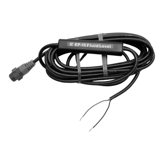
Smart
module
Blue female NMEA
2000 connector
Electronic Sensor
Installation Instructions
The EP-15 Fluid Level sensor.
network using LowranceNET
compatible LowranceNET system at
1
Pub. 988-0154-371
Sending unit
connections:
red lead and
black lead.
Advertisement

Related Manuals for Lowrance EP-15


Summary of Contents for Lowrance EP-15
-
Page 1: Installation Instructions
EP-15 Fluid Level Electronic Sensor Installation Instructions This instruction sheet tells how to install your EP-15 Fluid Level sensor and connect it to a NMEA 2000 network components. You must refer to your digital gauge, sonar or GPS unit's manual for sensor operation instructions. - Page 2 The EP-15 consists of a smart module with a blue female locking cable connector on one end and two bare wires on the other. The cable length from the connector to the smart module is 18 inches (46 cm) and from the smart module to the bare wires is 10 feet (3 meters).
- Page 3 Sending unit mounting plate configurations vary. When connecting the EP-15, you will need whatever tools and supplies that will work with your sending unit's specific design. Recommended tools include: pliers. If you need to route the smart module or cable connector through a bulkhead, you will need a drill and a 7/8"...
- Page 4 The center threaded post is + and the blade is – . Finally, connect the blue locking collar connector to the NMEA 2000 network. Route the sensor's cable connector to the T on the network backbone where you intend to attach it, and plug it in.
- Page 5 T connector. Existing network node Add a new device to a NMEA 2000 bus by attaching a T connector between two T connectors, between a T connector and the end terminator, or between two backbone extension cables.
- Page 6 The "soft" T connector, shown above with a "hard" T connector, is another option for connecting devices in a NMEA 2000 network. The soft T works the same as a hard T. The soft T is used to install a network node in areas...
- Page 7 LOWRANCE ELECTRONICS FULL ONE-YEAR WARRANTY "We," "our," or "us" refers to LOWRANCE ELECTRONICS, INC., the manufacturer of this product. "You" or "your" refers to the first person who purchases this product as a consumer item for personal, family or household use.
-
Page 8: Accessory Ordering Information
For Eagle: 8 a.m. to 5 p.m. Central Standard Time, M-F Lowrance Electronics and Eagle Electronics may find it necessary to change or end their shipping policies, regulations and special offers at any time. They reserve the right to do so without notice.
Need help?
Do you have a question about the EP-15 and is the answer not in the manual?
Questions and answers