Table of Contents
Advertisement
Available languages
Available languages
Quick Links
MANUALE D'USO / USER MANUAL
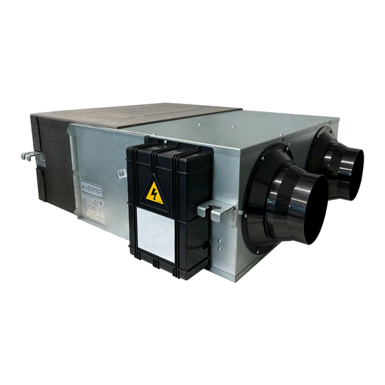
HI-TECH PUR 4.0
ENTALPICO CANALIZZABILE DA SOFFITTO
• ACD300002 - Recuperatore di calore entalpico HI-TECH PUR 4.0 250m
• ACD300003 - Recuperatore di calore entalpico HI-TECH PUR 4.0 500m
• ACD300004 - Recuperatore di calore entalpico HI-TECH PUR 4.0 800m
• ACD300005 - Recuperatore di calore entalpico HI-TECH PUR 4.0 1000m
• ACD300006 - Recuperatore di calore entalpico HI-TECH PUR 4.0 1300m
Tecnosystemi S.p.A. - Società Benefit
www.tecnosystemi.com
via dell'Industria, 2/4 - Z.I. San Giacomo di Veglia
31029 Vittorio Veneto (Treviso) - Italy
Phone +39 0438.500044 Fax +39 0438.501516
RECUPERATORE
4.0
Numero Verde 800 904474
email: info@tecnosystemi.com
C.F. - P. IVA - R.I.TV IT02535780247 | Cap. Soc. € 5.000.000,00 i.v.
COD. CMU00127
REV. 02 / 16-01-2024
/h
3
/h
3
/h
3
3
3
(only for Italy)
/h
/h
Advertisement
Chapters
Table of Contents

Related Manuals for Tecnosystemi HI-TECH PUR 4.0


Summary of Contents for Tecnosystemi HI-TECH PUR 4.0
- Page 1 HI-TECH PUR 4.0 RECUPERATORE ENTALPICO CANALIZZABILE DA SOFFITTO • ACD300002 - Recuperatore di calore entalpico HI-TECH PUR 4.0 250m • ACD300003 - Recuperatore di calore entalpico HI-TECH PUR 4.0 500m • ACD300004 - Recuperatore di calore entalpico HI-TECH PUR 4.0 800m •...
-
Page 2: Table Of Contents
INDICE 1_AVVERTENZE GENERALI 2_DESCRIZIONE 2.1 INTRODUZIONE 2.2 INDICAZIONI GENERALI 2.3 SCOPO E CONTENUTO DELLE ISTRUZIONI 2.4 CONSERVAZIONE DELLE ISTRUZIONI 2.5 AGGIORNAMENTO DELLE ISTRUZIONI 2.6 COME UTILIZZARE QUESTE ISTRUZIONI 2.7 RISCHI RESIDUI 2.8 GENERALITÀ SULLA SIMBOLOGIA DI SICUREZZA 2.9 SIMBOLI DI SICUREZZA UTILIZZATI 2.10 LIMITI DI UTILIZZO E USI NON CONSENTITI 2.11 IDENTIFICAZIONE DELL’UNITÀ... -
Page 3: 1_Avvertenze Generali
Qualsiasi operazione d’installazione e/o manutenzione del prodotto deve essere eseguita esclusivamente da personale professionalmente qualificato ed abilitato. TECNOSYSTEMI S.p.A. Società Benefit declina ogni responsabilità per eventuali danni causati da una non corretta installazione ed uso improprio o manomissione del controllo. -
Page 4: 2_Descrizione
Le presenti istruzioni d’uso e installazione del prodotto, sono scaricabili e disponibili sul sito web www.tecnosystemi.com oppure possono essere richieste all’indirizzo mail assistenza@tecnosystemi. com, indicando modello e serial number del dispositivo. -
Page 5: Come Utilizzare Queste Istruzioni
2.6 COME UTILIZZARE QUESTE ISTRUZIONI Le istruzioni sono parte integrante della macchina. Prima di ogni operazione sulla macchina, gli utilizzatori o gli operatori sono tenuti a consultare le istruzioni e a farlo anche in caso di incertezza riguardante il trasporto, la movimentazione, l’installazione, la manutenzione, l’utilizzo e lo smantellamento della macchina. - Page 6 • Fare attenzione nel sollevamento dell’unità il cui baricentro può anche essere fortemente sbilanciato; • Fare attenzione nel bloccaggio delle funi/ganci di sollevamento; • Fare attenzione agli spigoli di lamiera all’interno dell’unità; • Fare attenzione agli spigoli di lamiera all’esterno dell’unità; •...
-
Page 7: Generalità Sulla Simbologia Di Sicurezza
2.8 GENERALITÀ SULLA SIMBOLOGIA DI SICUREZZA Simboli di sicurezza singoli in conformità alla norma ISO 3864-2: DIVIETO Un simbolo nero inserito in un cerchio rosso con diagonale rossa indica un’azione che non deve essere eseguita. AVVERTENZA Un simbolo grafico nero inserito in un triangolo giallo con bordi neri indica un pericolo. AZIONE OBBLIGATORIA Un simbolo bianco inserito in un cerchio blu indica un’azione che deve essere fatta per evitare un rischio. -
Page 8: Limiti Di Utilizzo E Usi Non Consentiti
Verificare che le caratteristiche della rete elettrica siano conformi ai dati riportati sulla targhetta di identificazione. Un FAC-SIMILE della targhetta è visualizzata qui sotto con la relativa legenda dei dati in essa riportati: Via dell'Industria, 2/4, 31029 Vittorio Veneto TV. ITALY T:0438 500044 info@tecnosystemi.com HEAT RECOVERY VENTILATION UNIT Part Number: ACD300002 Model:... -
Page 9: 3_Caratteristiche Tecniche
3_CARATTERISTICHE TECNICHE 3.1 DATI DI TARGA DATI ELETTRICI E PRESTAZIONALI ACD300002 ACD300003 ACD300004 ACD300005 ACD300006 Portata (m3/h) 1000 1300 Portata (l/s) Pressione esterna (Pa) COOLING 62-71 60-74 63-71 60-70 56-68 EFF. ENTALPICA (%) HEATING 65-73 63-78 65-75 62-72 59-70 EFF. TEMP. (%) RUMORE DB(A) 34.5 ALIMENTAZIONE ELETTRICA... -
Page 10: Caratteristiche Tecniche Recuperatore
3.2 DATI DI PROGETTAZIONE ECOCOMPATIBILE In accordo a Regolamento (UE) N. 1253/2014 della Commissione Europea recante attuazione della direttiva 2009/125/CE. a) Brand Tecnosystemi b) Modello ACD300002 ACD300003 ACD300004 ACD300005 ACD300006 c) Tipologia UVNR, UVB - Unità di ventilazione non residenziale, bidirezionale d) Tipo di azionamento A 10 velocità... -
Page 11: Grafici Portate E Rendimenti
3.3 GRAFICI PORTATE E RENDIMENTI I grafici sotto riportati indicano i limiti operativi dei ventilatori EC installati sulle unità. La prevalenza statica riportata si deve intendere utile per le canalizzazioni. Curve prestazionali ACD300002 Flusso (m Curve prestazionali ACD300004 Curve prestazionali ACD300003 Flusso (m Flusso (m... - Page 12 Curve prestazionali ACD300005 Flusso (m Curve prestazionali ACD300006 Flusso (m...
-
Page 13: 4_Installazione
4_INSTALLAZIONE AVVERTENZE GENERALI ED USO DEI SIMBOLI Tutte le operazioni effettuate sulla macchina devono essere eseguite da personale abilitato in ottemperanza alla legislazione nazionale vigente nel paese di destinazione. L’installazione e la manutenzione della macchina devono essere eseguite secondo le norme nazionali o locali in vigore. -
Page 14: Ricevimento Ed Ispezione
4.1 RICEVIMENTO ED ISPEZIONE All’atto dell’installazione o quando si debba intervenire sull’unità, è necessario attenersi scrupolosamente alle norme riportate su questo manuale, osservare le indicazioni a bordo unità e comunque applicare tutte le precauzioni del caso. La mancata osservanza delle norme riportate può causare situazioni pericolose. All’atto del ricevimento dell’unità, verificarne l’integrità: la macchina ha lasciato la fabbrica in perfetto stato;... - Page 15 MODELLO A [mm] B [mm] C [mm] D [mm] E [mm] F [mm] G [mm] L [mm] K [mm] M [mm] M1 [mm] M2 [mm] N [mm] ACD300003 833.5 20.5 451.5 115.5 139.5 Φ194 ACD300004 1134 1134 1068 1189 20.5 Φ242 MODELLO A [mm] B [mm] C [mm] D [mm] E [mm] F [mm] G [mm] L [mm] K [mm] M [mm] M [mm] M2 [mm] N [mm]...
-
Page 16: Installazione A Soffitto
4.5 INSTALLAZIONE A SOFFITTO L’installazione e la manutenzione vanno eseguiti solo da personale qualificato. Durante tutte le procedure di installazione, assicurarsi che l’apparecchiatura non sia collegata alla rete elettrica. L’installazione deve essere effettuata solo all’interno degli edifici. Nel caso di soffitti inclinati o irregolari assicurarsi di posizionare la macchina a soffitto con un’inclinazione del 2 % (2 cm circa ogni 1 m) verso lo scarico condensa. - Page 17 La macchina è progettata per essere installata a controsoffitto, con la possibilità di canalizzare l’aria da trattare o trattata. Di solito, viene posizionata in vani tecnici o disimpegni, con le canalizzazioni in mandata preferite per la distribuzione dell’aria trattata nei vari locali. Il fissaggio dell’apparecchiatura avviene mediante una staffa di ancoraggio, fornita insieme al recuperatore, che viene utilizzata per ancorare la macchina al solaio o al pavimento.
- Page 18 Curva di saturazione Temperatura di bulbo secco (°C) 9. Per evitare che l’aria di scarico esterna ritorni all’interno, la distanza tra le due prese d’aria installate sulla parete esterna deve essere superiore a 1000 mm. 10.Se l’unità è dotata di riscaldatore, il funzionamento del riscaldatore deve essere sincronizzato con l’unità, in modo che il riscaldatore inizia a funzionare solo all’avvio dell’unità.
-
Page 19: Aeraulica
4.6 AERAULICA Si consiglia l’installazione di almeno 500 mm di tubazione flessibile per evitare trascinamenti di vibrazione e fastidiosi rumori dovuti all’installazione. PER MODELLO ACD300002 Tubo dell’aria fresca Tubo dell’aria fresca esterno Asta per sospensione Aria di alimentazione Aria di ritorno Tubo di scarico Uscita aria di scarico Ingresso... - Page 20 È importante che l’aria di rinnovo venga aspirata dall’esterno dell’edificio e che l’aria esausta venga espulsa all’esterno. Inoltre, è consigliabile installare delle griglie di protezione per le tubazioni sul lato esterno. Quando si effettua la prima connessione dell’impianto di aerazione, è necessario fare riferimento al quadro elettrico presente sulla macchina. Le tubazioni di collegamento verso l’esterno devono essere isolate per prevenire la formazione di condensa.
-
Page 21: Elettrica
4.7 ELETTRICA (Collegamenti elettrici) Informazioni preliminari di sicurezza La connessione elettrica deve essere realizzata secondo lo schema elettrico allegato all’unità ed in aderenza alle normative locali ed internazionali. Assicurarsi che la linea di alimentazione elettrica dell’unità sia sezionata a monte della stessa. Assicurarsi che il dispositivo di sezionamento sia lucchettato o che sulla maniglia di azionamento sia applicato l’apposito cartello di avvertimento a non operare. -
Page 22: Verifiche Preliminari
4.8 VERIFICHE PRELIMINARI Prima di procedere all’avviamento della macchina è necessario effettuare controlli preliminari della parte elettrica ed idraulica. Le operazioni di messa in servizio devono essere eseguite in conformità a tutte le prescrizioni dei paragrafi precedenti. Malfunzionamenti o danni possono derivare anche da mancanza di adeguate cure durante la spedizione e l’installazione. -
Page 23: Schema Elettrico
4.10 SCHEMA ELETTRICO Pre-Riscaldamento elettrico Riscaldamento elettrico Segnale funzionamento Segnale guasto... -
Page 24: Collegamento Porte Seriali - Bms E Console
Collegamenti alla rete elettrica: Il prodotto deve essere collegato alla rete elettrica per fornire l’alimentazione necessaria per il suo corretto funzionamento. Collegamenti Modbus: La console deve essere collegata alla recuperatore attraverso un cavo a 2 fili in doppio isolamento per lo scambio di informazioni alla rete RS-485. -
Page 25: Ingressi E Uscite Ausiliarie
Register range di lettura scrittura descrizione funzione note address valori 12(0x000c) √ Bypass switch, 1=on 0=off 13(0x000d) √ P-heating state 1=on 0=off √ R-Heating state 1=on 0=off √ √ √ √ √ √ √ √ √ 0-23 System time: hour √... -
Page 26: 5_Interfaccia Utente
5_INTERFACCIA UTENTE 5.1 INSTALLAZIONE E FUNZIONALITÀ CONTROLLO DA PARETE Terminale ambiente che, unito al controllo programmabile, permette all’utente la regolazione del comfort ambiente residenziale, dotato di sonda di temperatura. 5.2 AVVERTENZE PER L’INSTALLAZIONE • Questi terminali sono stati progettati per il montaggio a incasso, con scatola conforme alle normative vigenti; •... - Page 27 Blocco schermo Per evitare tocchi accidentali, il display può essere bloccato: premere il pulsante ON/OFF per più di 6 secondi per bloccare lo schermo e premerlo nuovamente per più di 6 secondi per sbloccarlo. Il simbolo del lucchetto acceso sopra l’orologio indica che lo schermo è...
- Page 28 • Modalità impostazione CO2 (visibile solo se la funzione è abilitata, vedi capitolo 6.4 ELENCO PARAMETRI) Umidità corrente Umidità impostata • Modalità impostazione umidità (visibile solo se la funzione è abilitata, vedi capitolo 6.4 ELENCO PARAMETRI) • Modalità timer (vedi paragrafo “impostazione del timer” sotto) •...
-
Page 29: Funzionamento E Impostazione Del By-Pass
Impostazione del timer Tramite il tasto MODE entrare nella modalità timer (vedi paragrafo sopra “Visualizzazione dei dati e modalità funzionamento”). Premere brevemente il pulsante SET. I giorni della settimana lampeggeranno. Premendo i tasti SU e GIÙ si può selezionare il giorno della settimana. -
Page 30: Elenco Parametri
Esterno Soglia Estate Soglia Inverno Tempo Bypass 100% Tempo 6.4 ELENCO PARAMETRI Premere il pulsante MODE per più di 6 secondi per entrare nell’interfaccia impostazione parametri: numero del parametro valore del parametro Scorrere l’elenco parametri passando da un parametro all’altro premendo brevemente il pulsante “SET”. All’indice del parametro desiderato, premere i pulsati freccia SU/GIÙ... - Page 31 Descrizione Valori possibili Default Unità di misura Riavvio da buco di tensione 0 - disabilitato, 1 - abilitato Funzione bypass automatico 0 - disabilitato, 1 - abilitato Temperatura di apertura del bypass (X) 5-30 °C Range di temperatura di apertura del 2-15 °C bypass (Y)
-
Page 32: Allarme Filtro
A. Parametri 6, 7, 8, 9 – Sbrinamento convenzionale (defrosting). Quando la temperatura dell’aria in espulsione (FR/EA) si mantiente inferiore alla temperatura di sbrinamento impostata (parametro 8) per almeno 1 minuto, e dal precedente ciclo di defrosting è passato almeno un tempo minimo (parametro 7), allora il ventilatore di immissione si arresta mentre il ventilatore di espulsione lavora alla massima velocità... -
Page 33: 7_Manutenzione Ordinaria
Codice Errore OA Errore sensore di temperatura Errore di memoria RA Errore sensore di temperatura EA Errore sensore di temperatura Errore di comunicazione SA Errore sensore di temperatura Errore allarme di incendio 7_MANUTENZIONE ORDINARIA ATTENZIONE: L’alimentazione deve essere isolata prima dell’installazione e della manutenzione per evitare lesioni o scosse elettriche. Fornitura i cavi di alimentazione, l’interruttore principale e la protezione differenziale devono essere conformi alle normative nazionali. -
Page 34: 8_Manutenzione Straordinaria
8_MANUTENZIONE STRAORDINARIA Le operazioni di messa in servizio devono essere eseguite in conformità a tutte le prescrizioni dei paragrafi precedenti. Tutte le operazioni effettuate sulla macchina devono essere eseguite da personale abilitato in ottemperanza alla legislazione nazionale vigente nel paese di destinazione. È... -
Page 35: 11_Diagnosi E Risoluzione Dei Problemi
11_DIAGNOSI E RISOLUZIONE DEI PROBLEMI Tutte le operazioni di messa fuori servizio devono essere eseguite da personale abilitato in ottemperanza alla legislazione nazionale vigente nel paese di destinazione. La struttura ed i vari componenti, se inutilizzabili, vanno demoliti e suddivisi a seconda della loro natura. Tutti i materiali devono essere recuperati o smaltiti in conformità... -
Page 36: 12_Garanzia
12_GARANZIA 1. La presente garanzia opera esclusivamente nei confronti del Cliente (persona giuridica) e non nei confronti del consumatore finale (persona fisica) al quale il Cliente abbia fornito il Prodotto. 2. La garanzia ha durata di anni 2 (due) a decorrere dalla data di consegna indicata sul d.d.t (bolla). 3. - Page 37 HI-TECH PUR 4.0 CEILING-MOUNTED DUCTED ENTHALPIC HEAT RECOVERY UNIT • ACD300002 - Enthalpic heat recovery unit HI-TECH PUR 4.0 250m • ACD300003 - Enthalpic heat recovery unit HI-TECH PUR 4.0 500m • ACD300004 - Enthalpic heat recovery unit HI-TECH PUR 4.0 800m •...
- Page 38 TABLE OF CONTENTS 1_GENERAL WARNINGS 2_DESCRIPTION 2.1 INTRODUCTION 2.2 GENERAL INDICATIONS 2.3 INSTRUCTIONS PURPOSE AND CONTENT 2.4 KEEPING THE INSTRUCTIONS 2.5 UPDATING THE INSTRUCTIONS 2.6 HOW TO USE THESE INSTRUCTIONS 2.7 RESIDUAL RISKS 2.8 GENERAL INFORMATION ON SAFETY SYMBOLS 2.9 SAFETY SYMBOLS USED 2.10 USE LIMITS AND PROHIBITED USES 2.11 UNIT IDENTIFICATION 3_TECHNICAL CHARACTERISTICS...
-
Page 39: 1_General Warnings
Any product installation and/or maintenance operation must be performed exclusively by professionally qualified and authorised personnel. TECNOSYSTEMI S.p.A. a Benefit Company declines all responsibility for any damage caused by incorrect installation and improper use or tampering with the control. During installation, maintenance and repairs, for safety reasons, the following are necessary: •... -
Page 40: 2_Description
This process ensures adequate ventilation of the internal environments, while reducing heat dispersion. This manual contains a detailed description of the technical specifications of the HI-TECH PUR 4.0 recovery units, the instructions for its operation, installation and assembly, as well as the technical data. -
Page 41: How To Use These Instructions
2.6 HOW TO USE THESE INSTRUCTIONS The instructions are an integral part of the machine. Before any operation on the machine, users or operators are required to consult the instructions and to do so also in the event of uncertainty regarding transportation, handling, installation, maintenance, use and dismantling of the machine. - Page 42 • Be careful when lifting the unit whose centre of gravity may also be very unbalanced; • Be careful when locking the lifting ropes/hooks; • Pay attention to the sheet metal edges inside the unit; • Pay attention to the sheet metal edges on the outside of the unit; •...
-
Page 43: General Information On Safety Symbols
2.8 GENERAL INFORMATION ON SAFETY SYMBOLS Individual safety symbols according to the ISO 3864-2 standard: PROHIBITION A black symbol inserted in a red circle with a red diagonal indicates an action that must not be performed. WARNING A black graphic symbol inserted in a yellow triangle with black borders indicates a danger. COMPULSORY ACTION A white symbol inserted in a blue circle indicates an action that must be performed to avoid a risk. -
Page 44: Use Limits And Prohibited Uses
Check that the characteristics of the electrical network comply with the data shown on the identification plate. A FAC- SIMILE of the plate is shown below with the relative legend of the data reported on it: Via dell'Industria, 2/4, 31029 Vittorio Veneto TV. ITALY T:0438 500044 info@tecnosystemi.com HEAT RECOVERY VENTILATION UNIT Part Number: ACD300002 Model:... -
Page 45: 3_Technical Characteristics
3_TECHNICAL CHARACTERISTICS 3.1 PLATE DATA ELECTRICAL AND PERFORMANCE DATA ACD300002 ACD300003 ACD300004 ACD300005 ACD300006 Airflow (m3/h) 1000 1300 Airflow (l/s) External pressure (Pa) COOLING 62-71 60-74 63-71 60-70 56-68 ENTH. EFF. (%) HEATING 65-73 63-78 65-75 62-72 59-70 TEMP. EFF (%) NOISE DB(A) 34.5 POWER SUPPLY... -
Page 46: Recovery Unit Technical Characteristics
3.2 RECOVERY UNIT TECHNICAL AND ECOCOMPATIBLE CHARACTERISTICS According to Commission Regulation (EU) No 1253/2014 implementing Directive 2009/125/EC. a) Brand Tecnosystemi b) Model ACD300002 ACD300003 ACD300004 ACD300005 ACD300006 c) Typology NRVU, BVU - Non-Residential Ventilation Unit, Bidirectional d) Type of drive... -
Page 47: Flow Rate And Airflow Graphs
3.3 FLOW RATE AND AIRFLOW GRAPHS The graphs below indicate the operating limits of the EC fans installed on the units. The reported static head must be considered useful for the ducts. Performance Chart ACD300002 Performance Chart ACD300004 Performance Chart ACD300003... - Page 48 Performance Chart ACD300005 Performance Chart ACD300006...
-
Page 49: 4_Installation
4_INSTALLATION GENERAL WARNINGS AND USE OF SYMBOLS All operations performed on the machine must be carried out by qualified personnel in compliance with the national legislation in force in the destination country. The installation and maintenance of the machine must be performed according to the national or local regulations in force. -
Page 50: Receipt And Inspection
4.1 RECEIPT AND INSPECTION When installing or servicing the unit, the rules indicated in this manual must be complied with, together with those on board the unit and, in any case, all necessary precautions must be taken. Failure to comply with these regulations may cause dangerous situations. - Page 51 MODEL A [mm] B [mm] C [mm] D [mm] E [mm] F [mm] G [mm] L [mm] K [mm] M [mm] M1 [mm] M2 [mm] N [mm] ACD300003 833.5 20.5 451.5 115.5 139.5 Φ194 ACD300004 1134 1134 1068 1189 20.5 Φ242 MODEL A [mm] B [mm] C [mm] D [mm] E [mm] F [mm] G [mm] L [mm] K [mm] M [mm] M1 [mm] M2 [mm] N [mm]...
-
Page 52: Ceiling Installation
4.5 CEILING INSTALLATION Installation and maintenance must only be performed by qualified personnel. During all installation procedures, make sure that the equipment is not connected to the mains. Installation must only be performed inside buildings. In the case of sloping or irregular ceilings be sure to position the machine on the ceiling with an inclination of 2% (approximately 2 cm every 1 m) towards the condensate drain. - Page 53 The machine is designed to be installed in a false ceiling, with the possibility of ducting of the air to be treated or that has been treated. It is usually positioned in technical rooms or corridors, with the preferred delivery ducts for the distribution of the treated air in the various rooms.
- Page 54 Saturation Curve Dry bulb temp. (°C) 9. To avoid the outdoor exhaust air cycling back to indoor, the distance between the two vents installed on the outside wall should be over 1000mm. 10.If heater is equipped to the unit, operation of heater should be synchronous with the unit, so that the heater starts to work only when unit starts.
-
Page 55: Aeraulics
4.6 AERAULICS We recommend the installation of at least 500 mm of flexible tubing to avoid the vibrations and annoying noises due to the installation. FOR MODEL: ACD300002 Fresh Air Duct / Outside Fresh Air Duct Suspending Pole Supply Air Return Air Exhaust Duct Exhaust Air Out... - Page 56 It is important that the fresh air is drawn in from outside the building and that the exhaust air is expelled outside. Furthermore, it is advisable to install protective grilles for the pipes on the outside. When making the first connection of the ventilation system, it is necessary to refer to the electrical panel on the machine.
-
Page 57: Electrics
4.8 ELECTRICS (Electrical connections) Preliminary safety information The electrical connection must be made according to the wiring diagram attached to the unit and in compliance with local and international regulations. Make sure that the power supply line of the unit is sectioned upstream of it. Make sure that the disconnecting device is padlocked or that a dedicated warning sign is applied to the operating handle. -
Page 58: Preliminary Checks
4.9 PRELIMINARY CHECKS Before starting up the machine, it is necessary to carry out preliminary checks on the electrical and hydraulic parts. Commissioning operations must be performed in compliance with all the provisions of the preceding paragraphs. Malfunctions or damage may also result from the lack of proper care during shipping and installation. It is good practice to check before installation or commissioning that there is no damage due to tampering, vibrations during transportation or mistreatment suffered on site. -
Page 59: Wiring Diagram
4.11 WIRING DIAGRAM Electrical preheating Electrical heating Running signal Fault signal... -
Page 60: Serial Ports Connection - Bms And Console
Connections to the main: The product must be connected to the mains to supply the power necessary for its correct operation. Modbus connections: The console must be connected to the recovery unit via a 2-wire double-insulated cable for the exchange of information on the RS-485 network. -
Page 61: Commissioning
Register range of readable writable function description remarks address value 12(0x000c) √ Bypass switch, 1=on 0=off 13(0x000d) √ P-heating state 1=on 0=off √ R-Heating state 1=on 0=off √ √ √ √ √ √ √ √ √ 0-23 System time: hour √... -
Page 62: 5_User Interface
5_USER INTERFACE 5.1 WALL CONTROL INSTALLATION AND FUNCTIONALITY Room terminal which, combined with the programmable control, allows the user to adjust the residential room comfort, equipped with a temperature probe. 5.2 INSTALLATION WARNINGS • These terminals have been designed for flush assembly, with a box compliant with the current regulations; •... - Page 63 Screen lock To avoid accidental touches, the display can be locked: press the ON/OFF button for more than 6 seconds to lock the screen and press it again for more than 6 seconds to unlock it. The lit padlock symbol above the watch indicates that the screen is locked Data display and operating mode By pressing the MODE button you can scroll through the following screens in sequence:...
- Page 64 • CO2 setting mode (visible only if the function is enabled, see chapter 6.4 SETTING PARAMETERS) • Humidity setting mode (visible only if the function is enabled, see chapter 6.4 SETTING PARAMETERS) • Timer mode (see “timer setting” paragraph below) •...
-
Page 65: By-Pass Operation And Setting
Timer setting Using MODE button enter the timer mode (see paragraph above “Data display and operating mode”). Short press SET button. The days of the week will flash. By pressing the UP and DOWN buttons you can select the day of the week. Short press SET to move in succession to setting the hours, minutes, supply fan speed (SA) and exhaust fan speed (EA). -
Page 66: Setting Parameters
Outside Temperature Esterno Summer Threshold Soglia Estate Winter Threshold Soglia Inverno Time Tempo Bypass 100% Time Tempo 6.4 SETTING PARAMETERS: Press MODE button for more than 6 seconds to enter the parameter setting interface: Parameter Number Parameter Value Scroll through the parameter list moving from one parameter to another by shortly pressing SET button. At the desired parameter number, press UP/DOWN arrow buttons to adjust the parameter value. -
Page 67: Filter Alarm
Contents Range Default Unit Restart after blackout 0 - disabled, 1 - enabled Automatic bypass function 0 - disabled, 1 - enabled Bypass opening temperature X 5-30 °C Bypass opening temperature range 2-15 °C Electric heating setting 0 - disabled, 1 - enabled Conventional defrosting 0 - disabled, 1 - enabled Defrost interval... -
Page 68: Restore Factory Setting
A. Parameters 6, 7, 8, 9 – Conventional defrosting. When the temperature of the exhaust air (FR/EA) remains lower than the set defrost temperature (parameter 8) for at least 1 minute, and at least a minimum amount of time has passed since the previous defrosting cycle (parameter 7), then the supply fan stops while the exhaust fan works at maximum speed until an exhaust air temperature of 15°C is reached for one minute or until the maximum time of the defrosting cycle (parameter 9). -
Page 69: 7_Ordinary Maintenance
Code Error OA temperature sensor error Memory error RA temperature sensor error EA temperature sensor error communication error SA temperature sensor error Fire alarm error 7_ORDINARY MAINTENANCE WARNING: Power must be isolated before installation and maintenance to avoid injury or electricsshock. Supply power cables, main circuit breaker and earth leakage protection, must comply with national regulations. -
Page 70: 8_Extraordinary Maintenance
8_EXTRAORDINARY MAINTENANCE Commissioning operations must be performed in compliance with all the provisions of the preceding paragraphs. All operations performed on the machine must be carried out by qualified personnel in compliance with the national legislation in force in the destination country. It is good practice to perform periodic checks to verify the correct functioning of the unit, of the control and safety devices. -
Page 71: 11_Troubleshooting
11_DIAGNOSIS AND TROUBLESHOOTING All the decommissioning operations must be performed by qualified personnel in compliance with the national legislation in force in the destination country. The structure and the various components, if unusable, must be demolished and divided according to their nature. All the materials must be recovered or disposed of in compliance with the relevant national regulations. -
Page 72: 12_Warranty
12_WARRANTY 1. This warranty applies exclusively to the Customer (legal person) and not to the end consumer (natural person) to whom the Customer has supplied the Product. 2. The warranty is valid for 2 (two) years starting from the delivery date indicated on the Transport Document (delivery note). - Page 73 NOTE NOTES...
- Page 74 NOTE NOTES...
- Page 75 NOTE NOTES...
- Page 76 Tecnosystemi S.p.A. Società Benefit www.tecnosystemi.com via dell’Industria, 2/4 - Z.I. San Giacomo di Veglia 31029 Vittorio Veneto (Treviso) - Italia Tel +39 0438.500044 - Fax +39 0438.501516 email: info@tecnosystemi.com 800 904474 ONLY FOR ITALY C.F. - P. IVA - R.I.TV IT02535780247 Cap.
Need help?
Do you have a question about the HI-TECH PUR 4.0 and is the answer not in the manual?
Questions and answers