Table of Contents
Advertisement
Available languages
Available languages
Quick Links
MANUALE D'USO
ASPIRATORE-ESTRATTORE DA PARETE CON ALIMENTATORE
ESTERNO O AD INCASSO - "PICO CLEAN WI"
Tecnosystemi S.p.A.
via dell'Industria, 2/4 - Z.I. San Giacomo di Veglia
31029 Vittorio Veneto (Treviso) - Italia
Tel +39 0438.500044 - Fax +39 0438.501516
Numero Verde 800 904474 (only for Italy)
email: info@tecnosystemi.com
C.F. - P. IVA - R.I.TV IT02535780247 Cap. Soc. € 5.000.000,00 i.v.
ACD100025 - ACD100026 - ACD100027
ACD100028 - ACD100029 - ACD100030
COD. CMU00032
REV. 01 / 19-09-2019
Sistemi
www.tecnosystemi.com
WI-FI
Advertisement
Table of Contents

Related Manuals for Tecnosystemi PICO CLEAN WI ACD100025


Summary of Contents for Tecnosystemi PICO CLEAN WI ACD100025
- Page 1 ACD100025 - ACD100026 - ACD100027 ACD100028 - ACD100029 - ACD100030 WI-FI Sistemi Tecnosystemi S.p.A. via dell’Industria, 2/4 - Z.I. San Giacomo di Veglia 31029 Vittorio Veneto (Treviso) - Italia Tel +39 0438.500044 - Fax +39 0438.501516 Numero Verde 800 904474 (only for Italy) email: info@tecnosystemi.com...
-
Page 2: Requisiti Di Sicurezza
Sistemi INTRODUZIONE Il presente manuale include la descrizione tecnica, il funzionamento, installazione e istruzioni di montaggio, dati tecnici per l’aspiratore estrattore PICO CLEAN WI 30 - 55 -80 REQUISITI DI SICUREZZA Leggere il manuale dell ‘utente con attenzione prima dell’utilizzo e dell’installazione dell’aspiratore - estrattore. - Page 3 Sistemi PRECAUZIONI DI MONTAGGIO L’aspiratore - estrattore non deve L’aspiratore - estrattore deve essere utilizzato al di fuori della essere scollegato dalla rete gamma di temperatura indicata elettrica prima di ogni installazione nel manuale d’uso o in atmosfere o riparazione aggressive o a rischio di esplosione.
- Page 4 Sistemi INGOMBRI ESTERNI "PICO CLEAN WI 30 - 55 -80" Ø Ø DIMENSIONI E MODELLI (mm) (mm) (mm) (mm) (mm) (mm) (mm) ACD100025 / ACD100028 ACD100026 / ACD100029 ACD100027 / ACD100030 PICO CLEAN PICO CLEAN PICO CLEAN MODELLO 30 WI 55 WI 80 WI VELOCITÀ...
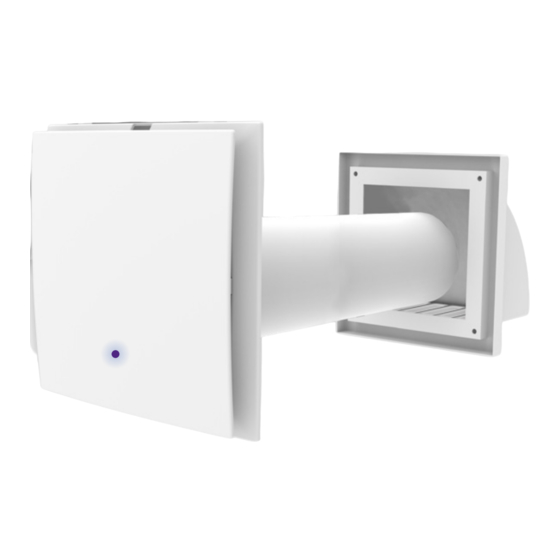
- Page 5 Sistemi FUNZIONAMENTO "PICO CLEAN WI 30 - 55 -80" L’aspiratore - estrattore si compone di un condotto dell’aria circolare a lunghezza fissa, unità di ventilazione e griglia esterna. I due motori ed il filtro si trovano all’interno del condotto. Il filtro è progettati per purificare l’aria di alimentazione e prevenire l’ingresso di oggetti estranei nell’aspiratore - estrattore e nelle ventole .
-
Page 6: Modalità Di Funzionamento
Sistemi MODALITÀ DI FUNZIONAMENTO N.B. Ad ogni funzione del recuperatore corrisponde una diversa colorazione del LED sul cruscotto. RECUPERATORE (Colore LED: azzurro) IL SISTEMA FUNZIONA PER 70 SECONDI IN ASPIRAZIONE E PER 70 SECONDI IN IMMISSIONE, CON LA POSSIBILITÀ DI REGOLARE LE TRE VELOCITÀ. -
Page 7: Utilizzo Del Telecomando
Sistemi UTILIZZO DEL TELECOMANDO Cambio Velocità Ventilatore ON RESET MANUTENZIONE FILTRI Tenere premuto per 3 secondi Impostazione valore di umidità Velocità massima (Valore umidità 60%) Ventilatore OFF Velocità media (Valore umidità 50%) Velocità minima RECUPERATORE (Valore umidità 40%) Il sistema funziona per 70 secondi in aspirazione e per 70 secondi in immissione, con la possibilità... - Page 8 Sistemi IMPOSTAZIONE DEL VALORE DI UMIDITÀ Per impostare il valore di umidità desiderato (40%, 50% o 60%) procedere nel modo seguente: • Selezionare, tramite il telecomando, la modalità AUTO 1 (led giallo) o AUTO 2 (led bianco). • Premere il tasto “ON”. •...
- Page 9 Sistemi OPERAZIONI PER LA CONNESSIONE, TRAMITE WI-FI, AL "PICO" DOTATO DI MODULO RADIO Regeneration Air Accendere il PICO. È sufficiente alimentare, elettricamente, PICO e lo stesso si avvierà (vedi immagine 1) automaticamente in modalità recupero. (luce led azzurra) Accendere alle impostazioni dello smartphone ed attivare la funzione WI-FI.
-
Page 10: Avvertenze Per Il Montaggio
Sistemi Alla fine della ricerca verra’ visualizzata la schermata di controllo principale. Questa schermata potrà essere aggiunta alla “schermata home” del telefono. Verra’ visualizzata l’icona qui sotto riportata: PICO CLEAN WI RECUPERATORE ESTRAZIONE IMMISSIONE Regeneration Air UMIDITÀ / AUTO 1 UMIDITÀ... - Page 11 Sistemi MONTAGGIO DEI RECUPERATORI PICO CLEAN WI 1) Installare il condotto nella parete, con inclinazione di 1° verso l’esterno. 1° 5 mm Preparare un foro circolare posizionato come visibile nella figura accanto Ø 103-128-153 - 204 2) Predisporre il cavo di alimentazione (vedi fig.1) avendo cura di farlo arrivare, Indifferentemente da destra o sinistra, nella parte superiore del condotto in corrispondenza del foro di condotto.
- Page 12 Sistemi 4) Allineare la ghiera a muro con il condotto dell’aria (vedi fig.2) fig.2 Ghiera a muro Condotto dell’aria 5) Fissare la ghiera praticando quattro fori sulla parete e utilizzando le quattro viti 4 x 30 e quattro tasselli incluse nella fornitura. (vedi fig.3) fig.3 6) Inserire l’assieme composto da motore e filtro.
- Page 13 Sistemi MONTAGGIO GRIGLIA DI ASPIRAZIONE RECUPERATORI Smontare la griglia esterna per consentire l’accesso ai fori di fissaggio. Togliere la parte superiore della griglia di ventilazione esterna. (vedi fig.1) DIMENSIONI (mm) MODELLO DIAMETRO (D) PICO CLEAN WI 30 PICO CLEAN WI 55 PICO CLEAN WI 80 fig.1 fig.2...
- Page 14 Sistemi Segnare i fori di fissaggio per la griglia di ventilazione esterna e forare. Per comodità usare la parte posteriore della griglia.(vedi fig.2) fig.2 Fissare la parte posteriore della griglia alla parete con viti 4x30 incluse. (vedi fig.3) fig.3 Montare la parte superiore della griglia. (vedi fig.4) fig.4...
-
Page 15: Collegamento Alla Rete
Sistemi COLLEGAMENTO ALLA RETE SCOLLEGARE IL RECUPERATORE DALL’ ALIMENTAZIONE PRIMA DI QUALSIASI OPERAZIONE DI MONTAGGIO ELETTRICO. COLLEGARE IL RECUPERATORE AD UNA PRESA INSTALLATA CORRETTAMENTE CON IL TERMINALE DI MESSA A TERRA. NON È CONSENTITA ALCUNA MODIFICA AI COLLEGAMENTI INTERNI, CHE PROVOCHEREBBE LA PERDITA DELLA GARANZIA Il recuperatore è... -
Page 16: Manutenzione
Sistemi MANUTENZIONE STACCARE IL VENTILATORE DALL’ALIMENTAZIONE DI RETE PRIMA DI INIZIARE LA MANUTENZIONE. Manutenzione del ventilatore significa pulizia regolare delle superfici del ventilatore dalla polvere e pulizia o sostituzione dei filtri. 1. Manutenzione ventole (una volta l’anno). Rimuovere l’unità ventilatore premendo simultaneamente sui due dentini di aggancio. - Page 17 Sistemi 2. Manutenzione rigeneratore e filtro (ogni 1500 ore). Togliere il filtro davanti al rigeneratore. Tirare il cordino del rigeneratore per togliere il rigeneratore dal condotto aria. Prestare attenzione quando si estrae il rigeneratore, per evitare danni. Togliere il filtro dopo il rigeneratore. Pulire il filtro quando si sporca (ogni 1500 ore).
-
Page 18: Ricerca Guasti
Sistemi RICERCA GUASTI Possibili cause Gestione dei guasti Controllare che il recuperatore sia collegato correttamente Alimentazione mancante. all’alimentazione di rete ed apportare eventuali correzioni se La ventola non parte necessario all’accensione del Spegnere il recuperatore. recuperatore. Risolvere il blocco motore e Il motore è... - Page 19 Air Curtains and Air Conditioning Accessories WI-FI Multi - Zone Air Control System Tecnosystemi S.p.A. via dell’Industria, 2/4 - Z.I. San Giacomo di Veglia 31029 Vittorio Veneto (Treviso) - Italy Phone +39 0438.500044 - Fax +39 0438.501516 email: info@tecnosystemi.com Instruments &...
-
Page 20: Safety Requirements
Multi - Zone Air Control System INTRODUCTION Instruments & Ventilation Tools Solutions This manual includes the technical description, operation, installation and assembly instructions, technical data for the intake-extractor unit “PICO CLEAN WI 30 - 55- 80”. Accessories For Heating SAFETY REQUIREMENTS Read the user manual carefully before use and installation of intake-extractor unit. -
Page 21: Assembly Warnings
Multi - Zone Air Control System ASSEMBLY WARNINGS Instruments & Ventilation Tools Solutions The recovery unit must not be used The recovery unit must be outside the temperature range, disconnected from the mains indicated in the user manual, supply before carrying out any or in aggressive or explosive Accessories installation or repair operation. - Page 22 Multi - Zone Air Control System DIMENSIONS "PICO CLEAN WI 30 - 55 -80" Instruments & Ventilation Tools Solutions Ø Accessories For Heating Ø DIMENSIONS AND MODELS (mm) (mm) (mm) (mm) (mm) (mm) (mm) ACD100025 / ACD100028 ACD100026 / ACD100029 ACD100027 / ACD100030 PICO CLEAN PICO CLEAN...
- Page 23 Multi - Zone Air Control System OPERATIONS OF "PICO CLEAN WI 30 - 55 -80" Instruments & Ventilation Tools Solutions The intake-extractor unit consists of a fixed length circular air duct, ventilation unit and external grille. Accessories For Heating The two motors and the filter are inside the duct. The filter has been designed to purify the supply air and to prevent foreign objects entering the intake-extractor unit and the fans.
-
Page 24: Operating Modes
Multi - Zone Air Control System OPERATING MODES Instruments & Ventilation Tools Solutions N.B. Every operation mode of the PICO corresponds to a different colour of the LED on the front cover. REGENERATOR (LED: light blue) Accessories For Heating THE DEVICE WORKS FOR 70 SECONDS IN EXTRACTION MODE AND 70 SECONDS IN AERATION MODE,... -
Page 25: Use Of Remote Control
Multi - Zone Air Control System USE OF REMOTE CONTROL Instruments & Ventilation Tools Solutions Accessories For Heating Change speed Fan ON RESET FILTER MAINTENANCE Press and hold for 3 seconds Humidity value setting Maximum speed (Humidity value 60%) Fan OFF Medium speed (Humidity value 50%) Low speed... - Page 26 Multi - Zone Air Control System SETTING THE HUMIDITY VALUE Instruments & Ventilation Tools Solutions To set the value of the desired humidity (40%, 50% or 60%) proceed as follows: • Using remote control, select AUTO 1 mode 1 (yellow LED) or AUTO 2 (white LED). Accessories For Heating •...
- Page 27 Multi - Zone Air Control System CONNECTION OPERATIONS BY MEANS OF WI-FI Instruments & Ventilation Tools TO THE “PICO” EQUIPPED WITH RADIO MODULE Solutions Regeneration Air To access PICO. It is sufficient to connect PICO to an electric source Accessories For Heating and it will turn on (see image 1) automatically in recovery mode.
- Page 28 Multi - Zone Air Control System At the end of this search the main control screen will be displayed. Instruments & Ventilation Tools Solutions This screen can be added to the telephone’s “home screen.” The icon shown below will be present: Accessories For Heating PICO CLEAN WI...
- Page 29 Multi - Zone Air Control System MOUNTING RECOVERY UNITS “PICO CLEAN WI" Instruments & Ventilation Tools Solutions 1) Install the duct in the wall, with a 1° inclination towards the outside. Accessories For Heating OUTSIDE INSIDE 1° 5 mm Prepare a circular hole positioned as shown in the adjacent figure Ø...
- Page 30 Multi - Zone Air Control System 4) Align the ring to the wall with the air duct (see pic. 2) Instruments & Ventilation Tools Solutions fig.2 Ghiera a muro Accessories For Heating Condotto dell’aria 5) Fix the ring making four holes in the wall and using the four 4x30 screws and the four dowels included in the supply.
- Page 31 Multi - Zone Air Control System ASSEMBLY OF THE RECOVERY UNIT INTAKE GRILLE Instruments & Ventilation Tools Solutions Remove the external grille in order to gain access to the fixing holes.. Remove the upper part of the external ventilation grille. (see pic. 1) Accessories For Heating DIMENSIONI (mm)
- Page 32 Multi - Zone Air Control System Mark the fixing holes for the external ventilation grille and drill. Instruments & Ventilation Tools For the sake of convenience, use the back part of the grille.(see pic.2) Solutions Accessories For Heating pic.2 Fix the back part of the grille to the wall with 4x30 screws included. (see pic. 3) pic.3 Assemble the upper part of the grille.
-
Page 33: Connection To The Mains
Multi - Zone Air Control System CONNECTION TO THE MAINS Instruments & Ventilation Tools Solutions BEFORE PERFORMING ANY ELECTRICAL ASSEMBLY OPERATION, DISCONNECT THE RECOVERY UNIT FROM THE MAINS. CONNECT THE RECOVERY UNIT TO A SOCKET INSTALLED CORRECTLY WITH THE GROUNDING TERMINAL. IT IS Accessories FORBIDDEN TO PERFORM ANY MODIFICATION TO THE INTERNAL CONNECTIONS For Heating... -
Page 34: Maintenance
Multi - Zone Air Control System MAINTENANCE Instruments & Ventilation Tools Solutions DISCONNECT THE FAN FROM THE MAINS SUPPLY BEFORE CARRYING OUT MAINTENANCE. Accessories For Heating Maintenance of the fan means regularly cleaning the surfaces of the fan from dust and cleaning or replacing the filters. - Page 35 Multi - Zone Air Control System 2. Maintenance of the regenerator and of the filter (every 1,500 hours). Instruments & Ventilation Tools Solutions Remove the filter in front of the regenerator. Pull the cord of the regenerator in order to remove the Accessories For Heating regenerator from the air duct.
-
Page 36: Troubleshooting
Multi - Zone Air Control System TROUBLESHOOTING Instruments & Ventilation Tools Solutions Possible causes Management of faults Accessories For Heating Check that the recovery unit is correctly connected to the No power supply. mains supply and connect it, if necessary. The fan does not start when the recovery unit is turned on. -
Page 37: Garanzia / Warranty
Multi - Zone Air Control System GARANZIA / WARRANTY Instruments & Ventilation Tools Solutions La garanzia ha durata di 2 anni a decorrere dalla data di consegna. L’azienda fornitrice garantisce la qualità dei materiali impiegati e la corretta realizzazione dei componenti. - Page 38 Multi - Zone Air Control System NOTE Instruments & Ventilation Tools Solutions Accessories For Heating...
- Page 39 Multi - Zone Air Control System NOTE Instruments & Ventilation Tools Solutions Accessories For Heating...
- Page 40 Air Control System Instruments & Ventilation Tools Solutions Tecnosystemi S.p.A. via dell’Industria, 2/4 - Z.I. San Giacomo di Veglia 31029 Vittorio Veneto (Treviso) - Italy Phone +39 0438.500044 Fax +39 0438.501516 email: info@tecnosystemi.com C.F. - P. IVA - R.I.TV IT02535780247 Cap. Soc. € 5.000.000,00 i.v.
Need help?
Do you have a question about the PICO CLEAN WI ACD100025 and is the answer not in the manual?
Questions and answers