Table of Contents
Advertisement
Available languages
Available languages
Quick Links
MANUALE D'USO
PICO BASIC, PICO PRO e PICO PRO +
Unità di ventilazione con recupero di calore
puntuale a parete
• cod. ACD100060
• cod. ACD100061
• cod. ACD100062
Tecnosystemi S.p.A. - Società Benefit
www.tecnosystemi.com
via dell'Industria, 2/4 - Z.I. San Giacomo di Veglia
31029 Vittorio Veneto (Treviso) - Italy
Phone +39 0438.500044 Fax +39 0438.501516
• cod. ACD100056
• cod. ACD100057
• cod. ACD100058
Numero Verde 800 904474
email: info@tecnosystemi.com
C.F. - P. IVA - R.I.TV IT02535780247 | Cap. Soc. € 5.000.000,00 i.v.
COD. CMU00123
REV. 00 / 02-04-2024
• cod. ACD100052
• cod. ACD100053
• cod. ACD100054
(only for Italy)
Advertisement
Chapters
Table of Contents

Related Manuals for Tecnosystemi Apply.co pico basic 30


Summary of Contents for Tecnosystemi Apply.co pico basic 30
- Page 1 • cod. ACD100057 • cod. ACD100053 • cod. ACD100062 • cod. ACD100058 • cod. ACD100054 Tecnosystemi S.p.A. - Società Benefit www.tecnosystemi.com via dell’Industria, 2/4 - Z.I. San Giacomo di Veglia Numero Verde 800 904474 (only for Italy) 31029 Vittorio Veneto (Treviso) - Italy email: info@tecnosystemi.com...
-
Page 2: Table Of Contents
5.1 Collegamenti elettrici 5.2 Procedura di installazione 6. Associazione e configurazione da Applicazione 7. Utilizzo del prodotto 7.1 Utilizzo tramite telecomando 7.2 Utilizzo via WiFi tramite Applicazione Tecnosystemi 7.3 Come creare un account con l’assistente vocale GOOGLE HOME 7.4 Come creare un account con l’assistente vocale AMAZON ALEXA 8. Collegamento di più dispositivi in cascata 8.1 Gestione MASTER / SLAVE con telecomando 9. Manutenzione ordinaria 9.1 Manutenzione filtri... -
Page 3: Introduzione
TECNOSYSTEMI SpA SOCIETÀ BENEFIT si impegna a migliorare e sviluppare continuamente i propri prodotti e si riserva il diritto di apportare modifiche alle specifiche, agli allestimenti e alla documentazione in qualsiasi momento, senza preavviso e senza obbligo di aggiornare le versioni già consegnate. Il presente manuale è scaricabile e disponibile sul sito web www.tecnosystemi.com oppure può essere richiesto all’indirizzo mail assistenza@tecnosystemi.com, indicando modello e serial number del prodotto. -
Page 4: Identificazione Dell'unità
1.5 Identificazione dell’unità Ogni prodotto è dotato di una etichetta fissata all’esterno dello stesso, che riporta i dati di identificazione della macchina e le principali caratteristiche tecniche. Verificare che le caratteristiche della rete elettrica siano conformi ai dati riportati sulla targhetta di identificazione. Un FACSIMILE dell’etichetta è rappresentato qui sotto con la relativa legenda dei dati in essa riportati: Modello e caratteristiche tecniche Codice EAN Codice seriale Grado IP L’etichetta identificativa non deve essere mai rimossa dal prodotto. -
Page 5: Sicurezza
2. Sicurezza 2.1 Avvertenze generali Questo manuale di istruzioni fornisce le informazioni essenziali per installare, utilizzare e mantenere il prodotto. È stato redatto in conformità alle normative dell’Unione Europea e alle norme tecniche in vigore al momento della pubblicazione. Questo manuale include le indicazioni per prevenire l’uso improprio del prodotto in modo ragionevolmente prevedibile. ATTENZIONE Per evitare danni alle persone e necessario assumere le seguenti precauzioni: • Qualsiasi operazione d’installazione e/o manutenzione del prodotto deve essere eseguita esclusivamente da personale professionalmente qualificato ed abilitato. • Questo apparecchio può essere utilizzato da bambini di età non inferiore a 8 anni e da persone con ridotte capacità fisiche, sensoriali o mentali o con esperienza e conoscenze insufficienti, purché attentamente sorvegliati e istruiti su come utilizzare in modo sicuro l’apparecchio e sui pericoli che ciò comporta. - Page 6 ATTENZIONE Per evitare danni al prodotto prendere le seguenti precauzioni: • Non apportare modifiche di alcun genere al prodotto. • Non coprire e non ostruire l’aspirazione e la mandata del prodotto, in modo da assicurare l’ottimale passaggio dell’aria. TECNOSYSTEMI S.p.A. SOCIETÀ BENEFIT declina ogni responsabilità per eventuali danni causati da una non corretta installazione, uso improprio o manomissione del prodotto.
-
Page 7: Descrizione Del Prodotto
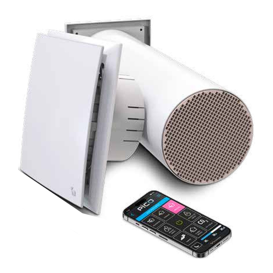
Grazie al suo sistema di ventilazione integrata ad alto rendimento, che può recuperare fino al 90% del calore, PICO si distingue per la sua efficacia. Questo è reso possibile grazie allo scambiatore di calore a struttura alveolare in materiale ceramico, che massimizza l’efficienza termica. Inoltre, l’installazione di PICO è semplice e la sua manutenzione richiede poco sforzo. Questo non solo semplifica la gestione complessiva del sistema, ma anche riduce i costi di manutenzione nel lungo periodo. Il PICO integra un sistema di comunicazione WIFI che permette l’utilizzo del dispositivo mediante controllo remoto o locale tramite app Tecnosystemi. GRIGLIA ESTERNA SERRANDA MECCANICA ALIMENTAZIONE 230V PACCO DI SCAMBIO FRONTALE ESTETICO LED RGB MODALITÀ... -
Page 8: Caratteristiche Tecniche
3.2 Caratteristiche tecniche • Dimensioni Le funzionalità del prodotto si differenziano per modello acquistato. Per maggiori informazioni sulle funzionalità disponibili vedere la tabella relativa. Ø PESO MODELLI [mm] [mm] [mm] [mm] [mm] [mm] [kg] PICO 30 PICO 45 PICO 60 • Dati targa Alimentazione elettrica 90-240V +/- 10%, 50/60 Hz Classe di isolamento Grado IP IPX4 Tipologia di installazione Fisso Telecomando Controllo... - Page 9 • Dati tecnici - PICO BASIC PICO BASIC 30 Standby NIGHT Velocità minima Velocità media Velocità massima Modalità Estrazione Immissione Estrazione Immissione Estrazione Immissione Estrazione Immissione Consumo [W] <1 Portata aria [m³/h] Pressione sonora @2m [dB(A)] Classe Energetica SEC Tipologia UVR Bidirezionale Tipo sistema di recupero Rigenerativo tipo HRC3b...
- Page 10 • Dati tecnici - PICO PRO PICO PRO 30 Standby NIGHT Velocità minima Velocità media Velocità massima Modalità Estrazione Immissione Estrazione Immissione Estrazione Immissione Estrazione Immissione Consumo [W] <1 Portata aria [m³/h] Pressione sonora @2m [dB(A)] Classe Energetica SEC Tipologia UVR Bidirezionale Tipo sistema di recupero Rigenerativo tipo HRC3b...
- Page 11 • Dati tecnici - PICO PRO + PICO PRO 30 + Standby NIGHT Velocità minima Velocità media Velocità massima Modalità Estrazione Immissione Estrazione Immissione Estrazione Immissione Estrazione Immissione Consumo [W] <1 Portata aria [m³/h] Pressione sonora @2m [dB(A)] Classe Energetica SEC Tipologia UVR Bidirezionale Tipo sistema di recupero...
-
Page 12: Contenuto Della Confezione / Accessori
3.3 Contenuto della confezione / Accessori Il pacchetto include i seguenti elementi. Si prega di controllare all’apertura della confezione la presenza di: n°1 unità ventilante n° 1 pacco di scambio n°1 supporto a muro n°1 condotto in PVC con filtri PICO BASIC 30 30 m ENERGIA · · ΕΝΕΡΓΕΙΑ · ENERGIJA · ENERGY · ENERGIE · ENERGI 2016 1254/2014 n°... -
Page 13: Trasporto, Movimentazione E Stoccaggio
4. Trasporto, movimentazione e stoccaggio 4.1 Ricevimento e ispezione Il prodotto è fornito di fabbrica imballato ed in perfetto stato. Al momento del ricevimento del prodotto verificarne l’integrità: eventuali danni dovranno essere immediatamente contestati al trasportatore annotandoli sul documento di trasporto e informando tempestivamente il fornitore. 4.2 Stoccaggio Conservare il prodotto imballato nel proprio imballaggio, in un luogo chiuso e asciutto e al riparo dagli agenti atmosferici. -
Page 14: Installazione E Messa In Servizio
5. Installazione ATTENZIONE • L’installazione e la prima messa in servizio deve essere eseguita esclusivamente da personale professionalmente qualificato ed abilitato • Durante tutte le procedure di installazione, assicurarsi che l’apparecchiatura non sia collegata alla rete elettrica. • Il dispositivo non deve essere installato all’interno di locali adibiti a bagno e/o lavanderia. • Il dispositivo non è canalizzabile. Durante l’installazione o quando si deve intervenire sul prodotto, è necessario seguire attentamente le norme riportate nel manuale, rispettare le indicazioni sul prodotto stesso e adottare tutte le precauzioni necessarie. La mancata osservanza delle norme può causare situazioni di pericolo. -
Page 15: Procedura Di Installazione
5.2 Procedura di installazione ATTENZIONE Il dispositivo di ventilazione deve essere installato all’interno della parete, mentre la griglia esterna deve essere posizionata sul lato esterno al fine di evitare l’ingresso di acqua e altri oggetti, nel dispositivo stesso. Per un funzionamento corretto e sicuro del prodotto, rispettare le distanze minime di installazione di seguito descritte. - Page 16 2. Predisporre l’alimentazione mediante guaina di tipo elettrico, da installare sotto traccia o canalina elettrica idonea a contenere il cavo di alimentazione. Il cavo di alimentazione deve uscire da uno dei 4 punti indicati in figura, in una posizione comoda e che non interferisca con la ghiera di montaggio e con il dispositivo stesso. 1 0 0 ÷ 1 1 3. Installare il condotto nella parete, con inclinazione di 1° verso l’esterno. Il condotto aria deve essere a filo parete interna e sporgere dal muro esterno di 5 mm circa. Riempire gli spazi tra la parete e il condotto con silicone, schiuma o altro materiale idoneo.
- Page 17 5. Praticare 4 fori sulla parete e posizionare i 4 tasselli forniti nel kit. Ø8x4 6. Effettuare i collegamenti elettrici al morsetto di alimentazione, e fissare il cavo di alimentazione con il fermacavo come da immagine. PARTICOLARE DEL FERMACAVO 230 V~...
- Page 18 7. Posizionare il supportoa muro e fissarlo con le 4 viti in dotazione avendo cura di centrarlo con il condotto. 8. Posizionare la griglia esterna a muro avendo cura di centrarla con il condotto e segnare i 4 punti di fissaggio.
- Page 19 9. Inserire nel condotto il pacco [P] di scambio ceramico fino in fondo, come indicato in figura. 10. Inserire e agganciare il dispostistivo di ventilazione. click click...
-
Page 20: Associazione E Configurazione Da Applicazione
6. Associazione e configurazione da Applicazione Il PICO BASIC deve essere configurato entro 2 min dall’accensione, pertanto si consiglia di scaricare preventiva- mente l’App TECNOSYSTEMI da La modalità di configurazione si attiva alla prima accensione del dispositivo. La seguente procedura vale per tutti i modelli di PICO. Le procedure che differiscono da modello a modello sono evidenziate durante la configurazione. Scaricare l’App TECNOSYSTEMI •• •• • • • • • • • • • • 2. A ccedere all’applicazione e registrare i propri dati o • • •• • •• • • • • • • • • • • • •• • • • ••••••••• • • • •• •••••••... - Page 21 4. Scegliere il tipo di dispositivo da aggiungere all’impianto e il tipo di connessione: • connessione OFFLINE; • connessione ONLINE. Funzionamento Offline In questa modalità il dispositivo o il sistema di dispositivi vengono installati in una casa senza accesso a Internet. Funzionamento Online In questa modalità il dispositivo o il sistema di dispositivi vengono installati in una casa con accesso a Internet. 5. Dare alimentazione al dispositivo.
- Page 22 Per i modelli PICO BASIC La modalità di configurazione viene attivata entro 2 minuti dalla prima alimentazione. In questa fase il LED BLU lampeggia. Se la configurazione non è avvenuta entro i 2 minuti, disconnettere alimentazione, attendere 5 s e riconnettere dispositivo. a. Premere PROCEDI. Per i modelli PICO PRO e PICO PRO+ b. Accendere il dispositivo. c. Avvicinare il telecomando al dispositivo e premere contemporaneamente i tasti NIGHT e VELOCITÀ MINIMA per almeno 3 s. Il LED BLU del dispositivo lampeggia. d. Premere PROCEDI. 6. Verificare la correttezza di connessione con il dispositivo, verificando lo stato del LED. Premere VERIFICA LED. 8. Se la connessione è stabilita correttamente il LED verde si accende. 9. Digitare il nome del dispositivo installato. 10. Digitare un codice di sicurezza di 4 cifre (esempio: 1234).
- Page 23 MODALITÀ ONLINE a. Selezionare la rete WiFi da utilizzare. Se la rete desiderata non appare nell’elenco premere AGGIORNA. b. Inserire la Password della rete. c. Attendere termine della configurazione. d. Premere FINE. Configurare tutti i PICO installati. È possibile configurare ogni PICO installato all’interno di un sistema di dispositivi, come MASTER o come SLAVE. Per configurare più dispositivi in modalità master slave fare riferimento al capitolo: Collegamento di più...
-
Page 24: Utilizzo Del Prodotto
7. Utilizzo del prodotto Prima dell’uso mediante il telecomando o dell’App Tecnosystemi, controllare che il dispositivo sia correttamente fissato a parete. Non collocare oggetti sopra o sotto il dispositivo, in modo da non impedire il flusso d’aria. I dispositivi PICO PRO e PICO PRO+ alla prima alimentazione sono pronti per il funzionamento mediante telecomando. I PICO BASIC devono essere configurati entro 2 minuti dall’accensione mediante la APP Tecnosystemi. - Page 25 FUNZIONE DESCRIZIONE La funzione attiva la modalità RECUPERO. Il recupero del calore avviene mediante l’alternanza del flusso in immissione (70 s) ed estrazione (70 s). Recupero La funzione permette la regolazione delle tre velocità disponibili. Funzione di default: Alla prima attivazione il dispositivo è impostato in modalità recuperatore e la velocità è media. La funzione attiva la modalità ESTRAZIONE. Estrazione La funzione permette la regolazione delle tre velocità disponibili. In questa modalità il livello di umidità e di CO non viene considerato. La funzione attiva la modalità IMMISSIONE. Immissione La funzione permette la regolazione delle tre velocità disponibili. In questa modalità il livello di umidità e di CO non viene considerato. Il sistema monitora l’umidità dell’ambiente interno. Quando l’aria nell’ambiente supera la soglia di umidità impostata, il dispositivo si attiva in funzione di RECUPERO fino a riportare l’umidità entro il valore richiesto. Per rilevare l’umidità della stanza interna viene attivata la ventilazione in ESTRAZIONE alla ve- locità minima. Al superamento della soglia di umidità il recuperatore passa in modalità RECUPERO alla velo- cità massima. Al ripristino del valore di umidità il dispositivo ritorna in modalità ESTRAZIONE alla velocità Recupero minima.
- Page 26 FUNZIONE DESCRIZIONE Il sistema monitora l’umidità dell’ambiente. Quando l’aria nell’ambiente supera la soglia di umidità, il dispositivo si attiva in funzione di sola ESTRAZIONE fino a riportare l’umidità entro il valore richiesto. Per rilevare l’umidità della stanza interna viene attivata la ventilazione in ESTRAZIONE alla ve- locità minima. Al superamento della soglia di umidità il recuperatore passa in modalità ESTRAZIONE alla velocità massima. Al ripristino del valore di umidità il dispositivo ritorna in modalità ESTRAZIONE alla velocità minima. Estrazione con soglia umidità Il valore di umidità impostato di fabbrica è del 50%.
- Page 27 FUNZIONE DESCRIZIONE Disponibile solo nei modelli PICO PRO+ Il sistema monitora la concentrazione di CO presente nell’ambiente interno. Quando la concentrazione supera la soglia di 800 ppm, il dispositivo si attiva in funzione di Recupero con RECUPERO alla velocità MASSIMA. soglia CO Al ripristino del valore di CO il dispositivo ritorna in modalità RECUPERO alla velocità MINIMA. ATTENZIONE: Si sconsiglia la selezione di questa modalità con condizioni di inquina- mento elevato all’esterno dell’edificio.
-
Page 28: Utilizzo Tramite Telecomando
7.1 Utilizzo tramite telecomando Le funzioni del telecomando sono selezionabili mediante il tasto MODE. La modalità di riferimento è identificata dall’accensione dal corrispettivo LED colorato (esempio AUTO1 = LED giallo). Le funzioni del telecomando disponibili dipendono dal tipo di modello di PICO acquistato. Il telecomando è fornito di serie nei modelli PICO PRO e PICO PRO+. È acquistabile separatamente nei modelli PICO BASIC. AUTO2 AUTO1 FUNZIONE DESCRIZIONE La pressione del tasto permette di accendere o spegnere il dispositivo. Accesione All’accensione del telecomando (ON) il LED rosso sul telecomando si / Spegnimento accende. Recupero Premere il tasto MODE fino all’accensione del LED azzurro. Estrazione Premere il tasto MODE fino all’accensione del LED verde. Immissione Premere il tasto MODE fino all’accensione del LED fuxia. Recupero Premere il tasto MODE fino all’accensione del LED giallo. con soglia umidità Estrazione Premere il tasto MODE fino all’accensione del LED bianco. con soglia umidità... - Page 29 FUNZIONE DESCRIZIONE Disponibile solo nei modelli PICO PRO+ Free cooling Premere il tasto MODE fino all’accensione del LED arancione. Disponibile solo nei modelli PICO PRO+ Free heating Premere il tasto MODE fino all’accensione del LED arancione. Disponibile solo nei modelli PICO PRO+ Recupero con soglia CO Premere il tasto MODE fino all’accensione del LED blu medio. Disponibile solo nei modelli PICO PRO+ Estrazione con soglia CO Premere il tasto MODE fino all’accensione del LED blu intenso.
- Page 30 • Funzioni addizionali L’accesso alle seguenti funzione è data dalla pressione prolungata di alcuni tasti o dalla combinazione di uno o più di essi. FUNZIONE DESCRIZIONE Quando il dispositivo raggiunge 1500 ore di funzionamento il LED rosso lampeggia (2 s ON - 2 s OFF) ad indicare la necessità di pulire i filtri. Procedere a lla p ulizia d ei fi ltri c ome i ndicato a l C apitolo Manutenzione. Spegnere il dispositivo premendo il tasto Reset Manutenzione filtri Per azzerare il contatore premere e tenere premuto il tasto almeno 6 s.
-
Page 31: Utilizzo Via Wifi Tramite Applicazione Tecnosystemi
7.2 Utilizzo via WiFi tramite Applicazione Tecnosystemi Le funzioni disponibili sull’App dipendono dal tipo di modello di PICO acquistato. Se il modello non prevede determinate funzioni queste non saranno visibili sull’Applicazione. MENU IMPOSTAZIONI TASTI FUNZIONE SLIDER VELOCITÀ MODALITÀ NOTTE VENTILAZIONE FUNZIONE DESCRIZIONE Recupero La funzione attiva la modalità RECUPERO. Estrazione La funzione attiva la modalità ESTRAZIONE. Immissione La funzione attiva la modalità IMMISSIONE. Recupero La funzione attiva la modalità RECUPERO CON SOGLIA DI UMIDITÀ. con soglia umidità Estrazione La funzione attiva la modalità ESTRAZIONE CON SOGLIA DI UMIDITÀ. con soglia umidità Disponibile solo nei modelli PICO PRO+ Free cooling La funzione attiva la modalità FREE COOLING. - Page 32 FUNZIONE DESCRIZIONE Disponibile solo nei modelli PICO PRO+ Free heating La funzione attiva la modalità FREE HEATING. Disponibile solo nei modelli PICO PRO+ Recupero con soglia CO La funzione attiva la modalità RECUPERO CON SOGLIA CO Disponibile solo nei modelli PICO PRO+ Estrazione con soglia CO La funzione attiva la modalità ESTRAZIONE CON SOGLIA CO Disponibile solo nei modelli PICO PRO+ Recupero con soglia umidità...
- Page 33 • Menu Impostazioni Questo menu permette la configurazione e l’impostazione di alcune funzioni del dispositivo. Per accedere al menu impostazioni premere FUNZIONE DESCRIZIONE Rinomina Questa funzione permette di modifica il nome del dispositivo Questa funzione NON permette di modificare il PIN ma per effettuare Modifica PIN questa procedura sarà necessario ri-configurare il dispositivo. Questa funzione permette di verificare la versione FW del dispositivo e Verifica FW gli eventuali aggiornamenti disponibii. Per aggiornare la centralina all’ultimo FIRMWARE disponibile accedere Aggiornamento FW al menu AGGIORNAMENTO FIRMWARE e avviare la procedura. Seguire le indicazioni fornite dall’App e concludere la procedura. Questa funzione permette di gestire la configurazione dei dispositivi SLAVE rispetto al dispositivo MASTER.
-
Page 34: Come Creare Un Account Con L'assistente Vocale Google Home
9. Quando si conclude la configurazione, nella Home dell’Applicazione TECNOSYSTEMI sono disponibili tutti i dispositivi associati. 10. Il nome dei dispositivi è lo stesso assegnato nell’Applicazione TECNOSYSTEMI. COSA FARE CON L’ASSISTENTE VOCALE GOOGLE HOME: Con l’App di GOOGLE HOME è possibile accendere o spegnere l’impianto, regolare la temperatura dei termo- stati di zona, nonché l’accensione o lo spegnimento dei dispositivi PICO. Tra le funzioni che gestische l’assistente vocale è possibile impostare: • “Ok Google, accendi (nome PICO)” • “Ok Google, Spegni (nome PICO)” ATTENZIONE Prima di collegare l’assistente vocale, leggete bene le istruzioni del dispositivo “Google HOME”. Tecnosystemi S.p.A. Società Benefit si solleva da ogni eventuale responsabilità di mancato funzionamento dell’app o del dispositivo. -
Page 35: Come Creare Un Account Con L'assistente Vocale Amazon Alexa
COSA FARE CON L’ASSISTENTE VOCALE AMAZON ALEXA: Con l’App di AMAZON ALEXA è possibile accendere o spegnere l’impianto, regolare la temperatura dei termo- stati di zona, nonché l’accensione o lo spegnimento dei dispositivi PICO. Tra le funzioni che gestische l’assistente vocale è possibile impostare: • “Alexa, accendi (nome PICO)” • “Alexa, Spegni (nome PICO)” ATTENZIONE Prima di collegare l’assistente vocale, leggete bene le istruzioni del dispositivo “AMAZON ALEXA”. Tecnosystemi S.p.A. Società Benefit si solleva da ogni eventuale responsabilità di mancato funzionamento dell’app o del dispositivo. -
Page 36: Collegamento Di Più Dispositivi In Cascata
8. Collegamento di più dispositivi in cascata È possibile gestire più dispositivi contemporaneamente creando una rete MASTER / SLAVE tramite la modalità cascata. Una volta configurato il primo dispositivo detto “MASTER” è possibile procedere ad associare ad esso fino a quattro dispositivi subordinati detti “SLAVE”. La gestione e la comunicazione tra il dispositivo MASTER e quelli SLAVE avviene via rete WiFi. Ogni singolo SLAVE può essere configurato per funzionare in modalità SINCRONA o ASINCRONA rispetto al dispositivo MASTER. -
Page 37: Gestione Master / Slave Con Telecomando
8.1 Gestione MASTER / SLAVE con telecomando MASTER MASTER SLAVE1 SLAVE1 SLAVE2 SLAVE2 SLAVE3 SLAVE3 SLAVE4 SLAVE4 Se il telecomando viene indirizzato verso il dispositivo Se il telecomando viene indirizzato verso uno SLAVE, MASTER, il dispositivo esegue il comando e ripartisce il comando inviato viene prima trasmesso al disposi- le informazioni a tutti i dispositivi SLAVE. tivo MASTER per poi essere ripartito a tutti i dispositivi SLAVE. -
Page 38: Manutenzione Ordinaria
9. Manutenzione Ordinaria ATTENZIONE Le operazioni di messa in servizio devono essere eseguite in conformità a tutte le prescrizioni dei paragrafi precedenti. Tutte le operazioni effettuate sulla macchina devono essere eseguite da personale abilitato, in ottemperanza alla legislazione nazionale vigente nel paese di destinazione. Prima di eseguire qualsiasi intervento sul dispositivo o di accedere alle sue parti interne, è fondamentale assicurarsi di aver disconnesso l’alimentazione elettrica. 9.1 Pulizia o sostituzione dei Filtri I filtri sporchi causano un aumento della perdita di carico del dispositivo e una riduzione del volume dell’aria. -
Page 39: Manutenzione Del Pacco Di Scambio
9.2 Pulizia del pacco di scambio Si raccomanda di verificare occasionalmente lo stato dello scambiatore di calore. Questa operazione deve essere eseguita esclusivamente da personale qualificato. Procedere come segue: 1. Disconnetere l’alimentazione del dispositivo. 2. Sganciare il coperchio dal dispositivo premendo sulle alette laterali ed estrarre il corpo ventilante. 3. Estrarre il pacco di scambio verso l’interno con estrema cautela. 4. Pulire il pacco di scambio delicatamente utilizzando un’aspirapolvere o un compressore. 5. Reinserire il pacco di scambio nella sua sede fino in fondo 6. Rimontare il corpo ventilante rispettando il verso di installazione. 9.3 Manutenzione griglia esterna La griglia esterna di ventilazione si può intasare con foglie o altri oggetti che impediscono il buon funzionamento del dispositivo. Controllare la griglia di ventilazione due volte l’anno e pulirla ogniqualvolta sia necessario. -
Page 40: Diagnosi E Risoluzione Dei Problemi
10. Diagnosi e risoluzione dei problemi Problema Possibile causa Soluzione Controllare che il dispositivo sia Mancanza di alimentazione collegato correttamente all’alimentazione di rete La ventola non parte Malfunzionamento del’unità di Verificare l’unità di comando e la sua comando del dispositivo. alimentazione Collegamenti elettrici errati Verificare l’attivazione del LED Verificare che la ventola non sia Ventola in protezione bloccata da oggetti esterni Verificare la presenza di oggetti Le pale della ventola sono ostruite esterni ed eventualmente rimuoverli Verificare i collegamenti elettrici e La ventola si arresta inaspettatamente... -
Page 41: Smaltimento
11. Disassemblaggio e smaltimento Tutte le operazioni di messa fuori servizio devono essere eseguite da personale abilitato in ottemperanza alla legislazione nazionale. Lo smaltimento deve avvenire in accordo alla Direttiva 2012/19/UE sui Rifiuti da Apparecchiature Elettrici ed Elettronici (RAEE). Il simbolo del cassonetto barrato riportato sull’apparecchio indica che il prodotto, alla fine della propria vita utile, deve essere trattato separatamente dai rifiuti domestici. Il prodotto deve essere conferito in un centro di raccolta differenziata per apparecchiature elettriche ed elettroniche oppure riconsegnato al rivenditore al momento dell’acquisto di una nuova apparecchiatura equivalente. -
Page 42: Garanzia
12. Garanzia 1. La presente garanzia opera esclusivamente nei confronti del Cliente (persona giuridica) e non nei confronti del consumatore finale (persona fisica) al quale il Cliente abbia fornito il Prodotto. 2. La garanzia ha durata di anni 2 (due) a decorrere dalla data di consegna indicata sul d.d.t (bolla). 3. La garanzia copre i difetti di fabbricazione e del materiale dei Prodotti. Non opererà dunque con riferimento ai difetti causati da: • trasporto non idoneo; • uso negligente o improprio del singolo Prodotto e comunque non conforme a quanto specificato nelle istruzioni e/o manuali d’installazione, uso e manutenzione, laddove previsti; • non osservanza delle specifiche tecniche di Prodotto; • riparazioni o modifiche apportate dal Cliente o da terzi, senza la preventiva autorizzazione scritta del Fornitore; • anomalie causate da e/o connesse a parti assemblate/aggiunte direttamente dal Cliente; • mancata o non idonea manutenzione; • quant’altro non riconducibile a vizi originari del materiale o di produzione. 4. Per i Prodotti coperti da garanzia, il Fornitore procederà con la sostituzione o riparazione del Prodotto o delle parti di esso che presentino vizi o difetti, previa valutazione discrezionale in merito all’esistenza dei vizi o difetti. - Page 43 • Code ACD100061 • Code ACD100057 • Code ACD100053 • Code ACD100062 • Code ACD100058 • Code ACD100054 Tecnosystemi S.p.A. - Società Benefit www.tecnosystemi.com Freephone number 800 904474 (only for Italy) via dell’Industria, 2/4 - Z.I. San Giacomo di Veglia email: info@tecnosystemi.com Tax Code - VAT number - R.I.TV IT02535780247 |...
- Page 44 5. Installation and commissioning 5.1 Electrical connections 5.2 Installation procedure 6. Pairing and configuration from Application 7. Using the product 7.1 Use with remote control 7.2 Use via WiFi with Tecnosystemi Application 7.3 How to create an account with GOOGLE HOME voice assistant 7.4 How to create an account with AMAZON ALEXA voice assistant 8. Cascade connection of several devices 8.1 MASTER / SLAVE management with remote control 9. Routine maintenance 9.1 Filter maintenance 9.2 Exchange pack maintenance...
-
Page 45: Introduction
1.4 Updated instructions Verify whether the instructions are up to date with the latest revision available. TECNOSYSTEMI SpA SOCIETÀ BENEFIT is committed to continuously improving and developing its products and reserves the right to make changes to specifications, installations and documentation at any time, without notice and without obligation to update the versions already delivered. This manual can be downloaded from and it is available on the website www.tecnosystemi.com or can be requested through the email address assistenza@tecnosystemi.com, indicating the model and serial number of the product. -
Page 46: Identification Of The Unit
1.5 Identification of the unit Each product comes with a label fixed to the external of the product, bearing the identification data of the machine and the main technical characteristics. Check that the characteristics of the electrical network comply with the data shown on the identification plate. A FACSIMILE of the label is shown below with the relevant key of the data contained therein: Model and technical characteristics EAN code Serial number IP Grade Do not remove the identification label from the product for any reason whatsoever. -
Page 47: Safety
2. Safety 2.1 General warnings This instructions manual provides information essential for the installation, use and maintenance of the product. It was drawn up in accordance with European Union legislation and technical standards in force at the time of publication. This manual includes guidance to prevent improper use of the product in a reasonably foreseeable manner. - Page 48 • Do not cover or obstruct the intake and delivery of the product so as to ensure optimum air flow. TECNOSYSTEMI S.p.A. SOCIETÀ BENEFIT shall not be held liable for any damage stemming from improper installation, improper use or tampering with the product.
-
Page 49: Product Description
Thanks to its integrated high efficiency ventilation system, which can recover up to 90% of the heat, PICO stands out for its effectiveness. This is obtained through a heat exchanger with a honeycomb structure made of ceramic material, which maximises thermal efficiency. Furthermore, PICO is easy to install and its maintenance requires little effort. This not only simplifies overall system management, but also reduces maintenance costs in the long term. PICO comes with a built-in a WIFI communication system which allows the use of the device via remote or local control using the Tecnosystemi app. EXTERNAL GRILLE MECHANICAL DAMPER POWER SUPPLY 230 V EXCHANGE PACK AESTHETIC... -
Page 50: Technical Characteristics
3.2 Technical characteristics • Dimensions Product functions differ by model purchased. For further information on the available functions, see the related table. Ø WEIGHT MODELS [mm] [mm] [mm] [mm] [mm] [mm] [kg] PICO 30 PICO 45 PICO 60 • Identification plate data Power supply 90-240V +/- 10%, 50/60 Hz Insulation class... - Page 51 • Technical data - PICO BASIC PICO BASIC 30 Standby NIGHT Minimum speed Average speed Maximum speed Mode Extraction Ventilation Extraction Ventilation Extraction Ventilation Extraction Ventilation Consumption [W] <1 Air flow rate [m³/h] Sound pressure @2m [dB(A)] SEC Energy Class Type UVR Dual Flow Type of heat recovery unit...
- Page 52 • Technical data - PICO PRO PICO PRO 30 Standby NIGHT Minimum speed Average speed Maximum speed Mode Extraction Ventilation Extraction Ventilation Extraction Ventilation Extraction Ventilation Consumption [W] <1 Air flow rate [m³/h] Sound pressure @2m [dB(A)] SEC Energy Class Type UVR Dual Flow Type of heat recovery unit...
- Page 53 • Technical data - PICO PRO + PICO PRO 30 + Standby NIGHT Minimum speed Average speed Maximum speed Mode Extraction Ventilation Extraction Ventilation Extraction Ventilation Extraction Ventilation Consumption [W] <1 Air flow rate [m³/h] Sound pressure @2m [dB(A)] SEC Energy Class Type UVR Dual Flow Type of heat recovery unit...
-
Page 54: Package Content / Accessories
3.3 Packaging content / Accessories The package includes the following items. Please check when opening the package that the following are included: 1 ventilation unit 1 exchange pack 1 wall mount 1 PVC duct with filters PICO BASIC 30 30 m ENERGIA · · ΕΝΕΡΓΕΙΑ · ENERGIJA · ENERGY · ENERGIE · ENERGI 2016 1254/2014 1 external grille Screw and dowel kit 1 remote control... -
Page 55: Transportation, Handling And Storage
4. Transportation, handling and storage 4.1 Receipt and inspection The product is supplied factory packaged and in perfect condition. Upon receipt of the product, verify whether it is intact: any damage must be promptly reported to the carrier by noting it on the transportation document and promptly notifying the supplier. 4.2 Storage Store the packaged product in its packaging in a closed and dry place, away from atmospheric agents. -
Page 56: Installation And Commissioning
5. Installation ATTENTION • Installation and first commissioning shall be carried out only by professionally qualified and approved staff • During all installation procedures, make sure that the equipment is not connected to the mains. • The device shall not be installed in bathrooms and/or laundry rooms. • The device cannot be ducted. During installation or when servicing the product, you must carefully follow the rules indicated in the manual, observe the instructions on the product, and take all necessary precautions. -
Page 57: Installation Procedure
5.2 Installation procedure ATTENTION The ventilation device shall be installed inside the wall, while the external grille shall be placed on the outer side so as to prevent water and other objects from entering into the device. Observe the minimum installation distances described below for proper and safe operation of the product. 300 mm 300 mm Provide a circular hole passing through the wall, having dimensions suitable to allow the positioning of the duct delivered with the purchased device (*). - Page 58 2. Provision of power supply by means of an electrical sheath, to be installed underground or cable raceway suitable to hold the power supply cable. The power supply cable should be routed from one of the 4 points shown in the illustration, in a convenient position that does not interfere with the assembly ring nut and the device.
- Page 59 5. Drill 4 holes on the wall and place the 4 dowels supplied in the kit. Ø8x4 6. Carry out electrical connections to the power terminal, and secure the power supply cable with the cable tie as shown in the image. DETAIL OF THE CABLE TIE 230 V~...
- Page 60 Position the wall mount and secure it with the 4 screws provided, making sure to centre it with the duct. 8. Position the wall-mounted external grille making sure to centre it with the duct and mark the 4 fixing points.
- Page 61 9. Insert the ceramic exchange pack [P] fully into the duct as shown in the illustration. 10. Insert and attach the ventilation device. click click...
-
Page 62: Pairing And Configuration From Application
6. Pairing and configuration from Application PICO BASIC shall be configured within 2 mins from the power-up. Therefore, it is recommended to download the TECNOSYSTEMI App in advance from Configuration mode is enabled when the device is turned on for the first time. The following procedure applies to all PICO models. Procedures that differ from model to model are highlighted during configuration. Download the TECNOSYSTEMI app from •• •• • • • • • • • • • • 2. Log in to the application and register your details or • • •• • •• • • • • • • • • • • • •• • • • ••••••••• • • • •• •••••••... - Page 63 4. Choose the type of device to be added to the installation and the type of connection: • OFFLINE connection; • ONLINE connection. Offline operation In this mode, the device or device system are installed in a home without Internet access. Online operation In this mode, the device or device system is installed in a home with Internet access. 5.
- Page 64 For PICO BASIC models Configuration mode is enabled within 2 minutes of the first power supply. The BLUE LED blinks in this stage. Should the configuration not be successful within 2 minutes, disconnect the power supply, wait 5 s, and reconnect the device. a. Press PROCEED. For PICO PRO and PICO PRO+ models b. Turn on the device. c. Move the remote control closer to the device and press the NIGHT and MINIMUM SPEED keys at the same time for at least 3 s. The BLUE LED on the device blinks. d. Press PROCEED. 6. Check for the correct connection with the device, by checking the status of the LED. Press CHECK LED.
- Page 65 ONLINE MODE a. Select the Wi-Fi network to be used. Should the desired network not appear in the list, press UPDATE. b. Enter the network password. c. Wait for configuration to complete. d. Press END. Configure all installed PICOs. Each PICO installed within a device system can be configured, either as a MASTER or as a SLAVE. To configure multiple devices in slave master mode reference shall be made to chapter: Cascade connection of several devices...
-
Page 66: Using The Product
At the first power supply, the PICO PRO and PICO PRO+ devices are ready for operation with remote control. PICO BASIC shall be configured within 2 minutes of being turned on using the Tecnosystemi APP. For further information, please refer to the Configuration chapter. - Page 67 FUNCTION DESCRIPTION The function enables the RECOVERY mode. Heat recovery is achieved by alternating the introduction (70 s) and removal (70 s) flow. Recovery The function allows to adjust the three available speeds. Default function: Upon first activation, the device is set to recovery mode and the speed is medium. The function enables the REMOVAL mode. Removal The function allows to adjust the three available speeds. Humidity and CO level are not considered in this mode . The function enables the INTRODUCTION mode. Introduction The function allows to adjust the three available speeds. Humidity and CO level are not considered in this mode .
- Page 68 FUNCTION DESCRIPTION The system monitors the humidity in the environment. When the ambient air exceeds the humidity threshold, the device is enabled as a REMOVAL-only function until the humidity returns to the required value. To detect humidity of the internal room, REMOVAL ventilation is enabled at minimum speed. Upon exceeding the humidity threshold, the recovery device switches to REMOVAL mode at maximum speed. Upon reset of the humidity value, the device resumes the REMOVAL mode at minimum speed. Removal with humidity The factory set moisture value is 50%. threshold To change the desired humidity threshold (40%, 50% or 60%) to enable the function, use the speed keys: MINIMUM speed / 1 LED blink/Set level 40%; MEDIUM speed / 2 LED blinks/ Set level 50%; MAXIMUM speed / 3 LED blinks/ Set level 60%. Upon completion of this operation, the white LED remains fixed to confirm that the selected humidity value has been correctly set. Available on PICO PRO+ models only Upon activating the FREE COOLING function, the device starts an indoor and outdoor temperature verification cycle.
- Page 69 FUNCTION DESCRIPTION Available on PICO PRO+ models only The system monitors the CO concentration present in the indoor environment. Recovery with CO When the concentration exceeds the threshold of 800 ppm, the device is enabled in the RECOVERY threshold function at MAXIMUM speed. Upon reset of the CO value, the device resumes the RECOVERY mode at the MINIMUM speed. ATTENTION: Do not select this mode with high pollution conditions outside the building. Available on PICO PRO+ models only The system monitors the CO concentration in the environment.
-
Page 70: Use With Remote Control
7.1 Use with remote control The remote control functions can be selected using the MODE button. The reference mode is identified by the switching on by the corresponding coloured LED (e.g. AUTO1 = yellow LED). The available remote control functions depend on the type of PICO model purchased. The remote control is supplied as standard component on PICO PRO and PICO PRO+ models. It can be pur- chased separately in PICO BASIC models. AUTO2 AUTO1 FUNCTION DESCRIPTION Pressing the button enables to switch the device on or off. Switching on Upon switching on the remote control (ON), the red LED on the remote / Switched off control lights up. Recovery Press the MODE button until the light blue LED lights up. Removal Press the MODE button until the green LED lights up. Introduction Press the MODE button until the fuchsia LED lights up. Recovery Press the MODE button until the yellow LED lights up. - Page 71 FUNCTION DESCRIPTION Available on PICO PRO+ models only Free cooling Press the MODE button until the orange LED lights up. Available on PICO PRO+ models only Free heating Press the MODE button until the orange LED lights up. Available on PICO PRO+ models only Recovery with CO threshold Press the MODE button until the medium blue LED lights up. Available on PICO PRO+ models only Removal with CO threshold Press the MODE key until the blue LED lights up.
- Page 72 • Additional functions You can access the following functions by long-pressing some keys or by a combination of one or more of them. FUNCTION DESCRIPTION When the device reaches 1500 hours of operation the red LED blinks (2 s on - 2 s OFF) to indicate that the filters need to be cleaned. Clean the filters as indicated in the Maintenance Chapter. Filter maintenance reset Switch off the device by pressing the key for at least 6 s to reset the counter to zero. Press and hold the key When the counter has been successfully reset, the red LED turns off. From the factory the LED indications of the device are always active and correspond to the mode colours (example: removal = green). To enable the LED OFF function LED, simultaneously press the key Switching the LED on/off (MAXIMUM speed)for 6 s...
-
Page 73: Use Via Wifi With Tecnosystemi Application
7.2 Use via WiFi with Tecnosystemi Application The functions available on the App depend on the type of PICO model purchased. If the model does not include certain functions, they will not be visible on the Application. SETTINGS MENU FUNCTION KEYS VENTILATION SPEED NIGHT MODE SLIDER FUNCTION DESCRIPTION Recovery The function enables the RECOVERY mode. Removal The function enables the REMOVAL mode. Introduction The function enables the INTRODUCTION mode. - Page 74 FUNCTION DESCRIPTION Available on PICO PRO+ models only Free heating The function enables the FREE HEATING mode. Available on PICO PRO+ models only Recovery with threshold threshold The function enables the RECOVERY mode with CO Available on PICO PRO+ models only Removal with threshold threshold The function enables the REMOVAL mode with CO Available on PICO PRO+ models only Recovery with humidity threshold The function enables the RECOVERY mode with HUMIDITY and CO and CO...
- Page 75 • Settings Menu This menu allows the configuration and setting of certain functions of the device. To access the settings menu press FUNCTION DESCRIPTION Renaming This function allows to edit the name of the device This function DOES NOT allow to change the PIN. However, to carry out PIN change this procedure you will need to re-configure your device. This function allows to check the FW version of your device and any Check FW available updates.
-
Page 76: How To Create An Account With Google Home Voice Assistant
9. When the configuration is completed, all paired devices are available in the Home of the TECNOSYSTEMI Application. 10. The name of the devices is the same as that assigned in the TECNOSYSTEMI Application. WHAT TO DO WITH THE GOOGLE HOME VOICE ASSISTANT: With the GOOGLE HOME App you can turn the system on or off, adjust the temperature of the area thermostat, as well as starting up or shutting down the PICO devices. -
Page 77: How To Create An Account Withamazon Alexa Voice Assistant
9. When the configuration is completed, all paired devices are available in the Application. 10. The name of the devices is the same as that assigned in the TECNOSYSTEMI Application. WHAT TO DO WITH THE AMAZON ALEXA VOICE ASSISTANT: With the AMAZON ALEXA App you can turn the system on or off, adjust the temperature of the area thermostat, as well as starting up or shutting down the PICO devices. -
Page 78: Cascade Connection Of Several Devices
8. Cascade connection of several devices You can operate multiple devices at the same time by creating a MASTER / SLAVE network using Cascade mode. Once said first device called “MASTER” has been configured, you can pair up to four subordinate devices called “SLAVES” with it. The operation and communication between the MASTER device and the SLAVE devices is carried out over a WiFi network. Each individual SLAVE can be configured to operate in SYNCHRONOUS or ASYNCHRONOUS mode with respect to the MASTER device. Interaction logics are defined and customisable through the mobile application. During configuration and subsequently from the SETTINGS menu of the MASTER device, you can define the operation of the SLAVE devices. Below are the possible combinations of PICO that can be used in this system. MASTER BASIC PRO+ BASIC PRO+ SYNCHRONOUS operation: All SLAVE devices ASYNCHRONOUS... -
Page 79: Master / Slave Management With Remote Control
8.1 MASTER / SLAVE management with remote control MASTER MASTER SLAVE1 SLAVE1 SLAVE2 SLAVE2 SLAVE3 SLAVE3 SLAVE4 SLAVE4 If the remote control is directed towards the MASTER If the remote control is directed towards a SLAVE, the device, the device performs the command and distrib- command sent is first transmitted to the MASTER de- utes the information to all SLAVE devices. vice and then distributed to all SLAVE devices. -
Page 80: Routine Maintenance
9. Routine Maintenance ATTENTION Commissioning operations must be performed in compliance with all the provisions of the preceding paragraphs. All operations performed on the machine must be carried out by qualified personnel in compliance with the national legislation in force in the country of destination. Before performing any task on the device or accessing into its internal parts, it is essential to ensure that the power supply has been disconnected. 9.1 Cleaning or replacing Filters Dirty filters cause an increase in the load loss of the device and a reduction in the air volume. -
Page 81: Exchange Pack Maintenance
9.2 Cleaning the exchange pack It is recommended to occasionally check the condition of the heat exchanger. This operation must only be carried out by skilled personnel. Proceed as follows: 1. Disconnect the power supply of the device. 2. Release the lid from the device by pressing on the side fins and remove the ventilation body. 3. Carefully remove the exchange pack towards the internal. 4. Clean the exchange pack gently using a vacuum cleaner or compressor. 5. Reinsert the exchange pack into its seat all the way 6. Reassemble the ventilation body according to the installation direction. 9.3 External grille maintenance The external ventilation grille may become clogged with leaves or other objects that prevent the device from functioning properly. -
Page 82: Troubleshooting And Problem Solving
10. Troubleshooting and problem solving Problem Possible cause Solution Check whether the device is properly Power failure connected to the mains power The fan does not start Malfunction of the control unit Check the drive unit and its power of the device. supply Incorrect electrical connections Check whether the LED is enabled... -
Page 83: Disposal
11. Disassembly and disposal All decommissioning operations must be carried out by approved personnel in compliance with the national legislation. Disposal must be in accordance with the Directive 2012/19/EU on Waste Electrical and Electronic Equipment (WEEE). The crossed-out bin symbol shown on the appliance indicates that the product must be treated separately from household waste at the end of its service life. The product must be delivered to a sorted collection centre for electrical and electronic equipment or returned to the retailer when purchasing new equivalent equipment. -
Page 84: Warranty
12. Warranty 1. This warranty applies exclusively to the Customer (legal person) and not to the end consumer (natural person) to whom the Customer has supplied the Product. 2. The warranty is valid for 2 (two) years starting from the delivery date indicated on the Transport Document (delivery note). 3. The warranty covers manufacturing and material defects of the Products. The warranty shall not, therefore, cover any defects attributable to, for example: •... - Page 85 • Cod. ACD100057 • Cod. ACD100053 • Cod. ACD100062 • Cod. ACD100058 • Cod. ACD100054 Tecnosystemi S.p.A. - Società Benefit www.tecnosystemi.com Kostenlose Nummer 800 904474 (nur in Italien gültig) Via dell’Industria, 2/4 - Z.I. San Giacomo di Veglia E-Mail: info@tecnosystemi.com 31029 Vittorio Veneto (Treviso) - Italien Steuernummer - USt-IdNr.
- Page 86 4.3 Handhabung und Auspacken 5. Installation und Inbetriebnahme 5.1 Elektrische Anschlüsse 5.2 Installationsverfahren 6. Zuordnung und Konfiguration über App 7. Verwendung des Produkts 7.1 Verwendung über die Fernbedienung 7.2 Verwendung über WiFi mit der Tecnosystemi App 7.3 Anlegen eines Kontos mit dem GOOGLE HOME Sprachassistenten 7.4 Anlegen eines Kontos mit dem AMAZON ALEXA Sprachassistenten 8. Anschluss von mehreren Geräten in Kaskade 8.1 MASTER / SLAVE-Verwaltung mit Fernbedienung 9. Ordentliche Wartung 9.1 Wartung der Filter 9.2 Wartung des Austauschpaketes 9.3 Wartung des Außengitters...
-
Page 87: Einleitung
1.4 Aktualisierung der Anleitung Überprüfen Sie, ob die Anweisungen auf die neueste verfügbare Version aktualisiert sind. TECNOSYSTEMI SpA SOCIETÀ BENEFIT setzt sich für die kontinuierliche Verbesserung und Weiterentwicklung seiner Produkte ein und behält sich das Recht vor, jederzeit und ohne Vorankündigung Änderungen an den Spezifikationen, der Ausstattung und der Dokumentation vorzunehmen, ohne dass eine Verpflichtung zur Aktualisierung bereits gelieferter Versionen besteht. -
Page 88: Maschinenidentifikation
1.5 Maschinenidentifikation Jedes Produkt ist mit einem Etikett versehen, das an der Außenseite des Produkts angebracht ist und auf dem die Identifikationsdaten der Maschine und die wichtigsten technischen Merkmale angegeben sind. Überprüfen Sie, ob die Eigenschaften des Stromnetzes mit den auf dem Identifikationsetikett angegebenen Daten übereinstimmen. Nachstehend finden Sie ein FAKSIMILE des Etiketts mit einer Legende der darauf befindlichen Daten: Modell und technische... -
Page 89: Sicherheit
2. Sicherheit 2.1 Allgemeine Warnhinweise Diese Bedienungsanleitung enthält wichtige Informationen für die Installation, Verwendung und Wartung des Produkts. Es wurde in Übereinstimmung mit den Vorschriften der Europäischen Union und den zum Zeitpunkt der Veröffentlichung geltenden technischen Standards erstellt. Dieses Handbuch enthält Anleitungen, um einen Missbrauch des Produkts auf vernünftigerweise vorhersehbare Weise zu verhindern. ACHTUNG Um Personenschäden zu vermeiden, müssen die folgenden Vorsichtsmaßnahmen getroffen werden: • Jegliche Installations- und/oder Wartungsarbeiten am Produkt dürfen ausschließlich von professionell qualifiziertem und autorisiertem Personal durchgeführt werden. - Page 90 Person, die am Produkt arbeitet, wieder eingeschaltet werden kann. • Bringen Sie vor dem Starten des Ventilators immer das Schutzgehäuse oder die Verschlussplatte des Ventilatorabschnitts wieder an. ACHTUNG Um Schäden am Produkt zu vermeiden, treffen Sie die folgenden Vorsichtsmaßnahmen: • Nehmen Sie keine Änderungen am Produkt vor. • Decken Sie die Ansaug- und Auslassöffnungen des Produkts nicht ab und behindern Sie sie nicht, um einen optimalen Luftstrom zu gewährleisten. TECNOSYSTEMI S.p.A. SOCIETÀ BENEFIT lehnt jegliche Verantwortung für Schäden ab, die durch falsche Installation, unsachgemäßen Gebrauch oder Manipulationen am Produkt verursacht werden.
-
Page 91: Beschreibung Des Produkts
Auswirkungen auf die Umwelt zu begrenzen. Dank seines integrierten hocheffizienten Lüftungssystems, das bis zu 90% der Wärme zurückgewinnen kann, zeichnet sich PICO durch seine Effizienz aus. Ermöglicht wird dies durch den Wabenwärmetauscher aus keramischem Material, der die thermische Effizienz maximiert. Darüber hinaus ist die Installation von PICO einfach und die Wartung erfordert wenig Aufwand. Dies vereinfacht nicht nur die Verwaltung des Gesamtsystems, sondern senkt auch die Wartungskosten auf lange Sicht. PICO verfügt über ein integriertes WIFI-Kommunikationssystem, mit dem das Gerät per Fernsteuerung oder lokal über eine Tecnosystemi-App bedient werden kann. AUSSENGITTER MECHANISCHE KLAPPE STROMVERSORGUNG 230V AUSTAUSCHPAKET FRONTAL ÄSTHETISCH... -
Page 92: Technische Merkmale
3.2 Technische Merkmale • Abmessungen Die Funktionen des Produkts unterscheiden sich je nach erworbenem Modell. Weitere Informationen zu den verfügbaren Funktionen finden Sie in der entsprechenden Tabelle. Ø GEWICHT MODELLE [mm] [mm] [mm] [mm] [mm] [mm] [kg] PICO 30 PICO 45 PICO 60 • Kennzeichendaten Stromversorgung 90-240V +/- 10%, 50/60 Hz Isolierstoffklasse Schutzart IP IPX4... - Page 93 • Technische Daten - PICO BASIC Minimale Maximale PICO BASIC 30 Standby NIGHT Mittlere Geschwindigkeit Geschwindigkeit Geschwindigkeit Modus Absaugung Zufuhr Absaugung Zufuhr Absaugung Zufuhr Absaugung Zufuhr Verbrauch [W] <1 Luftdurchflussrate [m³/h] Schalldruck @2m [dB(A)] Energieklasse SEC Bidirektionale Lüftereinheit für Wohnungen Typ von Rückgewinnungs- Regenerativ Typ HRC3b system...
- Page 94 • Technische Daten - PICO PRO Minimale Maximale PICO PRO 30 Standby NIGHT Mittlere Geschwindigkeit Geschwindigkeit Geschwindigkeit Modus Absaugung Zufuhr Absaugung Zufuhr Absaugung Zufuhr Absaugung Zufuhr Verbrauch [W] <1 Luftdurchflussrate [m³/h] Schalldruck @2m [dB(A)] Energieklasse SEC Bidirektionale Lüftereinheit für Wohnungen Typ von Rückgewinnungs- Regenerativ Typ HRC3b system...
- Page 95 • Technische Daten - PICO PRO + Minimale Maximale PICO PRO 30 + Standby NIGHT Mittlere Geschwindigkeit Geschwindigkeit Geschwindigkeit Modus Absaugung Zufuhr Absaugung Zufuhr Absaugung Zufuhr Absaugung Zufuhr Verbrauch [W] <1 Luftdurchflussrate [m³/h] Schalldruck @2m [dB(A)] Energieklasse SEC Bidirektionale Lüftereinheit für Wohnungen Typ von Rückgewinnungs- Regenerativ Typ HRC3b system...
-
Page 96: Lieferumfang / Zubehör
3.3 Lieferumfang / Zubehör Im Lieferumfang enthalten sind die folgenden Artikel. Bitte überprüfen Sie beim Öffnen der Verpackung Folgendes: Nr.1 Ventilatoreinheit Nr. 1 Austauschpaket Nr.1 Wandhalterung Nr.1 PVC-Rohr mit Filtern PICO BASIC 30 30 m ENERGIA · · ΕΝΕΡΓΕΙΑ · ENERGIJA · ENERGY · ENERGIE · ENERGI 2016 1254/2014 Nr.1 Außengitter Satz Schrauben und Nr.1 Fernbedienung Nr.1 Etikett Dübel mit Batterien ENERGIE Nur Modelle PICO PRO und PICO PRO+ PICO BASIC 30... -
Page 97: Transport, Handhabung Und Lagerung
4. Transport, Handhabung und Lagerung 4.1 Empfang und Inspektion Das Produkt wird werkseitig verpackt und in perfektem Zustand geliefert. Überprüfen Sie bei Erhalt des Produkts dessen Unversehrtheit: Etwaige Schäden müssen sofort dem Spediteur gemeldet werden, indem sie auf dem Transportdokument vermerkt und der Lieferant umgehend informiert werden. 4.2 Lagerung Lagern Sie das verpackte Produkt in seiner Verpackung an einem geschlossenen, trockenen und vor Witterungseinflüssen geschützten Ort. 4.3 Handhabung und Auspacken Es wird empfohlen, das Produkt während der Handhabung verpackt zu lassen und die Verpackung erst bei der Installation zu entfernen. Die Verpackung des Geräts muss vorsichtig entfernt werden, um mögliche Schäden an der Maschine zu vermeiden. Die Materialien, aus denen die Verpackung... -
Page 98: Installation Und Inbetriebnahme
5. Installation ACHTUNG • Die Installation und Erstinbetriebnahme darf ausschließlich durch fachlich qualifiziertes und autorisiertes Personal erfolgen • Stellen Sie bei allen Installationsvorgängen sicher, dass das Gerät nicht an das Stromnetz angeschlossen ist. • Das Gerät darf nicht in Badezimmern und/oder Waschräumen installiert werden. • Das Gerät kann nicht kanalisiert werden. Bei der Installation oder bei Arbeiten am Gerät müssen Sie die Vorschriften im Handbuch sorgfältig befolgen, die Hinweise auf dem Gerät selbst beachten und alle notwendigen Vorsichtsmaßnahmen treffen. Die Nichteinhaltung der Regeln kann zu gefährlichen Situationen führen. -
Page 99: Installationsverfahren
5.2 Installationsverfahren ACHTUNG Das Lüftungsgerät muss an der Innenseite der Wand installiert werden, während das Außengitter an der Außenseite angebracht werden muss, um das Eindringen von Wasser und anderen Gegenständen in das Gerät zu verhindern. Für einen korrekten und sicheren Betrieb des Produkts sind die unten beschriebenen minimalen Installationsabstände einzuhalten. 300 mm 300 mm 1. Bereiten Sie eine kreisrunde Durchgangsborhung in der Wand vor, das so groß ist, dass das mit dem Gerät gelieferte Rohr positioniert werden kann (*). Die Abmessungen der Bohrung entnehmen Sie bitte der Tabelle im Abschnitt Technische Merkmale. - Page 100 2. Bereiten Sie die Stromversorgung vor, indem Sie ein Stromkabel unter der Spur oder ein Stromkabelrohr verlegen, das für die Aufnahme des Netzkabels geeignet ist. Das Netzkabel muss an einer der 4 in der Abbildung angegebenen Stellen austreten, und zwar an einer günstigen Stelle, die den Montagering und das Gerät selbst nicht beeinträchtigt. 1 0 0 ÷ 1 1 3. Installieren Sie die Luftschacht in der Wand, 1° schräg nach außen. Die Luftschacht muss bündig mit der Innenwand abschließen und ca. 5 mm über die Außenwand hinausragen. Füllen Sie die Zwischenräume zwischen der Wand und der Luftschacht mit Silikon, Schaum oder einem anderen geeigneten Material.
- Page 101 5. Bohren Sie 4 Bohrungen in die Wand und setzen Sie die 4 mitgelieferten Dübel ein. Ø8x4 6. Stellen Sie die elektrischen Anschlüsse an der Stromklemme her und befestigen Sie das Netzkabel mit der Kabelklemme, wie auf dem Bild gezeigt. DETAIL DER KABELKLEMME 230 V~...
- Page 102 Positionieren Sie die Wandhalterung und befestigen Sie sie mit den 4 mitgelieferten Schrauben, wobei Sie darauf achten müssen, dass sie in der Mitte der Luftschacht liegt. 8. Bringen Sie das Außengitter an der Wand an und achten Sie darauf, dass es mit der Luftschacht zentriert ist und markieren Sie die 4 Befestigungspunkte.
- Page 103 9. Setzen Sie das Keramik-Austauschpaket [P] ganz in die Luftschacht ein, wie in der Abbildung gezeigt. 10. Setzen Sie das Lüftungsgerät ein und rasten Sie es ein. click click...
-
Page 104: Zuordnung Und Konfiguration Über App
6. Zuordnung und Konfiguration über App PICO BASIC muss innerhalb von 2 Minuten nach dem Einschalten konfiguriert werden, daher empfehlen wir Ih- nen, die TECNOSYSTEMI App von herunterzuladen. Der Konfigurationsmodus wird beim ersten Einschalten des Geräts aktiviert. Die folgende Vorgehensweise gilt für alle PICO-Modelle. Verfahren, die sich von Modell zu Modell unterscheiden, werden während der Konfiguration hervorgehoben. Laden Sie die TECNOSYSTEMI App von •• •• • • • • • • herunter. • • • • 2. Greifen Sie auf die App zu und registrieren Sie Ihre Daten • • •• • •• • • • • • • • • • • • •• • • • ••••••••• • • • •• •••••••... - Page 105 4. Wählen Sie den Gerätetyp, der dem System hinzugefügt werden soll, und die Art des Anschlusses: • OFFLINE-Anschluss; • ONLINE-Anschluss. Offline-Betrieb In diesem Modus wird das Gerät oder Gerätesystem in einer Wohnung ohne Internetzugang installiert. Online-Betrieb In diesem Modus wird das Gerät oder Gerätesystem in einer Wohnung mit Internetzugang installiert. 5. Schalten Sie das Gerät ein.
- Page 106 Für PICO BASIC Modelle Der Konfigurationsmodus wird innerhalb von 2 Minuten nach dem ersten Einschalten aktiviert. Die BLAUE LED blinkt während dieser Phase. Wenn die Konfiguration nicht innerhalb von 2 Minuten erfolgt ist, trennen Sie das Gerät von der Stromversorgung, warten Sie 5 s und schließen Sie es wieder an. a. Drücken Sie FORTFAHREN. Für die Modelle PICO PRO und PICO PRO+ b.
- Page 107 ONLINE-MODUS a. Wählen Sie das zu verwendende Wifi-Netzwerk aus. Wenn das gewünschte Netzwerk nicht in der Liste erscheint, drücken Sie AKTUALISIEREN. b. Geben Sie das Netzwerkpasswort ein. c. Warten Sie, bis die Konfiguration abgeschlossen ist. d. Drücken Sie ENDE. Konfigurieren Sie alle installierten PICO. Es ist möglich, jeden PICO, der in einem System von Geräten installiert ist, entweder als MASTER oder als SLAVE zu konfigurieren. Wie Sie mehrere Geräte im Master-Slave-Modus konfigurieren, erfahren Sie im Kapitel: Anschluss von mehreren Geräten in Kaskade...
-
Page 108: Verwendung Des Produkts
Stellen Sie keine Gegenstände auf oder unter das Gerät, um den Luftstrom nicht zu behindern. PICO PRO und PICO PRO+ Geräte sind nach dem ersten Einschalten für den Fernbedienungsbetrieb bereit. PICO BASIC Geräte müssen innerhalb von 2 Minuten nach dem Einschalten über die Tecnosystemi APP konfiguriert werden. Weitere Informationen finden Sie im Kapitel Konfiguration. - Page 109 FUNKTION BESCHREIBUNG Mit dieser Funktion wird der RÜCKGEWINNUNG-Modus aktiviert. Die Wärmerückgewinnung erfolgt durch abwechselndes Einströmen (70 s) und Ausströmen (70 s). Rückgewinnung Die Funktion ermöglicht die Einstellung der drei verfügbaren Geschwindigkeiten. Standardfunktion: Bei der ersten Aktivierung ist das Gerät auf den Rückgewinnungsmodus eingestellt und die Geschwindigkeit ist mittel. Mit dieser Funktion wird der ABSAUGUNG-Modus aktiviert. Absaugung Die Funktion ermöglicht die Einstellung der drei verfügbaren Geschwindigkeiten. In diesem Modus werden die Luftfeuchtigkeit und der CO -Gehalt nicht berücksichtigt. Mit dieser Funktion wird der ZUFUHR-Modus aktiviert. Zufuhr Die Funktion ermöglicht die Einstellung der drei verfügbaren Geschwindigkeiten. In diesem Modus werden die Luftfeuchtigkeit und der CO -Gehalt nicht berücksichtigt. Das System überwacht die Luftfeuchtigkeit in den Innenräumen. Wenn die Luft im Raum die eingestellte Feuchtigkeitsschwelle überschreitet, aktiviert das Gerät die RÜCKGEWINNUNG-Funktion, bis die Luftfeuchtigkeit wieder auf den erforderlichen Wert sinkt. Um die Luftfeuchtigkeit im Innenraum zu erfassen, wird die ABSAUGUNG-Lüftung mit minima- ler Geschwindigkeit aktiviert. Wenn der Feuchtigkeitsschwellenwert überschritten wird, schaltet der Rückgewinner mit maxi- maler Geschwindigkeit in den RÜCKGEWINNUNG-Modus. Rückgewinnung Wenn der Feuchtigkeitswert wiederhergestellt ist, kehrt das Gerät mit minimaler Geschwindig- mit Feuchtigkeits- keit in den ABSAUGUNG-Modus zurück. schwelle Um den gewünschten Feuchtigkeitsschwellenwert (40%, 50% oder 60%) zur Aktivierung der Funktion zu ändern, verwenden Sie die Geschwindigkeitstasten: MINIMALE Geschwindigkeit / 1 LED Blinklicht / Einstellung der Stufe 40%; MITTLERE Geschwindigkeit / 2 LED Blinklichte / Einstellung der Stufe 50%; MAXIMALE Geschwindigkeit / 3 LED Blinklichte / Einstellung der Stufe 60%. Wenn dieser Vorgang abgeschlossen ist, leuchtet die gelbe LED ständig, um zu bestätigen, dass der gewählte Luftfeuchtigkeitswert korrekt eingestellt wurde. ACHTUNG: Es wird nicht empfohlen, diesen Modus bei ungünstigen Wetterbedingun- gen (Regen, Schnee oder hohe Luftfeuchtigkeit) zu wählen.
- Page 110 FUNKTION BESCHREIBUNG Das System überwacht die Luftfeuchtigkeit im Raum. Wenn die Luft im Raum die eingestellte Feuchtigkeitsschwelle überschreitet, aktiviert das Gerät die ABSAUGUNG-Funktion, bis die Luftfeuchtigkeit wieder auf den erforderlichen Wert sinkt. Um die Luftfeuchtigkeit im Innenraum zu erfassen, wird die ABSAUGUNG-Lüftung mit minima- ler Geschwindigkeit aktiviert. Wenn der Feuchtigkeitsschwellenwert überschritten wird, schaltet der Rückgewinner mit maxi- maler Geschwindigkeit in den ABSAUGUNG-Modus. Wenn der Feuchtigkeitswert wiederhergestellt ist, kehrt das Gerät mit minimaler Geschwindig- keit in den ABSAUGUNG-Modus zurück. Absaugung mit Feuchtigkeits- schwelle Der werkseitig eingestellte Feuchtigkeitswert beträgt 50%. Um den gewünschten Feuchtigkeitsschwellenwert (40%, 50% oder 60%) zur Aktivierung der Funktion zu ändern, verwenden Sie die Geschwindigkeitstasten: MINIMALE Geschwindigkeit / 1 LED Blinklicht / Einstellung der Stufe 40%; MITTLERE Geschwindigkeit / 2 LED Blinklichte / Einstellung der Stufe 50%; MAXIMALE Geschwindigkeit / 3 LED Blinklichte / Einstellung der Stufe 60%. Wenn dieser Vorgang abgeschlossen ist, leuchtet die weiße LED ständig, um zu bestätigen, dass der gewählte Luftfeuchtigkeitswert korrekt eingestellt wurde. Nur bei PICO PRO+ Modellen verfügbar Wenn Sie die Funktion FREIE KÜHLUNG aktivieren, startet das Gerät einen Zyklus zur Überprüfung der Innen- und Außentemperaturen.
- Page 111 FUNKTION BESCHREIBUNG Nur bei PICO PRO+ Modellen verfügbar Das System überwacht die CO -Konzentration in der Innenumgebung. Wenn die Konzentration den Schwellenwert von 800 ppm überschreitet, schaltet das Gerät in den Rückgewinnung RÜCKGEWINNUNG-Modus mit MAXIMALER Geschwindigkeit. mit Schwelle CO Wenn der CO -Wert wiederhergestellt ist, kehrt das Gerät in den RÜCKGEWINNUNG-Modus mit MINIMALER Geschwindigkeit zurück. ACHTUNG: Es wird nicht empfohlen, diesen Modus bei hoher Luftverschmutzung au- ßerhalb des Gebäudes zu wählen. Nur bei PICO PRO+ Modellen verfügbar Das System überwacht die CO -Konzentration im Raum.
-
Page 112: Verwendung Über Die Fernbedienung
7.1 Verwendung über die Fernbedienung Die Fernbedienungsfunktionen können mit der Taste MODUS ausgewählt werden. Der Referenzmodus wird durch das Aufleuchten der entsprechenden farbigen LED angezeigt (z.B. AUTO1 = gelbe LED). Die verfügbaren Fernbedienungsfunktionen hängen von der Art des erworbenen PICO-Modells ab. Die Fernbedienung gehört bei den Modellen PICO PRO und PICO PRO+ zur Standardausstattung. Bei den PICO BASIC Modellen kann separat erworben werden. AUTO2 AUTO1 FUNKTION BESCHREIBUNG Durch Drücken der Taste schalten Sie das Gerät ein oder aus. Einschaltung Wenn die Fernbedienung eingeschaltet ist (ON), leuchtet die rote LED / Ausschaltung auf der Fernbedienung auf. Rückgewinnung Drücken Sie die MODE-Taste, bis die hellblaue LED aufleuchtet. Absaugung Drücken Sie die MODE-Taste, bis die grüne LED aufleuchtet. Zufuhr Drücken Sie die MODE-Taste, bis die fuchsiafarbene LED aufleuchtet. Rückgewinnung Drücken Sie die MODE-Taste, bis die gelbe LED aufleuchtet. - Page 113 FUNKTION BESCHREIBUNG Nur bei PICO PRO+ Modellen verfügbar Freie Kühlung Drücken Sie die MODE-Taste, bis die orangenfarbene LED aufleuchtet. Nur bei PICO PRO+ Modellen verfügbar Freie Heizung Drücken Sie die MODE-Taste, bis die orangenfarbene LED aufleuchtet. Nur bei PICO PRO+ Modellen verfügbar Rückgewinnung Schwelle CO Drücken Sie die MODE-Taste, bis die mittelblaue LED aufleuchtet. Nur bei PICO PRO+ Modellen verfügbar Absaugung mit Schwelle Drücken Sie die MODE-Taste, bis die tiefblaue LED aufleuchtet. Um den NACHT-Modus zu deaktivieren, drücken Sie entweder NACHT-Modus die Taste NIGHT oder die MODUS-Taste oder eine der drei...
- Page 114 • Zusätzliche Funktionen Die folgenden Funktionen werden durch einen längeren Druck auf bestimmte Tasten oder durch eine Kombination von einer oder mehreren dieser Tasten aufgerufen. FUNKTION BESCHREIBUNG Wenn das Gerät 1500 Betriebsstunden erreicht, blinkt die rote LED (2 s ON - 2 s OFF) und zeigt damit an, dass die Filter gereinigt werden müssen.
-
Page 115: Verwendung Über Wifi Mit Der Tecnosystemi App
7.2 Verwendung über WiFi mit der Tecnosystemi App Die in der App verfügbaren Funktionen hängen von der Art des erworbenen PICO-Modells ab. Wenn das Modell bestimmte Funktionen nicht bietet, sind diese in der App nicht sichtbar. MENÜ EINSTELLUNGEN FUNKTIONSTASTEN SCHIEBEREGLER NACHT-MODUS LÜFTUNGSGESCHWINDIGKEIT FUNKTION BESCHREIBUNG Rückgewinnung Mit dieser Funktion wird der RÜCKGEWINNUNG-Modus aktiviert. Absaugung Mit dieser Funktion wird der ABSAUGUNG-Modus aktiviert. Zufuhr Mit dieser Funktion wird der ZUFUHR-Modus aktiviert. Rückgewinnung Mit dieser Funktion wird der RÜCKGEWINNUNG MIT FEUCHTIGKEITS- mit Feuchtigkeitsschwelle SCHWELLE-Modus aktiviert. - Page 116 FUNKTION BESCHREIBUNG Nur bei PICO PRO+ Modellen verfügbar Freie Heizung Mit dieser Funktion wird der FREIEN HEIZUNG-Modus aktiviert. Nur bei PICO PRO+ Modellen verfügbar Rückgewinnung Schwelle CO Mit dieser Funktion wird der RÜCKGEWINNUNG MIT SCHWELLE -Modus aktiviert Nur bei PICO PRO+ Modellen verfügbar Absaugung mit Schwelle Mit dieser Funktion wird der ABSAUGUNG MIT SCHWELLE CO -Modus aktiviert Nur bei PICO PRO+ Modellen verfügbar...
- Page 117 • Menü Einstellungen Dieses Menü ermöglicht die Konfiguration und Einstellung bestimmter Gerätefunktionen. Um das Einstellungsmenü aufzurufen, drücken Sie FUNKTION BESCHREIBUNG Umbenennen Mit dieser Funktion können Sie den Namen des Geräts ändern Mit dieser Funktion können Sie die PIN NICHT ändern, aber Sie müssen PIN ändern das Gerät neu konfigurieren, um dies zu tun. Mit dieser Funktion können Sie die FW-Version des Geräts und alle FW prüfen verfügbaren Updates überprüfen. Um das Steuergerät auf die neueste verfügbare FIRMWARE zu aktualisieren, rufen Sie das Menü FIRMWARE AKTUALISIERUNG auf FW-Aktualisierung und starten den Vorgang.
-
Page 118: Anlegen Eines Kontos Mit Dem Google Home Sprachassistenten
GERÄTE GERÄT HINZUFÜGEN ES FUNKTIONIERT MIT GOOGLE HOME 4. Wenn Sie FUNKTIONIERT MIT GOOGLE HOME ausgewählt haben, öffnet sich der Bildschirm mit kom- patiblen Apps. 5. Suchen und wählen Sie TECNOSYSTEMI und drücken Sie ZUORDNUNG. 6. Geben Sie die Zugangsdaten (Benutzername und Passwort) für Ihr TECNOSYSTEMI-Konto ein. 7. Nach Eingabe der Zugangsdaten wird die Suche und Synchronisierung von Tecnosystemi Geräten automa- tisch gestartet. 8. Der GOOGLE HOME Sprachassistent fordert Sie auf, das zu konfigurierende Gerät auszuwählen, das dem Haus und eventuellen Untergruppen zugewiesen werden soll. 9. Wenn Sie die Konfiguration abgeschlossen haben, finden Sie in der Home der TECNOSYSTEMI App alle verbundenen Geräte. -
Page 119: Anlegen Eines Kontos Mit Dem Amazon Alexa Sprachassistenten
Sie mit Ihrem AMAZON-Konto auf Ihre AMAZON ALEXA App zu. 2. Falls noch nicht vorhanden, erstellen Sie ein Haus mit der Taste HAUS ERSTELLEN. 3. Um dem Haus Tecnosystemi-Geräte hinzuzufügen, wählen Sie: WEITERES SKILL SPIELE 4. Suchen Sie in der Suchleiste nach TECNOSYSTEMI und wählen Sie es aus. 5. Drücken Sie ZUR VERWENDUNG AKTIVIEREN. 6. Geben Sie die Zugangsdaten (Benutzername und Passwort) für Ihr TECNOSYSTEMI-Konto ein. 7. Nach Eingabe der Zugangsdaten wird die Suche und Synchronisierung von Tecnosystemi Geräten automa- tisch gestartet. -
Page 120: Anschluss Von Mehreren Geräten In Kaskade
8. Anschluss von mehreren Geräten in Kaskade Es ist möglich, mehrere Geräte gleichzeitig zu verwalten, indem Sie ein MASTER / SLAVE-Netzwerk über den Kaskadenmodus erstellen. Sobald das erste Gerät mit der Bezeichnung "MASTER" konfiguriert wurde, können ihm bis zu vier untergeordnete Geräte mit der Bezeichnung "SLAVE" zugeordnet werden. Die Verwaltung und Kommunikation zwischen dem MASTER-Gerät und den SLAVE-Geräten erfolgt über ein WiFi- Netzwerk. Jeder einzelne SLAVE kann so konfiguriert werden, dass er im SYNCHRONOUS- oder ASYNCHRONOUS-Modus in Bezug auf das MASTER-Gerät arbeitet. Die Interaktionslogiken werden über die mobile App definiert und können angepasst werden. Während der Konfiguration und später im Menü EINSTELLUNGEN des MASTER- Geräts können Sie den Betrieb der SLAVE-Geräte festlegen. -
Page 121: Master / Slave-Verwaltung Mit Fernbedienung
8.1 MASTER / SLAVE-Verwaltung mit Fernbedienung MASTER MASTER SLAVE1 SLAVE1 SLAVE2 SLAVE2 SLAVE3 SLAVE3 SLAVE4 SLAVE4 Wenn die Fernbedienung an das MASTER-Gerät ge- Wenn die Fernbedienung an ein SLAVE-Gerät gerichtet richtet ist, führt das Gerät den Befehl aus und verteilt ist, wird der gesendete Befehl zunächst an das MAS- die Informationen an alle SLAVE-Geräte. TER-Gerät übertragen und dann an alle SLAVE-Geräte verteilt. -
Page 122: Ordentliche Wartung
9. Ordentliche Wartung ACHTUNG Die Inbetriebnahmearbeiten müssen unter Einhaltung aller Bestimmungen der vorstehenden Absätze durchgeführt werden. Alle Arbeiten an der Maschine dürfen nur von autorisiertem Personal gemäß den im Bestimmungsland geltenden nationalen Rechtsvorschriften durchgeführt werden. Bevor Sie Arbeiten an dem Gerät vornehmen oder auf seine Innenteile zugreifen, müssen Sie unbedingt sicherstellen, dass die Stromversorgung unterbrochen ist. 9.1 Reinigen oder Austauschen von Filtern Verschmutzte Filter führen zu einem Anstieg des Druckabfalls des Geräts und einer Verringerung der Luftmenge. -
Page 123: Wartung Des Austauschpaketes
9.2 Reinigung des Austauschpakets Es wird empfohlen, den Zustand des Wärmetauschers gelegentlich zu überprüfen. Dies sollte nur von qualifiziertem Personal durchgeführt werden. Gehen Sie wie folgt vor: 1. Trennen Sie das Gerät von der Stromversorgung. 2. Lösen Sie die Abdeckung vom Gerät, indem Sie auf die seitlichen Klappen drücken, und ziehen Sie das Lüftergehäuse heraus. 3. Ziehen Sie das Austauschpaket ganz vorsichtig nach innen. 4. Reinigen Sie das Austauschpaket vorsichtig mit einem Staubsauger oder einem Kompressor. 5. -
Page 124: Diagnose Und Fehlerbehebung
10. Diagnose und Fehlerbehebung Störung Mögliche Ursache Behebung Prüfen Sie, ob das Gerät korrekt an die Keine Stromversorgung Stromversorgung angeschlossen ist Der Lüfter startet nicht Fehlfunktion der Steuereinheit Überprüfen Sie die Steuereinheit und des Geräts. ihre Stromversorgung Falsche elektrische Anschlüsse LED-Aktivierung prüfen Prüfen Sie, ob der Lüfter nicht durch Lüfter im Schutz externe Objekte blockiert wird Prüfen Sie auf externe Gegenstände Die Lüfterflügel sind verstopft und entfernen Sie sie gegebenenfalls Prüfen Sie die elektrischen Anschlüsse Lüfter stoppt unerwartet Falsche elektrische Anschlüsse und die Stromversorgung Prüfen Sie, ob der Lüfter nicht durch Lüfter im Schutz externe Objekte blockiert wird... -
Page 125: Entsorgung
11. Demontage und Entsorgung Alle Außerbetriebnahme-Arbeiten müssen von autorisiertem Personal in Übereinstimmung mit der nationalen Gesetzgebung durchgeführt werden. Die Entsorgung muss gemäß der Richtlinie 2012/19/EU über Elektro- und Elektronik-Altgeräte (WEEE) erfolgen. Das Symbol der durchgestrichenen Mülltonne auf dem Gerät weist darauf hin, dass das Produkt am Ende seiner Nutzungsdauer getrennt vom Hausmüll entsorgt werden muss. Das Produkt muss bei einer separaten Sammelstelle für Elektro- und Elektronikgeräte abgegeben oder beim Kauf neuer gleichwertiger Geräte an den Händler zurückgegeben werden. Der Benutzer ist dafür verantwortlich, das Gerät am Ende seiner Lebensdauer zu den entsprechenden Sammelstellen zu bringen, unter Androhung der in der geltenden Abfallgesetzgebung vorgesehenen Sanktionen. -
Page 126: Garantie
12. Garantie 1. Diese Garantie gilt ausschließlich für den Kunden (juristische Person) und nicht für den Endverbraucher (physische Person), an den der Kunde das Produkt geliefert hat. 2. Die Garantie beträgt 2 (zwei) Jahre ab dem auf dem Lieferschein angegebenen Lieferdatum. 3. Die Garantie deckt Herstellungs- und Materialfehler an den Produkten ab. Es erfolgt daher keine Haftung für Mängel, die verursacht wurden durch: • ungeeigneten Transport; • fahrlässige oder unsachgemäße Verwendung des einzelnen Produkts und in jedem Fall Nichtbeachtung der Angaben in den Installations-, Nutzungs- und Wartungsanweisungen und/oder Handbüchern, sofern zutreffend;... - Page 127 NOTE NOTES...
- Page 128 Tecnosystemi S.p.A. Benefit Corporation www.tecnosystemi.com via dell’Industria, 2/4 - Z.I. San Giacomo di Veglia 31029 Vittorio Veneto (Treviso) - Italy Tel +39 0438.500044 - Fax +39 0438.501516 e-mail: info@tecnosystemi.com 800 904474 ONLY FOR ITALY Tax Code - VAT no. - R.I.TV IT02535780247...
Need help?
Do you have a question about the Apply.co pico basic 30 and is the answer not in the manual?
Questions and answers