
Subscribe to Our Youtube Channel
Related Manuals for Tecnosystemi PICO HP2 Series


Summary of Contents for Tecnosystemi PICO HP2 Series
- Page 1 Vers. 02 - 29/01/2016 USER MANUAL HP2 30 - HP2 55 - HP2 80 WALL-INSTALLED, REVERSIBLE-FLOW VENTILATION UNIT WITH HEAT RECOVERY AND REMOTE CONTROL...
-
Page 2: Main Technical Parameters
INTRODUCTION This manual includes the technical description, operation, installation and assembly instructions, technical data for the PICO HP2 ventilation unit with energy regeneration, referred in this document as the "ventilation unit". The ventilation unit is designed to ensure air exchange in apartments, houses, hotels, bars and other domestic and public buildings. -
Page 3: Troubleshooting
TROUBLESHOOTING Issue Possible causes Fault management Check that the unit is correctly connected Power supply. to the mains, and make any adjustments When switching necessary. on the unit, its fan does not start. Turn off the unit. Solving the engine block The motor is blocked, the impeller is and fan clogging. - Page 4 PRECAUTIONS DURING ASSEMBLY Do not use the unit outside the The unit must be disconnected temperature range given in the user from the power supply before every manual, or in atmospheres that are installation or repair. aggressive or at risk of explosion. Do not place heaters or other devices Do not use damaged equipment in the vicinity of the power cable of the...
- Page 5 VENTILATION UNIT OVERALL EXTERNAL DIMENSIONS DIMENSIONS (MM) Ø CODE Ø 11104038A 154 500 11104038C 186 500 101 125 11104038E 186 500 101 150 VENTILATION UNIT TECHNICAL SPECIFICATIONS MODEL: PICO HP2 - 30 PICO HP2 - 55 PICO HP2 - 80 SPEED SUPPLY VOLTAGE 12VDC...
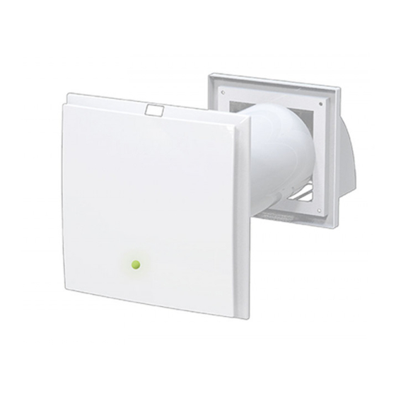
- Page 6 OPERATION OF THE PICO HP2 The ventilation unit consists of a fixed-length circular air duct, a ventilation unit, and an outdoor grill. The two motors, two filters and the exchanger are located within the inner duct. The filters are designed to purify the intake air and prevent the entry of objects foreign to the exchanger and fans.
-
Page 7: Operating Mode
OPERATING MODE RECOVERY UNIT THE UNIT RUNS FOR 70 SECONDS IN EXTRACTION MODE AND FOR 70 SECONDS IN INTAKE MODE, WITH THREE-SPEED CONTROL 70 secs. EXTRACTION THE UNIT WORKS IN ONLY EXTRACTING THE AIR FROM THE INTERIORS, WITH THREE-SPEED CONTROL INTAKE THE UNIT WORKS ONLY IN INTAKE MODE BY EXTRACTING AIR TO THE... -
Page 8: Installation And Setup
INSTALLATION AND SETUP WARNING! THE VENTILATION UNIT MUST NOT BE INSTALLED WHERE THE AIR DUCT CAN BE BLOCKED BY SHUTTERS, BLINDS, ETC. TO PREVENT DUST DEPOSITING AND ACCUMULATING. ALSO CURTAINS MAY BLOCK THE NORMAL FLOW OF AIR IN THE ROOM, MAKING THE UNIT'S OPERATION INEFFECTIVE. 1. - Page 9 3. Insert the pipe into the wall. The air duct must protrude by the distance indicated below: 5 mm 4. Attach the mounting plate by following the diagram on page 12. Prepare the four mounting holes and secure the mounting plate onto the part with four 4x40 screws, and four raw-plugs 6x40 (included).
- Page 10 5. Insert the filter, the ceramic exchanger, and another filter in consecutive order, into the air-duct. 6. Fit the ventilation unit onto the mounting plate. 6. Fit the ventilation unit onto the mounting plate. INSTALLING THE INTAKE GRID 1. Mark the fixing holes for the external ventilation grid and drill them. For convenience, use the back of the grid.
- Page 11 2. Insert the 6x40 raw-plugs (included) into the holes. 3. Now remove the external grid to allow access to the fixing holes. Remove the upper part of the external ventilation grid. 4. Secure the back of the grid to the wall with the 4x40 screws included.
-
Page 12: Connecting To The Mains
CONNECTING TO THE MAINS DISCONNECT THE VENTILATION UNIT FROM THE POWER SUPPLY BEFORE ANY ELECTRICAL INSTALLATION OPERATION. CONNECT THE VENTILATION UNIT TO AN OUTLET PROPERLY INSTALLED WITH TERMINAL GROUND. DO NOT MAKE ANY CHANGE TO THE INTERNAL CONNECTIONS: IT WOULD CAUSE THE LOSS OF WARRANTY The ventilation unit is calibrated for connection to single-phase AC mains supply 230 V/50 Hz with a 12 VDC transformer (supplied). -
Page 13: Using Remote Control
USING REMOTE CONTROL The ventilation unit is controlled by a remote control. The remote control has the capacity for more commands. REMOTE CONTROL DEVICE Ventilation unit ON Change speed Ventilation unit OFF MODE Intake Recovery unit unit works in intake mode only, extracting air to the outside and sucking it inside, the appliance runs for 70 seconds in with 3-speed control. - Page 14 REMOTE CONTROL DEVICE DESCRIPTION OF REMOTE-CONTROL BUTTONS 1. Switching on 2. Switching off 3. Speed setting First speed. Second speed. Third speed. 4. Operating mode MODE MODE Allows you to select the following modes Recovery unit The unit runs for 70 seconds in extraction mode and for 70 seconds in intake mode, with 3-speed control.
- Page 15 Vers. 01 - 29/01/2016 USER MANUAL WALL-MOUNTED STATIC EXTRACTION UNIT WITH MECHANICAL CROSS- FLOW AND HEAT RECOVERY...
- Page 16 VENTILATION UNIT OVERALL EXTERNAL DIMENSIONS DIMENSIONS (MM) VENTILATION UNIT TECHNICAL SPECIFICATIONS SPEED MIN. 1 MED. 2 MAX. 3 SUPPLY VOLTAGE 12Vdc POWER (W) MAX. POWER CONSUMPTION (A) MAX. AIR CAPACITY (m³/h) RPM (min-1) 2754 3060 3400 SOUND PRESSURE AT 1m (dB(A)) ACOUSTIC PRESSURE AT 3 m (dB(A)) MAX.
- Page 17 PICO RECO 100 OPERATION The ventilation unit consists of a fixed-length circular air duct, a ventilation unit, and an outdoor grill. The two motors, two filters and the exchanger are located within the inner duct. The filters are designed to purify the intake air and prevent the entry of objects foreign to the exchanger and fans.
- Page 18 OPERATING MODE RECOVERY UNIT THE UNIT RECOVERS HEAT (BY SIMULTANEOUS EXTRACTION AND INTAKE) AND HAS 3-SPEED CONTROL EXTRACTION THE UNIT WORKS IN ONLY EXTRACTING THE AIR FROM THE INTERIORS, WITH THREE-SPEED CONTROL INTAKE THE UNIT WORKS ONLY IN INTAKE MODE BY EXTRACTING AIR TO THE OUTSIDE AND SUCKING IT INSIDE, WITH 3-SPEED CONTROL AUTO1...
- Page 19 3. Install the duct through the wall with an inclination of 1 ° to the outside environment. 4. Attach the mounting plate by following the diagram on page 12. Prepare the four mounting holes and secure the mounting plate onto the part with four 4x40 screws, and four raw-plugs 6x40 (included).
- Page 20 5. Insert the filter, the ceramic exchanger, and another filter in consecutive order, into the air-duct. 6. Fit the ventilation unit onto the mounting plate. 6. Fit the ventilation unit onto the mounting plate.
- Page 21 INSTALLING THE INTAKE GRID 1. Mark the fixing holes for the external ventilation grid and drill for 6x40 plug. For convenience, use the back of the grid. 2. Insert the 6x40 raw-plugs (included) into the holes. 3. Now remove the external grid to allow access to the fixing holes. Remove the upper part of the external ventilation grid.
- Page 22 CONNECTING TO THE MAINS DISCONNECT THE VENTILATION UNIT FROM THE POWER SUPPLY BEFORE ANY ELECTRICAL INSTALLATION OPERATION. CONNECT THE VENTILATION UNIT TO AN OUTLET PROPERLY INSTALLED WITH TERMINAL GROUND. DO NOT MAKE ANY CHANGE TO THE INTERNAL CONNECTIONS: IT WOULD CAUSE THE LOSS OF WARRANTY The ventilation unit is calibrated for connection to the single-phase AC mains supply 230 V / 50 Hz using 12 VDC transformer.
- Page 23 USING REMOTE CONTROL The ventilation unit is controlled by a remote control. The remote control has the capacity for more commands. REMOTE CONTROL DEVICE Ventilation unit ON Change speed Ventilation unit OFF MODE Intake Recovery unit unit works in intake mode only, extracting air to the outside and sucking it inside, the unit recovers heat (by simultaneous with 3-speed control.
- Page 24 REMOTE CONTROL DEVICE DESCRIPTION OF REMOTE-CONTROL BUTTONS 1. Switching on 2. Switching off 3. Speed settings First speed. Second speed. Third speed. 4. Operating mode MODE MODE Allows you to select the following modes Recovery unit The unit recovers heat (by simultaneous extraction and intake) and has 3-speed control Extraction The unit works in only extracting the air from the interiors, with three-speed adjustment ’...
-
Page 25: Maintenance
MAINTENANCE UNPLUG THE UNIT FROM THE MAINS BEFORE STARTING MAINTENANCE. Maintenance of the ventilation unit means regular cleaning of its surfaces from dust and clean, and the replacement of its filters. 1. Fan maintenance (once a year). Pull on the ventilation unit to remove. Clean the impeller blades. - Page 26 2. Regenerator and filter maintenance (every 1,500 hours). Remove the air-flow rectifier. Remove the filter in front of the regenerator. Pull the regenerator cord to remove the air duct from the regenerator. Be careful when removing the regenerator, to avoid damage.
-
Page 27: Transportation And Storage
TRANSPORTATION AND STORAGE The unit should be stored in its original packaging in a ventilated area at a temperature of +10°C to +40 ° C. The air must not contain any aggressive vapours or chemical mixtures that can corrode, or compromise the integrity of, the connections.
Need help?
Do you have a question about the PICO HP2 Series and is the answer not in the manual?
Questions and answers