Table of Contents
Advertisement
Available languages
Available languages
Quick Links
MANUALE D'USO / USER MANUAL
VENTILATORE IN LINEA DA CANALE CIRCOLARE
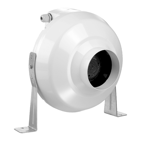
IN-LINE CIRCULAR DUCT FAN
• ACC500009 Ventilatore in linea da canale circolare Ø100
• ACC500010 Ventilatore in linea da canale circolare Ø125
• ACC500011 Ventilatore in linea da canale circolare Ø150/160
• ACC500012 Ventilatore in linea da canale circolare Ø200
• ACC500013 Ventilatore in linea da canale circolare Ø250
Tecnosystemi S.p.A. - Società Benefit
www.tecnosystemi.com
via dell'Industria, 2/4 - Z.I. San Giacomo di Veglia
31029 Vittorio Veneto (Treviso) - Italy
Phone +39 0438.500044 Fax +39 0438.501516
Numero Verde 800 904474
email: info@tecnosystemi.com
C.F. - P. IVA - R.I.TV IT02535780247 | Cap. Soc. € 5.000.000,00 i.v.
COD. CMU00125
REV. 01 / 14-07-2023
(only for Italy)
Advertisement
Chapters
Table of Contents

Subscribe to Our Youtube Channel
Related Manuals for Tecnosystemi ACC500009


Summary of Contents for Tecnosystemi ACC500009
- Page 1 REV. 01 / 14-07-2023 VENTILATORE IN LINEA DA CANALE CIRCOLARE IN-LINE CIRCULAR DUCT FAN • ACC500009 Ventilatore in linea da canale circolare Ø100 • ACC500010 Ventilatore in linea da canale circolare Ø125 • ACC500011 Ventilatore in linea da canale circolare Ø150/160 •...
-
Page 2: Table Of Contents
INDICE 1_AVVERTENZE GENERALI 2_DESCRIZIONE 2.1 Introduzione 2.2 Indicazioni generali 2.3 Scopo e contenuto delle istruzioni 2.4 Conservazione delle istruzioni 2.5 Aggiornamento delle istruzioni 2.6 Come utilizzare queste istruzioni 2.7 Rischi residui 2.8 Geralità sulla simbologia di sicurezza 2.9 Simboli di sicurezza utilizzati 2.10 Limiti di utilizzo e usi non consentiti 2.11 Identificazione dell’unità... -
Page 3: 1_Avvertenze Generali
1_AVVERTENZE GENERALI L’installazione e la messa in funzione devono essere conformi alle disposizioni del manuale e ai requisiti di tutte le normative elettriche, tecniche e di costruzione locali e nazionali vigenti. Tutte le operazioni connesse con il collegamento, regolazione, servizio e riparazione dell’articolo devono essere effettuati soltanto con la tensione della rete disinserita. Prima di installare la macchina, controllare l’integrità della ventola, del corpo, della griglia nonché l’assenza di oggetti estranei nella parte di passaggio che possano danneggiare le pale della ventola. Durante l’installazione del prodotto, evitare la compressione della cassa! La deformazione del corpo può comportare agli inceppamenti della girante e causare un maggior rumore. È vietato utilizzare l’articolo non conformemente alla destinazione e sottoporre il ventilatore al qualsiasi modifica o ultimazione. -
Page 4: 2_Descrizione
Le presenti istruzioni d’uso e installazione del prodotto, sono scaricabili e disponibili sul sito web www.tecnosystemi.com oppure possono essere richieste all’indirizzo mail assistenza@tecnosystemi. com, indicando modello e serial number del dispositivo. -
Page 5: Come Utilizzare Queste Istruzioni
La nostra azienda è a disposizione per fornire qualsiasi informazione riguardante l’utilizzo dei nostri prodotti. 2.6 COME UTILIZZARE QUESTE ISTRUZIONI Le istruzioni sono parte integrante della macchina. Prima di ogni operazione sulla macchina, gli utilizzatori o gli operatori sono tenuti a consultare le istruzioni e a farlo anche in caso di incertezza riguardante il trasporto, la movimentazione, l’installazione, la manutenzione, l’utilizzo e lo smantellamento della macchina. Per garantire la massima sicurezza durante le operazioni, le presenti istruzioni contengono simboli grafici che richiamano l’attenzione degli operatori e degli utilizzatori su specifiche procedure da eseguire in modo sicuro, come descritto nei paragrafi successivi. - Page 6 • Fare attenzione nel sollevamento dell’unità il cui baricentro può anche essere fortemente sbilanciato; • Fare attenzione nel bloccaggio delle funi/ganci di sollevamento; • Fare attenzione agli spigoli di lamiera all’interno dell’unità; • Fare attenzione agli spigoli di lamiera all’esterno dell’unità; • Fare attenzione alle possibili scottature derivanti da batterie di riscaldamento; La macchina è stata progettata in modo da ridurre al minimo i rischi per la sicurezza delle persone che con essa andranno ad interagire. In sede di progetto non è stato tecnicamente possibile eliminare completamente le cause di rischio. Pertanto è assolutamente necessario fare riferimento alle prescrizioni e alla simbologia di seguito riportata. COMPONENTI PREVENZIONE CONSIDERATI RISCHIO RESIDUO METODO DI LESIONE E PROTEZIONE (se presenti) Inserimento di oggetti Non infilare oggetti di Ventilatori Lesioni mentre i ventilatori stanno alcun tipo dentro le sezioni funzionando ventilanti Incendio a causa di corto...
-
Page 7: Geralità Sulla Simbologia Di Sicurezza
2.8 GENERALITÀ SULLA SIMBOLOGIA DI SICUREZZA Simboli di sicurezza singoli in conformità alla norma ISO 3864-2: DIVIETO Un simbolo nero inserito in un cerchio rosso con diagonale rossa indica un’azione che non deve essere eseguita. AVVERTENZA Un simbolo grafico nero inserito in un triangolo giallo con bordi neri indica un pericolo. AZIONE OBBLIGATORIA Un simbolo bianco inserito in un cerchio blu indica un’azione che deve essere fatta per evitare un rischio. 2.9 SIMBOLI DI SICUREZZA UTILIZZATI LEGGERE E COMPRENDERE LE ISTRUZIONI DELLA MACCHINA PRIMA DU EFFETTUARE QUALSIASI OPERAZIONE PERICOLO GENERICO Osservare scrupolosamente tutte le indicazioni poste a fianco del pittogramma. La mancata osservanza delle indicazioni può generare situazioni di rischio con possibili conseguenti danni alla salute dell’operatore e dell’utilizzatore in genere. PERICOLO ELETTRICO Osservare scrupolosamente tutte le indicazioni poste a fianco del pittogramma. -
Page 8: Limiti Di Utilizzo E Usi Non Consentiti
Per le informazioni elettriche non presenti nell’etichetta fare riferimento allo schema elettrico. Verificare che le caratteristiche della rete elettrica siano conformi ai dati riportati sulla targhetta di identificazione. Un FAC-SIMILE della targhetta è visualizzata qui sotto con la relativa legenda dei dati in essa riportati: Via dell'Industria, 2/4, 31029 - Vittorio Veneto TV. ITALY - info@tecnosystemi.com ACD500009 IN-LINE DUCT FAN Ø100 Supply: 230V - 50Hz Power: 80 W Working Temperature: 0T50°C "T"... -
Page 9: 3_Caratteristiche Tecniche
2. Motore 3. Girante 4. Staffa 5. Morsettiera Il ventilatore è dotato di un motore monofase con un rotore esterno, dotato di una girante centrifuga; Il ventilatore è progettato per il funzionamento continuo. 3.1 DATI ELETTRICI E PRESTAZIONALI ACC500009 ACC500010 ACC500011 ACC500012 ACC500013 Potenza elettrica assorbita (W) Corrente (A) 0.34 0.34 0.35 0.47 0.76... -
Page 10: Ecodesign
3.2 ECODESIGN & ENERGY LABELLING In accordo a Regolamento (UE) 1253/2014 e Regolamento (UE) 1254/2014 MARCHIO TECNOSYSTEMI MODELLO ACC500009 ACC500010 ACC500011 ACC500012 ACC500013 -52.8 -53.2 -53.7 -53.9 -53.7 Clima freddo Consumo specifico di -25.7 -26.1 -26.6 -26.8 -26.7 energia (SEC, kWh/ Clima temperato m2/a) e Classe SEC -10.2 -10.6 -11.1 -11.3 -11.2 Clima caldo Tipologia UVU, UVR – Unità di Ventilazione Unidirezionale, Residenziale Tipo di azionamento A velocità... -
Page 11: Curve Caratteristiche
3.3 CURVE CARATTERISTICHE ACC500009 ACC500010 ACC500011 ACC500012... - Page 12 ACC500013...
-
Page 13: 4_Installazione
4_INSTALLAZIONE AVVERTENZE GENERALI ED USO DEI SIMBOLI Tutte le operazioni effettuate sulla macchina devono essere eseguite da personale abilitato in ottemperanza alla legislazione nazionale vigente nel paese di destinazione. L’installazione e la manutenzione della macchina devono essere eseguite secondo le norme nazionali o locali in vigore. -
Page 14: Ricevimento Ed Ispezione
4.1 RICEVIMENTO ED ISPEZIONE All’atto dell’installazione o quando si debba intervenire sull’unità, è necessario attenersi scrupolosamente alle norme riportate su questo manuale, osservare le indicazioni a bordo unità e comunque applicare tutte le precauzioni del caso. La mancata osservanza delle norme riportate può causare situazioni pericolose. All’atto del ricevimento dell’unità, verificarne l’integrità: la macchina ha lasciato la fabbrica in perfetto stato; eventuali danni dovranno essere immediatamente contestati al trasportatore ed annotati sul documento di trasporto prima di firmarlo. Il Cliente deve compilare un rapporto scritto in caso di danno rilevante. Prima di accettare la consegna controllare: •... -
Page 15: Collegamenti Elettrici
aspirazione bisogna montare un deflettore. Nel caso di installazione orizzontalmente sul lato del condotto di aspirazione è necessario installare un condotto d’aria almeno di 1 metro di lunghezza. SEQUENZA DI MONTAGGIO Sequenza di montaggio 1. Rimuovere i bulloni su entrambi i lati della cassa, installare le staffe di montaggio e stringere i bulloni, allineando i 1. Rimuovere i bulloni su entrambi i lati della cassa, installare le staffe di montaggio e stringere i bulloni, allineando i fori nelle staffe con fori nelle staffe con i fori nella cassa. - Page 16 I cavi di alimentazione devono essere protetti a monte contro gli effetti del cortocircuito e del sovraccarico da un dispositivo idoneo conforme alle norme e leggi vigenti. La sezione dei cavi deve essere adeguata alla taratura del sistema di protezione a monte e deve tenere conto di tutti i fattori che la possono influenzare (temperatura, tipo di isolante, lunghezza, ecc.) L’alimentazione elettrica deve rispettare i limiti citati: in caso contrario la garanzia viene a decadere immediatamente. Effettuare tutti i collegamenti a massa previsti dalla normativa e legislazione vigente. Prima di iniziare qualsiasi operazione assicurarsi che l’alimentazione elettrica sia disconnessa. VERIFICHE PRELIMINARI Prima di procedere all’avviamento della macchina è necessario effettuare controlli preliminari della parte elettrica ed idraulica.
- Page 17 ALLACCIAMENTO ELETTRICO ALLACCIAMENTO ELETTRICO PRIMA DI ESEGUIRE QUALSIASI OPERAZIONE SUL PRODOTTO, SCOLLEGARLO DALLA PRIMA DI ESEGUIRE QUALSIASI OPERAZIONE SUL PRODOTTO, SCOLLEGARLO DALLA Non modificare i collegamenti elettrici dell’unità, in caso contrario la garanzia viene a decadere RETE ELETTRICA. RETE ELETTRICA. immediatamente. L’ALLACCIAMENTO ELETTRICO DEVE ESSERE ESEGUITO DA UN ELETTRICISTA L’ALLACCIAMENTO ELETTRICO DEVE ESSERE ESEGUITO DA UN ELETTRICISTA QUALIFICATO.
-
Page 18: 5_Manutenzione
5_MANUTENZIONE LA MANUTENZIONE DEL VENTILATORE VIENE ESEGUITA SOLO DOPO AVERLO SCOLLEGATO DALLA RETE. MANUTENZIONE VERIFICARE CHE IL PRODOTTO È STATO DISINSERITO DALLA RETE ELETTRICA LA MANUTENZIONE DEL VENTILATORE VIENE ESEGUITA SOLO DOPO AVERLO PRIMA DI TOGLIERE LA PROTEZIONE. SCOLLEGATO DALLA RETE. Pulire le superfici del prodotto ogni 6 mesi. Per effettuare la pulizia bisogna svitare le viti e togliere il coperchio del VERIFICARE CHE IL PRODOTTO E' STATO DISINSERITO DALLA RETE ELETTRICA PRIMA DI TOGLIERE LA PROTEZIONE... -
Page 19: 6_Disassemblaggio E Smaltimento
6_DISASSEMBLAGGIO E SMALTIMENTO Tutte le operazioni di messa fuori servizio devono essere eseguite da personale abilitato in ottemperanza alla legislazione nazionale vigente nel paese di destinazione. La struttura ed i vari componenti, se inutilizzabili, vanno demoliti e suddivisi a seconda della loro natura. Tutti i materiali devono essere recuperati o smaltiti in conformità alle norme nazionali vigenti in materia. - Page 20 NOTE NOTES...
- Page 21 COD. CMU00125 USER MANUAL REV. 01 / 14-07-2023 IN-LINE CIRCULAR DUCT FAN • ACC500009 In-line circular duct fan Ø100 • ACC500010 In-line circular duct fan Ø125 • ACC500011 In-line circular duct fan Ø150/160 • ACC500012 In-line circular duct fan Ø200 •...
- Page 22 TABLE OF CONTENTS 1_GENERAL WARNINGS 2_DESCRIPTION 2.1 Introduction 2.2 General indications 2.3 Purpose and content of the instructions 2.4 Storage of the instructions 2.5 Updated instructions 2.6 How to use these instructions 2.7 Residual risks 2.8 General information on safety symbols 2.9 Safety simbols used 2.10 Limits of use and non-permitted uses 2.11 Identification of the unit 3_TECHNICAL CHARACTERISTICS 3.1 Electrical and performance data 3.2 Ecodesign 3.3 Flow rate and airflow graphs 4_INSTALLATION 4.1 Receip and inspection 4.2 Storage 4.3 Unpacking 4.4 Mechanical and aeraulic connections 4.5 Electrical connection...
-
Page 23: 1_General Warnings
1_GENERAL WARNINGS All user’s manual requirements as well as the provisions of all the applicable local and national construction, electrical, and technical norms and standards must be observed when installing and operating the unit. Disconnect the unit from the power supply prior to any connection, servicing, maintenance, and repair operations. Check the unit for any visible damage of the impeller, the casing, and the grille before starting installation. The casing internals must be free of any foreign objects that can damage the impeller blades. While mounting the unit, avoid compression of the casing! Deformation of the casing may result in motor jam and excessive noise. Misuse of the unit and any unauthorised modifications are not allowed. Do not expose the unit to adverse atmospheric agents (rain, sun, etc.). Transported air must not contain any dust or other solid impurities, sticky substances, or fibrous materials. Do not use the unit in a hazardous or explosive environment containing spirits, gasoline, insecticides, etc. Do not close or block the intake or extract vents in order to ensure the efficient air flow. Do not sit on the unit and do not put objects on it. The information in this user’s manual was correct at the time of the document’s preparation. The Company reserves the right to modify the technical characteristics, design, or configuration of its products at any time in order to incorporate the latest technological developments. Never touch the unit with wet or damp hands. -
Page 24: 2_Description
It should be noted that this documentation is provided for informational purposes only and does not constitute a binding contract for third parties. The company undertakes to continuously improve and develop its products and reserves the right to make changes to specifications, fittings and documentation at any time, without notice and without the obligation to update the versions already delivered. These instructions for use and installation of the product can be downloaded from and are available on the website www.tecnosystemi.com or can be requested at the e-mail address assistenza@tecnosystemi.com, indicating the model and serial number of the device. 2.3 PURPOSE AND CONTENT OF THE INSTRUCTIONS These instructions provide essential information for installing, using, testing and maintaining the machine. They have been drawn up in compliance with the European Union regulations and with the technical standards in force at the time of their publication. Please observe the local safety regulations during installation. These instructions include indications to prevent improper use of the machine in a reasonably foreseeable manner. -
Page 25: How To Use These Instructions
2.6 HOW TO USE THESE INSTRUCTIONS The instructions are an integral part of the machine. Before any operation on the machine, users or operators are required to consult the instructions and to do so also in the event of uncertainty regarding transportation, handling, installation, maintenance, use and dismantling of the machine. To guarantee maximum safety during operations, these instructions contain graphic symbols which draw the attention of operators and users to specific procedures to be performed in a safe manner, as described in the following paragraphs. 2.7 RESIDUAL RISKS Residual risk identifies all the dangers that cannot be fully reduced through design and protection techniques, or potential danger that is not evident. This manual indicates every operation that can generate a risk situation in addition to the precautionary measures to be observed on a case-by-case basis •... - Page 26 • Be careful when lifting the unit whose centre of gravity may also be very unbalanced; • Be careful when locking the lifting ropes/hooks; • Pay attention to the sheet metal edges inside the unit; • Pay attention to the sheet metal edges on the outside of the unit; • Pay attention to possible burns deriving from heating coils; The machine has been designed in such a way as to minimise risks to the safety of persons who will be interacting with it. During the project it was not technically possible to completely eliminate the causes of risk. Therefore it is absolutely necessary to refer to the following instructions and symbols. COMPONENTS PREVENTION CONSIDERED RESIDUAL RISK INJURY METHOD AND PROTECTION (if present) Insertion of objects Do not insert objects of Fans Injuries while the fans are any kind into the ventilating in operation sections Fire due to short circuit Section of the cables or overheating and protection system...
-
Page 27: General Information On Safety Symbols
2.8 GENERAL INFORMATION ON SAFETY SYMBOLS Individual safety symbols according to the ISO 3864-2 standard: PROHIBITION A black symbol inserted in a red circle with a red diagonal indicates an action that must not be performed. WARNING A black graphic symbol inserted in a yellow triangle with black borders indicates a danger. COMPULSORY ACTION A white symbol inserted in a blue circle indicates an action that must be performed to avoid a risk. 2.9 SAFETY SYMBOLS USED READ AND UNDERSTAND THE MACHINE INSTRUCTIONS BEFORE CARRYING OUT ANY OPERATION GENERAL DANGER Strictly observe all the indications next to the pictogram. -
Page 28: Limits Of Use And Non-Permitted Uses
THIS UNIT IS NOT SUITABLE FOR OPERATION IN EXPLOSIVE ATMOSPHERES. 2.11 IDENTIFICATION OF THE UNIT Each unit is equipped with a plate fixed to the outside of the same, which shows the identification data of the machine and the main technical characteristics. For electrical information not present on the label, refer to the wiring diagram. Check that the characteristics of the electrical network comply with the data shown on the identification plate. A FAC- SIMILE of the plate is shown below with the relative legend of the data reported on it: Via dell'Industria, 2/4, 31029 - Vittorio Veneto TV. ITALY - info@tecnosystemi.com ACD500009 IN-LINE DUCT FAN Ø100 Supply: 230V - 50Hz Power: 80 W Working Temperature: 0T50°C "T" IPX4... -
Page 29: 3_Technical Characteristics
DESIGN AND OPERATING PRINCIPLE 1. Casing 2. Motor 3. Impeller 4. Mounting bracket 5. Terminal box The fan is equipped with a single-phase motor with an external rotor, equipped with a centrifugal impeller. The fan is rated for continuous operation. 3.1 ELECTRICAL AND PERFORMANCE DATA ACC500009 ACC500010 ACC500011 ACC500012 ACC500013 Power input (W) Current (A) 0.34 0.34 0.35 0.47 0.76 Maximum airflow (m3/h) 1080 2820... -
Page 30: Ecodesign
3.2 ECODESIGN & ENERGY LABELLING According to Regulation (EU) 1253/2014 and Regulation (EU) 1254/2014 TRADEMARK TECNOSYSTEMI MODEL ACC500009 ACC500010 ACC500011 ACC500012 ACC500013 -52.8 -53.2 -53.7 -53.9 -53.7 Cold Specific energy consumption (SEC, -25.7 -26.1 -26.6 -26.8 -26.7 Average kWh/m2/a) e Classe -10.2 -10.6 -11.1 -11.3 -11.2 Warm Type of ventilation unit UVU, RVU – Residential, unidirectional ventilation unit Type of drive installed Variable speed... -
Page 31: Flow Rate And Airflow Graphs
3.3 FLOW RATE AND AIRFLOW GRAPHS ACC500009 ACC500010 ACC500011 ACC500012... - Page 32 ACC500013...
-
Page 33: 4_Installation
4_INSTALLATION GENERAL WARNINGS AND USE OF SYMBOLS All operations performed on the machine must be carried out by qualified personnel in compliance with the national legislation in force in the destination country. The installation and maintenance of the machine must be performed according to the national or local regulations in force. Do not approach or insert any object into moving parts. HEALTH & SAFETY OF WORKERS The operator's workplace must be kept clean, tidy and free from objects that could restrict free movement. The workplace must be adequately lit for the intended operations. Insufficient or excessive lighting can cause risks. Ensure that excellent ventilation of the work rooms is always guaranteed and that the extraction systems are always functional, in an excellent condition and in compliance with the provisions of the law. PERSONAL PROTECTIVE EQUIPMENT The operators who carry out the installation and maintenance of the machine must wear the personal protection equipment required by law listed below. Protective footwear. -
Page 34: Receip And Inspection
4.1 RECEIPT AND INSPECTION When installing or servicing the unit, the rules indicated in this manual must be complied with, together with those on board the unit and, in any case, all necessary precautions must be taken. Failure to comply with these regulations may cause dangerous situations. On receiving the unit, check for any damage: the machine left the factory in perfect conditions; immediately report any signs of damage to the carrier and note them on the transport document before signing it. -
Page 35: Electrical Connection
aspirazione bisogna montare un deflettore. Nel caso di installazione orizzontalmente sul lato del condotto di aspirazione è necessario installare un condotto d’aria almeno di 1 metro di lunghezza. MOUNTING SEQUENCE: Sequenza di montaggio 1. Remove the bolts on both sides of the casing, install the mounting brackets and tighten the bolts, aligning the holes 1. Rimuovere i bulloni su entrambi i lati della cassa, installare le staffe di montaggio e stringere i bulloni, allineando i fori nelle staffe con in the brackets with the holes in the casing. - Page 36 The section of the cables must be suitable for the calibration of the protection system upstream and must take into account all the factors that could influence it (temperature, type of insulation, length, etc.) The power supply must comply with the stated limits: otherwise the warranty will be immediately voided. Performed all the ground connections required by the regulations and legislation in force. Before starting any operation make sure that the power supply is disconnected. PRELIMINARY CHECKS Before starting up the machine, it is necessary to carry out preliminary checks on the electrical and hydraulic parts. Commissioning operations must be performed in compliance with all the provisions of the preceding paragraphs. Malfunctions or damage may also result from the lack of proper care during shipping and installation. It is good practice to check before installation or commissioning that there is no damage due to tampering, vibrations during transportation or mistreatment suffered on site. • Check that the machine is installed to a professional standard and in compliance with the indications of this manual. • Check the electrical connection and the correct fastening of all the terminals. • Check that the voltage is the one shown on the unit data plate. •...
- Page 37 PRIMA DI ESEGUIRE QUALSIASI OPERAZIONE SUL PRODOTTO, SCOLLEGARLO DALLA PRIMA DI ESEGUIRE QUALSIASI OPERAZIONE SUL PRODOTTO, SCOLLEGARLO DALLA RETE ELETTRICA. RETE ELETTRICA. L’ALLACCIAMENTO ELETTRICO DEVE ESSERE ESEGUITO DA UN ELETTRICISTA L’ALLACCIAMENTO ELETTRICO DEVE ESSERE ESEGUITO DA UN ELETTRICISTA QUALIFICATO. QUALIFICATO. I VALORI NOMINALI DEI PARAMETRI ELETTRICI DEL PRODOTTO SONO INDICATI I VALORI NOMINALI DEI PARAMETRI ELETTRICI DEL PRODOTTO SONO INDICATI SULL’ETICHETTA DEL PRODUTTORE...
-
Page 38: 5_Technical Maintenance
5_TECHNICAL MAINTENANCE DISCONNECT THE UNIT FROM POWER SUPPLY BEFORE ANY MAINTENANCE OPERATIONS! MANUTENZIONE MAKE SURE THE UNIT IS DISCONNECTED FROM POWER MAINS BEFORE REMOVING THE PROTECTION LA MANUTENZIONE DEL VENTILATORE VIENE ESEGUITA SOLO DOPO AVERLO SCOLLEGATO DALLA RETE. Clean the product surfaces regularly (once in 6 months) from dust and dirt. To clean the fan, remove the self-tapping VERIFICARE CHE IL PRODOTTO E' STATO DISINSERITO DALLA RETE ELETTRICA PRIMA DI TOGLIERE LA PROTEZIONE screws and remove the fan cover. To clean the fan, use a soft cloth or a brush wetted in a mild detergent solution. -
Page 39: 6_Disassembly And Disposal
6_DISASSEMBLY AND DISPOSAL All the decommissioning operations must be performed by qualified personnel in compliance with the national legislation in force in the destination country. The structure and the various components, if unusable, must be demolished and divided according to their nature. All the materials must be recovered or disposed of in compliance with the relevant national regulations. 7_WEEE Do not disassemble or dispose of the product yourself. Disassembly, demolition and disposal of the product are extraordinary maintenance operations and must therefore be performed by qualified personnel. Pursuant to the local legislation and Directive 2012/19/EU on Waste Electrical and Electronic Equipment (WEEE)". The crossed-out wheeled bin symbol shown on the appliance or on the packaging indicates that the product at the end of its useful life must be collected separately from other waste to allow adequate treatment and recycling. Adequate differentiated collection for subsequent sending of the decommissioned equipment to environmentally compatible recycling, treatment and disposal helps to avoid possible negative effects on the environment and on health and promotes the re-use and/or recycling of the... - Page 40 Tecnosystemi S.p.A. Società Benefit www.tecnosystemi.com via dell’Industria, 2/4 - Z.I. San Giacomo di Veglia 31029 Vittorio Veneto (Treviso) - Italia Tel +39 0438.500044 - Fax +39 0438.501516 email: info@tecnosystemi.com 800 904474 ONLY FOR ITALY C.F. - P. IVA - R.I.TV IT02535780247 Cap.
Need help?
Do you have a question about the ACC500009 and is the answer not in the manual?
Questions and answers