
Related Manuals for DEMAG DIC 002 Series


Summary of Contents for DEMAG DIC 002 Series
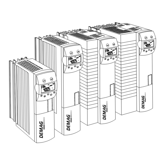
- Page 1 Quick-step operating instructions Dedrive Compact STO frequency inverters DIC-x-002 to DIC-x-210 Valid for software version 5.4.2/050-10 and higher with DIC-x-xxx-X-0000-x3 hardware 290623 en GB 211 170 44 720 IS 922...
- Page 2 Original operating instructions Manufacturer Demag Cranes & Components GmbH Forststrasse 16 40597 Düsseldorf, Germany www.demagcranes.com Email: info@demagcranes.com Part no. General accompanying documents Dedrive Compact STO frequency inverter quick-step operating instructions 211 170 44 Dedrive Compact STO frequency inverter application notes/operating instructions...
-
Page 3: Table Of Contents
Table of contents General ..................................6 Dedrive Compact STO frequency inverter ........................6 Symbols/signal words..............................6 Information on the operating instructions ........................6 Liability and warranty..............................7 Copyright ..................................7 Use of spare parts ............................... 7 Definition of personnel..............................7 After-sales service ............................... - Page 4 6.4.2.1 DIC-x-xxx-E ................................30 6.4.2.2 DIC-4-xxx-C................................31 6.4.3 DIC-2-018 and DIC-4-014 to 040 frequency inverters....................32 6.4.3.1 DIC-x-xxx-E ................................32 6.4.3.2 DIC-4-xxx-C................................33 6.4.4 DIC-4-045 to 120 frequency inverters ........................34 6.4.5 DIC-4-150 to 210 frequency inverters ........................36 Electric cabling and wiring ............................37 6.5.1 Safety instructions for electric cabling and wiring......................
- Page 5 8.5.1 General information on digital inputs and outputs ..................... 66 8.5.2 Function assignment of the digital inputs ........................66 8.5.3 Function assignment of the relay and digital outputs ....................67 Setpoint value generation in steps (SOST) ....................... 68 Stepless setpoint value generation with memory function (SOSP) ................69 Rotary encoder................................
-
Page 6: General
General Dedrive Compact STO frequency inverter You have purchased a Demag quality product. This frequency inverter is built in accordance with European standards and regulations and state-of-the-art engi‐ neering principles. Symbols/signal words Important safety information and instructions are marked by corresponding symbols and signal words in these in‐... -
Page 7: Liability And Warranty
Liability and warranty All information included in these instructions has been compiled on the basis of the relevant regulations, state-of- the-art engineering principles and our many years of experience. These instructions must be read carefully before starting any work on and with the frequency inverter, especially before it is put into service for the first time. -
Page 8: After-Sales Service
Trained person Trained persons are defined as persons who have been instructed and trained for the tasks assigned to them and on the possible hazards resulting from inappropriate conduct. Personnel must be informed about the required pro‐ tective devices, protective measures, relevant regulations, codes of practice, accident prevention regulations and operating conditions and must provide verification of their competence. -
Page 9: Safety
Knowledge of the contents of the operating instructions is one of the requirements necessary to protect personnel from hazards and to avoid malfunctions and, therefore, to operate the frequency inverter safely and reliably. Any conversions, modifications or additions to the machine are prohibited unless approved by Demag Cranes & Components GmbH in writing. -
Page 10: Hazards That Can Be Caused By The Frequency Inverter
CAUTION Prohibited activities Damage to / malfunction of the frequency inverter Under certain conditions, operation of frequency inverters is prohibited as this can result in malfunctions, equip‐ ment failure or danger to life and limb, e.g. in the case of: –... - Page 11 The STO "safe torque off" safety function according to DIN EN 61800-5-2 protects people from personal injury and the installation and operation from mechanical damage if the system is correctly specified. This function does not disconnect the installation from the power supply. The STO "safe torque off"...
-
Page 12: Notice On The Registration, Evaluation, Authorization And Restriction Of Chemicals (Reach)
● The Demag “Demag SCU” safety control unit can be used with suitable sensors and actuators to implement further safety-related functions. -
Page 13: Operating Personnel Requirements
The owner is obliged to ensure that ● the rules and regulations of the German Social Accident Insurance (DGUV) are applied in the Federal Repub‐ lic of Germany. ● national occupational safety and health regulations are observed and followed. Extract from the transfer list of the rules and regulations of German Social Accident Insurance (DGUV) Previous no. -
Page 14: Technical Data
DIC-4- for C: 004, 007, 014, 025 Voltage code 230 V 380 ... 480 V Compact STO Inverter Demag Designation Tab. 5 DIC-4-xxx-C frequency inverter Unlike model DIC-4-xxx-E frequency inverters, the following dimensions and R thermal resistance values th max apply for model DIC-4-xxx-C frequency inverters. -
Page 15: Selection Table
Selection table 3.5.1 DIC-2-003 to 018 frequency inverters The following data refer to the nominal working point of the frequency inverter. The nominal working point is de‐ fined for a permissible supply voltage of 230 V and a modulation frequency of 2 kHz. Size Current code DIC-2-…... -
Page 16: Dic-4-002 To 009 Frequency Inverters
3.5.2 DIC-4-002 to 009 frequency inverters The following data refer to the nominal working point of the frequency inverter. The nominal working point is de‐ fined for a permissible supply voltage of 400 V and a modulation frequency of 2 kHz. Size Current code DIC-4-…... -
Page 17: Dic -4-014 To 040 Frequency Inverters
3.5.3 DIC -4-014 to 040 frequency inverters The following data refer to the nominal working point of the frequency inverter. The nominal working point is de‐ fined for a permissible supply voltage of 400 V and a modulation frequency of 2 kHz. Size Current code DIC-4-…... -
Page 18: Dic-4-045 To 120 Frequency Inverters
3.5.4 DIC-4-045 to 120 frequency inverters The following data refer to the nominal working point of the frequency inverter. The nominal working point is de‐ fined for a permissible supply voltage of 400 V and a modulation frequency of 2 kHz. Size Current code DIC-4-…... -
Page 19: Dic-4-150 To 210 Frequency Inverters
3.5.5 DIC-4-150 to 210 frequency inverters The following data refer to the nominal working point of the frequency inverter. The nominal working point is de‐ fined for a permissible supply voltage of 400 V and a modulation frequency of 2 kHz. Size Current code DIC-4-…... -
Page 20: Operating Diagrams
Operating diagrams The technical data for the frequency inverter relates to the nominal working point that was selected for a wide range of applications. Functionally safe and economical dimensioning (derating) of the frequency inverter may be achieved by using the following diagrams for specific applications. Fig. -
Page 21: Scope Of Delivery, Transportation And Storage
Scope of delivery, transportation and storage Scope of delivery 4.1.1 General information on the scope of delivery Due to their modular hardware components, frequency inverters can be easily integrated into an automation con‐ cept. The scope of delivery described can be supplemented with optional components and adapted to customer- specific requirements. -
Page 22: Dic-2-018 And Dic-4-014 To 040 Frequency Inverters
4.1.3 DIC-2-018 and DIC-4-014 to 040 frequency inverters Fig. 6 Item Designation Make Type Frequency inverter Connection terminal X10 Phoenix ZEC 1,5 / 3 ST 5,0 Plug-in terminals for the relay output Standard fasteners for mounting on a wall panel Quick-step operating instructions, this document Control terminals X210A/X210B Wieland... -
Page 23: Dic-4-045 To 120 Frequency Inverters
4.1.4 DIC-4-045 to 120 frequency inverters Fig. 7 Item Designation Make Type Frequency inverter Connection terminal X10 Phoenix ZEC 1,5 / 3 ST 5,0 Plug-in terminals for the relay output Standard fasteners for mounting on a wall panel Quick-step operating instructions, this document Control terminals X210A/X210B Wieland DST 85/RM 3,5... -
Page 24: Dic-4-150 To 210 Frequency Inverters
4.1.5 DIC-4-150 to 210 frequency inverters Fig. 8 Item Designation Make Type Frequency inverter Connection terminal X10 Phoenix ZEC 1,5 / 3 ST 5,0 Plug-in terminals for the relay output Mounting brackets are not required, as the standard mounting points are fitted on the back of the heat sink. -
Page 25: Transport, Packing And Storage
Transport, packing and storage Safety warnings WARNING Falling parts Risk of injury from falling parts during transport, loading and unloading operations. – Do not step under suspended loads. Keep a sufficient safety distance. – Cordon off a large area around the working zone. WARNING Damage caused in transit The frequency inverter can be damaged or destroyed by inappropriate transport. -
Page 26: Project Engineering
Project engineering General information on project engineering Please contact your local Demag Cranes & Components GmbH sales office for drive specification to meet your particular application requirements or if you have any questions regarding specification. A team of specialists will be pleased to help you. -
Page 27: Assembly/Installation
Assembly/installation Safety instructions for assembly/installation DANGER Live components Danger to life and limb. Work on electric equipment may only be carried out by qualified specialist personnel ( "Definition of person‐ nel", Page 7) in compliance with the safety regulations. – It must be possible to switch off the power supply by means of a device to disconnect the power supply (e.g. - Page 28 EM extension module installation instructions Remove the cover before installing the extension module in slot C. Only AC may be applied to semi-conductor relay EM-S1OUTD on terminal X412 of extension module EM – UNI-01. DC loads can result in dangerous malfunctions. Digital outputs EM-S1OUTD and EM-S2OUTD on terminal X410A of the EM –...
-
Page 29: Checking The Installation Location
Checking the installation location Pay attention to the following when checking the installation location of the frequency inverter: ● Frequency inverters supplied as chassis units are designed to be mounted vertically on a panel in a switch‐ gear cabinet and feature IP20 enclosure. Ventilation/cooling must be ensured. ●... -
Page 30: Dic-2-003 To 010 And Dic-4-002 To 009 Frequency Inverters
6.4.2 DIC-2-003 to 010 and DIC-4-002 to 009 frequency inverters 6.4.2.1 DIC-x-xxx-E x ≥ 100 mm x ≥ 100 mm Fig. 10 CAUTION Hot components due to insufficient cooling Risk of burns on contact and fire hazard The units must be fitted with sufficient clearance to allow cooling air to circulate without any hindrance. Ensure that air pollution from sources such as dust, greases, aggressive gases, etc., is avoided. -
Page 31: Dic-4-Xxx-C
6.4.2.2 DIC-4-xxx-C Fig. 11 CAUTION Hot components due to insufficient cooling Risk of burns on contact and fire hazard A separate heat sink is required for DIC-4-xxx-C model frequency inverters. The switchgear cabinet wall must be provided with an opening that is as large as the frequency inverter mounting panel. -
Page 32: Dic-2-018 And Dic-4-014 To 040 Frequency Inverters
6.4.3 DIC-2-018 and DIC-4-014 to 040 frequency inverters 6.4.3.1 DIC-x-xxx-E x ≥ 100 mm x ≥ 100 mm Fig. 12 CAUTION Hot components due to insufficient cooling Risk of burns on contact and fire hazard The units must be fitted with sufficient clearance to allow cooling air to circulate without any hindrance. Ensure that air pollution from sources such as dust, greases, aggressive gases, etc., is avoided. -
Page 33: Dic-4-Xxx-C
6.4.3.2 DIC-4-xxx-C Fig. 13 CAUTION Hot components due to insufficient cooling Risk of burns on contact and fire hazard A separate heat sink is required for DIC-4-xxx-C model frequency inverters. The switchgear cabinet wall must be provided with an opening that is as large as the frequency inverter mounting panel. -
Page 34: Dic-4-045 To 120 Frequency Inverters
6.4.4 DIC-4-045 to 120 frequency inverters Fig. 14 CAUTION Hot components due to insufficient cooling Risk of burns on contact and fire hazard The units must be fitted with sufficient clearance to allow cooling air to circulate without any hindrance. Ensure that air pollution from sources such as dust, greases, aggressive gases, etc., is avoided. - Page 35 Fig. 15 Size 5 retaining arrangement Size 6 retaining arrangement Tab. 28...
-
Page 36: Dic-4-150 To 210 Frequency Inverters
6.4.5 DIC-4-150 to 210 frequency inverters Fig. 16 CAUTION Hot components due to insufficient cooling Risk of burns on contact and fire hazard The units must be fitted with sufficient clearance to allow cooling air to circulate without any hindrance. Ensure that air pollution from sources such as dust, greases, aggressive gases, etc., is avoided. -
Page 37: Electric Cabling And Wiring
Electric cabling and wiring 6.5.1 Safety instructions for electric cabling and wiring Electric cabling and wiring work must be carried out by qualified personnel according to the general and regional safety and installation regulations. Electric installation work and commissioning must be carried out according to the documentation and device specifications to ensure safe operation of the frequency inverter. -
Page 38: Conditions For Connection
6.5.2 Conditions for connection ● The frequency inverter is suitable for connection to a public or industrial power supply network according to the technical data. If the transformer output of the power supply network ≤ 500 kVA, the optional line reactor is only required for the frequency inverters marked accordingly in the technical data. -
Page 39: Modified Connection Assignment For Dedrive Compact Sto Units Compared To Previous Equipment Without Sto
Connections Line connection (A): provided the maximum permissible voltage drop is considered, the power supply line can be of any length, but it must be laid separately from control, data and motor cables. We recommend screened cables be fitted between the line filter and the frequency in‐ verter if an external line filter is used. -
Page 40: Block Diagram
6.5.5 Block diagram Fig. 18 CAUTION An incorrect DC load may damage the component. For DC, the relay contact must not be subjected to inductive load. Operation of a 24 V DC coupling relay is not permitted. The coil of the attached AC contactor must be provided with an RC filter. Changeover contact: Response time approx. -
Page 41: External 24 V Power Supply
For further information, see "Control terminals", Page 48. 6.5.6 External 24 V power supply Bi-directional control terminals X210A.1/X210A.2 can be used as a voltage output or a voltage input. Connecting an external DC power supply of 24 V ±10% to terminals X210A.1/ X210A.2 makes it possible to program parame‐ ters, to maintain the input and output functions and to communicate with the unit, even if the line power supply is switched off. -
Page 42: Mains Connection
6.5.8 Mains connection 6.5.8.1 DIC-2-003 to 010 and DIC-4-002 to 009 frequency inverters Fig. 19 3ph/400 V AC mains connection DIC-2-003 to 005 and DIC-4-002 to 004 DIC-2-010 and DIC-4-006 to 009 Keyed plug-in terminal Phoenix ZEC 1,5 / … ST 7,5 (1a) Phoenix ZEC 1,5 / …... -
Page 43: Dic-4-045 To 060 Frequency Inverters
6.5.8.3 DIC-4-045 to 060 frequency inverters Fig. 21 3ph/400 V AC mains connection DIC-4-045 to 060 Connection terminals Phoenix MKDSP 25 / 6-15,00-F Rigid cable 0,5 … 35 mm ; AWG 20 … 2 Flexible cable 0,5 … 25 mm ;... -
Page 44: Dic-4-075 To 120 Frequency Inverters
6.5.8.4 DIC-4-075 to 120 frequency inverters Fig. 22 3ph/400 V AC mains connection DIC-4-075 to 120 Connection stud M8 x 25; cable cross-section up to 70 mm Tab. 35 6.5.8.5 DIC-4-150 to 210 frequency inverters Fig. 23 3ph/400 V AC mains connection DIC-4-150 to 210 Connection stud M8 x 20;... -
Page 45: Motor Connection
6.5.9 Motor connection 6.5.9.1 General information on motor connection and cable lengths The motor and the braking resistor (Rb) must be connected to terminal X2 of the frequency inverter via screened cables which must be connected to the PE potential on both ends with good conductivity. Control, power supply and motor cables must be laid separately. -
Page 46: Dic-2-018 And Dic-4-014 To 040 Frequency Inverters
6.5.9.3 DIC-2-018 and DIC-4-014 to 040 frequency inverters Fig. 25 Motor connection DIC-2-018 and DIC-4-014 to 017 DIC-4-025 to 040 Connection terminals WAGO series 745/6 mm /RM7,5 WAGO series 745/16 mm /RM10+15 Rigid cable 0,2 … 6 mm ; AWG 24 … 10 0,2 …... -
Page 47: Dic-4-075 To 120 Frequency Inverters
6.5.9.5 DIC-4-075 to 120 frequency inverters 10 Nm 89 lb-in Fig. 27 Motor connection DIC-4-075 to 120 Connection stud M8 x 25; cable cross-section up to 70 mm Tab. 41 6.5.9.6 DIC-4-150 to 210 frequency inverters Fig. 28 Motor connection DIC-4-150 to 210 Connection stud M8 x 20;... -
Page 48: Control Terminals
6.5.10 Control terminals Fig. 29 Control terminals DIC-x-002 to 210 Control terminals Wieland DST85 / RM3,5 Rigid cable 0,14 … 1,5 mm ; AWG 30 … 16 Flexible cable 0,14 … 1,5 mm ; AWG 30 … 16 With wire end ferrule without plastic sleeve 0,25 …... - Page 49 CAUTION Modified connection assignment Drive not functioning due to missing release Dedrive Compact STO DIC-x-xxx-X-0000-x3 inverters have a different assignment for the X210B.2 control termi‐ nal compared to the previous DIC-x-xxx-X-0000-x0 and DIC-x-xxx-X-0000-x1 models. The STO A and STO B signals must be connected in parallel for replacement units.
-
Page 50: High Voltage Test
CAUTION The component may be damaged by incorrect loading of the relay contact. For DC, the relay contact must not be subjected to inductive load. Operation of a 24 V DC coupling relay is not permitted. The coil of the attached AC contactor must be provided with an RC filter. Hardware modules Due to their modular hardware components, frequency inverters can be easily integrated into an automation con‐... -
Page 51: Putting The Equipment Into Service
Putting the equipment into service Safety instructions when putting the equipment into service DANGER Live components Danger to life and limb. Work on electric equipment may only be carried out by qualified specialist personnel ( "Definition of person‐ nel", Page 7) in compliance with the safety regulations. –... -
Page 52: General Information On Commissioning
General information on commissioning Drive control The inverter is controlled via terminal strips X210A and X210B. Implementation The inverter is supplied with its parameters set to default values. See "Parameters/functions", Page 64 for a description of the parameters and functions. Refer to "Dedrive Compact STO frequency inverter application notes/operating instructions"... -
Page 53: Programming Parameters With The Kp500 Keypad Unit
Programming parameters with the KP500 keypad unit 7.3.1 Key assignment and displays Fig. 32 Key assignment and displays Parameters can be set and displayed and the frequency inverter can be controlled by means of the optional KP500 keypad unit. The keypad unit is not absolutely essential for operation of the frequency inverter and can be plugged in during operation, as required. -
Page 54: Actual Value Menu (Val)
7.3.2 Actual value menu (VAL) 42395344_xml.eps Fig. 33 Actual value menu (VAL) In the VAL sub-menu, the keypad unit displays many actual values depending on the configuration selected and on the hardware modules that are installed. The quick-step operating instructions document a selection of param‐ eters and the basic functions of the software. -
Page 55: Parameter Menu (Para)
7.3.3 Parameter menu (PARA) 42395444_xml.eps Fig. 34 Parameter menu (PARA) The parameters that are polled during guided set-up have been selected from existing applications and should be supplemented by further settings in the PARA sub-menu, if required. The quick-step operating instructions de‐ scribe the basic parameters and the basic functions of the software. -
Page 56: Programming Parameters With Parcom Compact Software
Programming parameters with Parcom Compact software 7.4.1 General information on programming parameters with Parcom Compact software Please observe the safety instructions, "Hazards that can be caused by the frequency inverter", Page 10, "Safety instructions for assembly/installation", Page 27 and "Safety instructions when putting the equipment into service", Page 51. -
Page 57: Window Layout
7.4.3 Window layout Fig. 36 Item Designation Item Designation Item Designation Menu bar Directory window Status bar Toolbar Parameter window Tab. 53 Parcom Compact software with its graphical user interface facilitates simple programming of the inverter parame‐ ters. The mouse or the keyboard can be used. The width and height of the windows as well as the width of the columns in the parameter window can be changed by holding and dragging the separators. -
Page 58: Switching On The Power Supply
7.5.2 Switching on the power supply After the installation work has been completed, all control and power connections must be checked again before the power supply is switched on. If all the electric connections are correct, ensure that controller release of the frequency inverter is switched off (control input S1IND / STO A and S7IND / STO B open). - Page 59 The default rated values must be checked and, if necessary, changed by the user. Change the values with the ▲ ▼ keys and confirm entry with the key. Enter the lower of the two voltages for Demag ZBA motors with a wide voltage range, e.g. 380 - 400 V. Parameters Setting...
- Page 60 Warning messages Code Measures/remedy SA004 The Rated speed 372 and the Rated frequency 375 must be checked. The slip for an asynchronous motor is in the limit range. SA054 Resolver offset not set Tab. 55 Possible error messages during the plausibility check If an error message appears, check and enter the programmed rated data again.
- Page 61 Unintended movement of the drive Danger to life and limb. Parameter identification releases the brake of conical-rotor motors (Demag KB motors) without any drive torque being developed. For this reason, the drive must be secured against any unintended movement. The "Release brake" function of the digital outputs is not activated during the parameter identification process.
- Page 62 Error messages Code Measures/remedy SF011 Measurement of main inductance has failed because the motor has a high slip. Correct the rated motor values in parameters 370, 371, 372, 374, 375, 376 and 812. Repeat parameter identification. SF012 Measurement of leakage inductance has failed because the motor has high slip. Correct the rated motor values in parameters 370, 371, 372, 374, 375, 376 and 812.
- Page 63 The keypad unit display the End message, which you should confirm with the key. Guided set-up of the frequency inverter is completed with a reset and initialisation of the frequency inverter. The Dedrive Compact STO reports a fault during initialisation. Fig.
-
Page 64: Parameters/Functions
Parameters/functions General information on parameters/functions The following tables contain basic values for the parameters that are also set when the unit is supplied. A PC with Parcom Compact parameter programming software which is connected to one of the optional RS 232 modules 537 769 84 or 537 723 84 via data cable 537 237 84 can be used to configure and program the inverter parameters. - Page 65 Case 2: Brake application time is longer than the remaining deceleration time Fig. 44 Case 2: Brake application time is longer than the remaining deceleration time Output frequency "Modulation on" message Brake application time SW-Step 1+ input Calculated cut-off value DC post-magnetisation time "Release brake"...
-
Page 66: Error Acknowledgement
Parameters Setting Explanation Name Unit Min. Max. Default Operational Behaviour ➜ Brake-Control Brake application time [ms] 2000 Tab. 66 Error acknowledgement After it has been successfully acknowledged, the "Error" message is cancelled and the "Ready" message is out‐ put. If the cause of the error has not been eliminated, the error cannot be acknowledged. All error information is saved in the error memory (see ... -
Page 67: Function Assignment Of The Relay And Digital Outputs
Parameters Setting Explanation Name Unit Min. Max. Default Control Inputs/Outputs ➜ Digital Inputs SW-Step 1+ 71 - S2IND SW-Step 1 - 72 - S3IND (SOST) Step 2 75 - S6IND (SOSP) Acceleration 75 - S6IND Tab. 68 8.5.3 Function assignment of the relay and digital outputs Available: ●... -
Page 68: Setpoint Value Generation In Steps (Sost)
Setpoint value generation in steps (SOST) Operating principle, general information All reference value step functions are activated when current flows through the relevant input. The input signals are filtered by the hardware and software. An edge from "Off" to "On" must be created following the ready for operation signal in order to obtain a valid set‐ point value. -
Page 69: Stepless Setpoint Value Generation With Memory Function (Sosp)
Diagram showing 2-stage reference value steps Fig. 46 (SOST) Step 2 input SOST step 2 481 frequency value SW-Step 1+ input SOST step 1 480 frequency value Tab. 71 Stepless setpoint value generation with memory function (SOSP) Operating principle, general information All setpoint value memory functions are activated when current flows through the relevant input. - Page 70 SOSP input assignment (default) The following table shows the assignment of the digital inputs when the unit is delivered. The assignments can be freely re-programmed. Parameters Setting Explanation Name Unit Min. Max. Default Control Inputs/Outputs ➜ Digital Inputs SW-Step 1+ 71 - S2IND SW-Step 1 - 72 - S3IND...
-
Page 71: Rotary Encoder
Rotary encoder 8.8.1 General information on the rotary encoder The actual speed value needs to be measured continuously for the control and regulation process for some of the available settings in Configuration 30. The required incremental rotary encoder must be connected to digital control terminals S5IND (channel A) and S4IND (channel B) of the frequency inverter. -
Page 72: Encoder Filter Time Constant
Min. number of Division Marks S 60 s/min = Min. speed of the motor in rpm = 500 Hz ∙ A = Evaluation (1, 2, 4) A ∙ n Tab. 76 To ensure good drive running characteristics, an encoder signal must be evaluated at least every 2 ms (signal frequency f = 500 Hz). -
Page 73: Diagnosis
- No power supply - If the supply voltage is applied to L1, L2, L3, a serious device error has occurred. Please contact Demag Cranes & Components GmbH after-sales service. Brief initialisation and Self-Test after the power supply is switched on. -
Page 74: Warning Message
Warning message The key to be read out via the Warnings 269 parameter may consist of several messages. Key A0088 indicates individual warning messages A0008 + A0080, for example. For SAxxx and SFxxx messages, see "Setup", Page 58. Warning Status coding AXXXX ABCDE Warning key... - Page 75 & wiring and EMC. STO safety F1204 The software self-test has detected an internal error. Contact Demag Cranes & Components GmbH after-sales service. function F1205 5-second monitoring error message The STO A and STO B switch-off paths were not connected simultaneously, but with an inter‐...
-
Page 76: Repairs
Repairs 10.1 General information on repairs Safety WARNING Observe the safety instructions in the relevant chapters. Maintenance The frequency inverter is largely maintenance-free. Ensure that air circulates freely, e.g.: ● regularly remove dust deposits; ● clean or replace blocked filters (such as filters fitted in the doors of switchgear cabinets). Storage The unit must not be stored for more than 1 year. -
Page 77: Parameters
Parameters 11.1 Extract from the list of parameters For further information, see "Dedrive Compact STO frequency inverter application notes/operating instructions" and extension module operating instructions. Parameters Setting Explanation Name Unit Min. Max. Default Inverter Data Inverter Software Version Control Level 410 - FOR without en‐... - Page 78 Parameters Setting Explanation Name Unit Min. Max. Default Motor Data ➜ Encoder 1 "Operation Mode Encoder Operation Mode Encoder 1 1 - single 4 - quadruple 0 - off 1", Page 71 "Division Marks Encoder 1", Division Marks Encoder 1 8192 1024 Page 71...
-
Page 79: Accessories
Accessories 12.1 Line reactors, line filters, output filters 12.1.1 General For further information, data and dimensions on line fuses and braking resistors, see "Frequency inverter acces‐ sories technical data" Tab. 1, Page 2. 12.1.2 DIC-2-003 to 018 Dedrive Compact STO DIC-2-… Line reactors until 08/2017 Part no. -
Page 80: Optional Modules/Options
12.2 Optional Modules/Options Dedrive Compact STO DIC-x-… Designation Part no. Remarks KP500 keypad unit 537 722 84 KP 232 interface converter 537 769 84 CM RS 232 communication module 537 723 84 1,8 m data cable 537 237 84 Parcom Compact parameter programming software ... -
Page 81: Block Wiring Diagram
Normally open: 240 V AC/5 A; 24 V DC/5 A (ohmic) Optional line filter Line connection Normally closed: 240 V AC/3 A; 24 V DC/1 A (ohm‐ Optional output filter Analogue setpoint value Response time: approx. 40 ms Brake control PWM-analogue inverter Brake (option) Demag DSE/DST PWM module Tab. 91... - Page 84 PO Box 67 · 58286 Wetter (Germany) Phone +49 (0)2335 92-0 +49 (0)2335 92-7676 www.demagcranes.com Reproduction in whole or in part only with prior consent of Demag Cranes & Components GmbH, 58286 Wetter (Germany) Subject to change. Not liable for errors or omissions.
Need help?
Do you have a question about the DIC 002 Series and is the answer not in the manual?
Questions and answers