
Related Manuals for DEMAG DRF 200


Summary of Contents for DEMAG DRF 200
- Page 1 Assembly instructions DRF 200 friction wheel travel drive with travel motor 120914 en GB 214 395 44 719 IS 913.92...
- Page 2 Please fill in the following table before first putting the unit into service. This provides you with definitive documentation of your Demag DRF 200 friction wheel travel drive and important information if you ever have to contact the manufacturer or his rep‐...
-
Page 3: Table Of Contents
General..................................8 Safety signs on the equipment ............................ 8 Intended use................................8 Hazards that can be caused by the DRF 200 friction wheel travel drive..............9 Responsibility of the owner ............................10 Operating personnel requirements..........................11 Personal protection equipment..........................11 Regular inspections.............................. - Page 4 Link bar..................................30 Load bar ..................................31 Connecting the electric equipment ..........................31 Putting into service for the first time .......................... 32 Safety instructions when putting into service for the first time................... 32 Inspection regulations ............................... 32 Checks on entering service, handover ........................33 Operation...................................
-
Page 5: General
These instructions must be read carefully before starting any work on and with the DRF 200 friction wheel travel drive, especially before it is put into service for the first time. The manufacturer assumes no liability for any dam‐... -
Page 6: Copyright
Copyright These instructions are only intended to be used by the people who work with or on the DRF 200 friction wheel travel drive. Any and all content, texts, drawings, images and any other information are protected within the sense of copyright law and are subject to further industrial rights. -
Page 7: After-Sales Service
Specifying this data ensures that you receive the correct information or the required spare parts. The current addresses of the sales offices in Germany and the subsidiaries and agencies worldwide can be found on the Demag Cranes & Components GmbH homepage at www.demagcranes.com/Contact... -
Page 8: Safety
In particular, the manufacturer assumes no liability for damage due to inappropriate or any other prohibited use of the DRF 200 friction wheel travel drive in the sense of the "In‐ tended use" section. -
Page 9: Hazards That Can Be Caused By The Drf 200 Friction Wheel Travel Drive
Depending on the type and scope of the DRF 200 friction wheel travel drive, it may be necessary to have an in‐ spection carried out by an expert engineer before it is handed over to the owner. -
Page 10: Responsibility Of The Owner
Responsibility of the owner Information on safety at work refers to the regulations of the European Union that apply when the DRF 200 friction wheel travel drive is manufactured. The owner is obliged to ensure that the specified industrial safety measures comply with the latest rules and regulations and to observe new regulations during the entire service life of the DRF 200 friction wheel travel drive. -
Page 11: Operating Personnel Requirements
Operating personnel requirements Only authorised and trained personnel may work on the installation. The personnel must have received instruction on the installation functions and any hazards that may occur. Every individual given the task of working on or with the installation must have read and understood the instruc‐ tions before any work starts. -
Page 12: Technical Data
KBK I, II-L, II, II-H link bar, short for straight travel KBK I, II-L, II, II-H link bar, long for travel on curved tracks Tractor trolley Tractor trolley Dished washer stack Dished washer stack DRF 200 DRF 200 Curve travel guide arm Tab. 3... -
Page 13: Travel Speed, Motor Size And Maximum Permissible Total Displaceable Load
Travel speed, motor size and maximum permissible total displaceable load 3.2.1 General ● Friction wheel travel drive without a motor weighs 12 - 14 kg. ● Motor duty factor 40% CDF or 40/20% CDF for pole-changing motors. ● Calculated with a travel resistance of 160 N/t. ●... -
Page 14: Motor Key Data
Motor key data 3.3.1 ZBF motor Size for 50 Hz, 3 ~ φN 230 V 400 V 500 V [kW] [rpm] ZBF 63 A 2 B004 0,26 2630 1,30 0,76 0,61 3,40 0,78 ZBF 63 A 4 B004 0,13 1370 0,75 0,43 0,34... -
Page 15: Dimensions
Fig. 3 Item Designation Item Designation DRF 200 with ZBF 63/71 motor Narrow version with ZBF 63/71 motor only for KBK III DRF 200 with ZBF 80 motor Narrow version with ZBF 80 motor only for KBK III Tab. 10... - Page 16 Trolley for DRF 200 Fig. 4 Item Designation Item Designation Trolley for straight travel as tractor trolley Trolley with curve travel guide arm as tractor trolley Tab. 11...
-
Page 17: Transport, Packing And Storage
Packing DRF 200 friction wheel travel drives, the accessories and the trolleys are shipped in cardboard packing. If no agreement has been made on the return of the packing material, separate the materials according to type and size and make them available for further use or recycling. -
Page 18: Technical Description
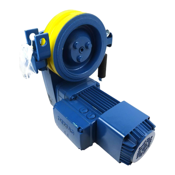
The friction wheel with HydroPUR tyre is driven via a gearbox and electric motor. The gearbox of the DRF 200 is a 3-stage spur wheel gearbox. The gearbox housing is designed in such a way that it can be fitted direct to the relevant trolleys. -
Page 19: Runway
When selecting a track, we recommend you specify the special profile sections (see "Trolley for KBK crane construction kit", Page 20) of our Demag KBK crane construction kit. They are characterised by their low deadweight. The cold-rolled track sections feature a smooth run‐... -
Page 20: Trolley For Kbk Crane Construction Kit
KBK rails. The wide friction wheel should be used for KBK II, and the narrow friction wheel for KBK III. DRF 200 mounting components can be relocated to vary the position of the spring assembly and motor as required. Contactor control and timed mechani‐... -
Page 21: Disengaging Device
Disengaging device The counterweight is used to manually relieve the pre-tension of the dished washer stack. The trolley and drive can be pushed along the track by hand when the tension on the dished washer stack is released. Fig. 8 Buffer fitting Fig. -
Page 22: Power Supply Lines
4.10 Power supply lines Fig. 10 Example of a current collector arrangement on a DRF 200 trolley Power supply is provided via a specially developed current collector system. The DEL current collector system is suitable for travel through horizontal and vertical curves in the specified per‐... -
Page 23: Assembly
The wiring of DRF 200 friction wheel travel drives complies in all respects with current DIN VDE and accident pre‐ vention regulations. -
Page 24: Tightening Torques
All assembly work must be completed in accordance with the assembly instructions. Operation with defective or damaged DRF 200 friction wheel travel drives results in a high risk of accidents with personal injuries and dam‐ age to the installation and is, therefore, strictly prohibited. -
Page 25: Installation Procedure
Check the delivery is complete "Transport, packing and storage", Page 17. Release air from the friction wheel travel drive "Preparing for installation", Page 25. Assemble the DRF 200 with trolley. Attach the hoist unit. Connect to the power supply "Connecting the electric equipment", Page 31. -
Page 26: Trolleys
Trolleys Trolley for straight travel Fig. 12 Item Designation Item Designation Load trolley, max. load capacity 270 kg Spacer sleeve for load trolley or tractor trolley Tractor trolley Spacer sleeve for tractor trolley Tab. 18... - Page 27 Max. flange thickness [mm] = flange width - 60 mm Max. web thickness [mm] ■■■■■■■■■■■■■■■■■■■■■■■■■■■■■■■■■■■■■■■■■■■■■■■■■■■■■■■■■■■■■■■■■■■■■■■■■■■■■■■■■■■■■■■■■■■■■■■■■■■■■■■■■■■■■■■■■■■■■■■■■■■■■■■■■■■■■■■■■■■■■ Flange width [mm] 82 - 130 Load bar [mm] Load trolley Item 1 4 x 26,9 x 2,65 x 25,5 Spacer sleeve Item 1 2 x 26,9 x 2,65 x 25,5 Tractor trolley Item 2 2 x 26,9 x 2,65 x 43...
- Page 28 Trolley with curve travel guide arm Fig. 13 Item Designation Item Designation Load trolley, max. load capacity 270 kg Spacer sleeve for load trolley or tractor trolley Tractor trolley Spacer sleeve for tractor trolley Tab. 20...
- Page 29 Max. flange thickness [mm] = flange width - 70 mm Max. web thickness [mm] ■■■■■■■■■■■■■■■■■■■■■■■■■■■■■■■■■■■■■■■■■■■■■■■■■■■■■■■■■■■■■■■■■■■■■■■■■■■■■■■■■■■■■■■■■■■■■■■■■■■■■■■■■■■■■■■■■■■■■■■■■■■■■■■■■■■■■■■■■■■■■ Flange width [mm] 100 - 130 Load bar [mm] Load trolley Item 1 4 x 26,9 x 2,65 x 25,5 Spacer sleeve Item 1 2 x 26,9 x 2,65 x 25,5 Tractor trolley Item 2 2 x 26,9 x 2,65 x 43...
-
Page 30: Link Bar
Trolley suspension Fig. 14 Flange thickness t [mm] Number of washers, item (1) Fig. 14, Page 30 Order no. 340 542 44 Bolt length, item (2) Fig. 14, Page 30 [mm] Order no. 300 250 44 300 251 44 300 252 44 300 253 44 Tab. -
Page 31: Load Bar
Load bar Ø20 Ø26 122,5 Fig. 16 WARNING Overload Danger to life and limb due to an overload. The maximum permissible safe working load is 270 kg for non-guided loads which are allowed to swing freely. Connecting the electric equipment Mains connection First check to ensure that the voltage and frequency specified on the rating plate match your mains supply. -
Page 32: Putting Into Service For The First Time
Putting into service for the first time Safety instructions when putting into service for the first time WARNING Safe operation of the installation is not yet ensured when it is first put into operation. The installation may only be put into operation if it has been installed/assembled according to the assembly in‐ structions. -
Page 33: Checks On Entering Service, Handover
Checks on entering service, handover WARNING Unauthorised operation Danger to life and limb if the installation is operated without previous inspection. The installation may only be put into service if it has been checked according to the accident prevention regula‐ tions. -
Page 34: Operation
The owner must arrange for operating personnel to be trained. WARNING Risk of burns Risk of burns from contact when the DRF 200 friction wheel travel drive is in operation. Do not touch hot motor housings. WARNING Non-compliance with operating regulations/industrial safety regulations Danger to life and limb if relevant regulations are disregarded. -
Page 35: Function Checks
Take the installation out of service immediately if functional defects or irregularities are detected. – The operator is obliged to check the DRF 200 friction wheel travel drive for any visible damage at least once per shift and to report any damage immediately. -
Page 36: Taking The Equipment Out Of Operation
Taking the equipment out of service when faults occur DRF 200 friction wheel travel drives must be switched off immediately in the event of the following faults: ● If electric devices and cables as well as parts of the insulation are damaged. -
Page 37: Maintenance/Repair
WARNING Risk of burns Risk of burns from contact after the DRF 200 friction wheel travel drive has been in operation. Do not touch hot motor housings. Allow the motor to cool down before performing any maintenance or repair work. -
Page 38: Basic Maintenance Requirements
Maintenance work which is not possible from the ground may only be carried out from work stands or platforms. The danger zone below the DRF 200 friction wheel travel drive must be fenced off if there is a risk of falling ob‐... -
Page 39: Maintenance Schedule
After finishing maintenance work Re-install safety devices as required by relevant regulations and check them for correct operation after finishing maintenance work. Maintenance schedule Activity Before first putting 3 months after ini‐ Before starting Every 6 months During the annual into operation tial commission‐... -
Page 40: Maintenance Work
Maintenance work 8.4.1 Oil lubrication General information on oil lubrication Under normal operating conditions, the lubricant must be changed after 10000 hours of service. The lubricant should, however, be changed at least every 4 years. Under exceptional operating conditions, e.g. high ambient temperatures, we recommend that the oil should be changed at shorter intervals. -
Page 41: Brake
8.4.3 Brake 8.4.3.1 General DANGER Inappropriate maintenance work Danger to life and limb. Risk of material damage. Check brake air gap s at certain intervals and adjust it, as required. If the brake is not adjusted, it will no longer release after further wear. If the motor then operates against the applied brake, the brake and motor may be damaged. -
Page 42: Checking And Adjusting Brake Air Gap S
8.4.3.2 Checking and adjusting brake air gap s Fig. 17 Item Designation Item Designation Item Designation Fan cover retaining bolts Armature plate Magnet assembly Fan cover Brake disc Feeler gauge Retaining ring Collared pin End cap Fan wheel Hexagon nuts Stop plate Tab. - Page 43 Remove fan cover (2) from the motor. Remove retaining ring (3) from the shaft. Remove fan wheel (4) from the shaft. Check the remaining thickness of brake disc (6), see Tab. 27, Page 41. If the edge of armature plate (5) has reached mark (x) on collared pin (7), brake disc (6) must be replaced, see ...
-
Page 44: Replacing The Brake Disc
8.4.3.3 Replacing the brake disc Fig. 18 Item Designation Item Designation Item Designation Terminal box cover Armature plate End cap Hexagon nuts Brake disc Brake springs Magnet assembly Distance springs Magnet assembly connecting cable Stop plate Collared pin Tab. 29... - Page 45 Proceed as follows to replace the brake, see also "Checking and adjusting brake air gap s ", Page 42: ● Unscrew the four retaining bolts of the fan cover. ● Remove the fan cover from the motor. ● Remove the retaining ring from the shaft. ●...
-
Page 46: Friction Wheel Drive
8.4.4 Friction wheel drive 8.4.4.1 Removing and installing the friction wheel Fig. 19 Item Designation Item Designation Item Designation Friction wheel Hexagon bolts Tab. 31 To replace friction wheel (1), unscrew the three hexagon bolts (2). The tightening torque of hub (3) must be checked and, if necessary, re-tightened before friction wheel (1) is installed. -
Page 47: Removing And Installing The Suspension Fork And Suspension
8.4.4.2 Removing and installing the suspension fork and suspension Fig. 20 Item Designation Item Designation Suspension fork Hexagon bolt suspension Hexagon bolt suspension fork Eye bolt Tab. 32 Install suspension fork (1) with hexagon bolt (2). Tighten hexagon bolt (2) to a tightening torque of 270 Nm. On both sides of the friction wheel, tighten hexagon bolts (3) for the suspension to a tightening torque of 70 Nm. -
Page 48: Malfunctions/Warnings
WARNING Risk of burns Risk of burns from contact after the DRF 200 friction wheel travel drive has been in operation. Do not touch hot motor housings. Allow the motor to cool down before eliminating the fault. Conduct when malfunctions occur Bring the installation to an immediate standstill by actuating the emergency stop without delay if malfunctions occur that result in an immediate danger of personal injury, damage and/or an operating hazard. -
Page 49: Disassembly/Disposal
Disassembly/disposal 10.1 General WARNING Before disassembly, follow the safety instructions in "Maintenance/repair", Page 37 of these operating in‐ structions. Unless a return or disposal agreement has been concluded, separated components must be recycled after proper removal: ● Scrap any remaining metallic material, ●... - Page 50 Authorised representative for technical documentation Hans-Jörg Böttcher, Demag Cranes & Components GmbH, Forststrasse 16, 40597 Düsseldorf, Germany Düsseldorf, 13.07.2018 ppa.
- Page 52 PO Box 67 · 58286 Wetter (Germany) Phone +49 (0)2335 92-0 +49 (0)2335 92-7676 www.demagcranes.com Reproduction in whole or in part only with prior consent of Demag Cranes & Components GmbH, 58286 Wetter (Germany) Subject to change. Not liable for errors or omissions.
Need help?
Do you have a question about the DRF 200 and is the answer not in the manual?
Questions and answers
What is the horsepower of DRF200?