
Related Manuals for DAKOTA ULTRASONICS CMX DL


Summary of Contents for DAKOTA ULTRASONICS CMX DL
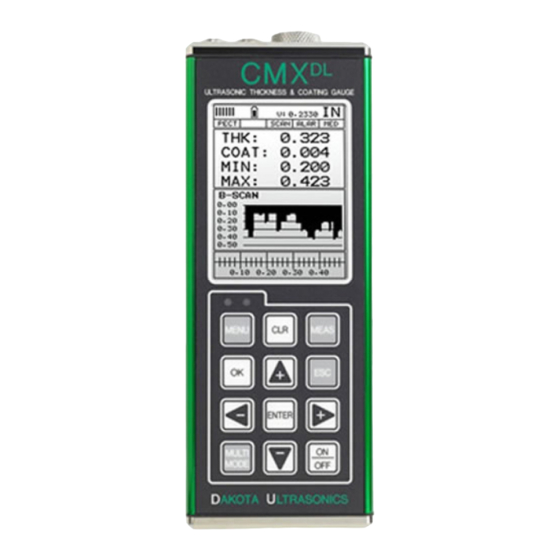
- Page 1 OPERATION MANUAL DAKOTA ULTRASONICS Material & Coating Thickness Gauge P/N P-171-0002 Rev 1.30, April 2008 1.800.544.2843 www.calcert.com sales@calcert.com...
-
Page 2: Table Of Contents
CHAPTER ONE INTRODUCTION ...............1 CHAPTER TWO QUICK STARTUP GUIDE ............2 CHAPTER THREE KEYBOARD, MENU, & CONNECTOR REFERENCE..22 CHAPTER FOUR PRINCIPALS OF ULTRASONIC MEASUREMENT .....31 CHAPTER FIVE SELECTING THE MEASUREMENT MODE ......36 CHAPTER SIX MAKING MEASUREMENTS .............39 CHAPTER SEVEN USING THE DIGITS & B-SCAN DISPLAYS ......55 CHAPTER EIGHT THRU PAINT MEASUREMENT TECHNIQUE ....66 CHAPTER NINE PULSE-ECHO COATING &... -
Page 3: Chapter One Introduction
Dakota Ultrasonics maintains a customer support resource in order to assist users with questions or difficulties not covered in this manual. Customer support may be reached at any of the following: 1.1 Disclaimer... -
Page 4: Chapter Two Quick Startup Guide
CHAPTER TWO QUICK STARTUP GUIDE Turn the CMX on and off using the switch located on the bottom right corner of the keypad. When CMX is initially turned on, a flash logo and blinking lights will be displayed, followed by attempting to identify the transducer(probe) currently plugged into the gauge. - Page 5 High Performance Material & Coating Thickness Gauge B. Battery Icon – Indicates the amount of battery life the CMX has remaining. C. Velocity – The material velocity value the CMX is currently using or calibrated for. Displayed in both English or Metric units, depending on the what units the gauge is set for.
- Page 6 Dakota Ultrasonics 2.2 Auto Probe Recognition When the CMX is initially powered up, the gauge will automatically check to see if the transducer plugged into the gauge can be recognized. The steps that follow assume the CMX recognized the probe type:...
- Page 7 High Performance Material & Coating Thickness Gauge 3) Press the UP and DOWN arrow keys to toggle the coating option on/off. 4) Wipe all couplant from the transducer face and advance to the Probe Zero & Calibration section outlined below. 2.3 Selecting the Transducer Type If the CMX does not identify a specific transducer type on initial power up, the user...
- Page 8 Dakota Ultrasonics Selecting the Transducer Type 1) Press the OK or ESC keys to display the factory list of transducer types (by diameter and frequency). 2) Press the UP and DOWN arrow keys to scroll through the transducer list until the appropriate type is highlighted.
- Page 9 High Performance Material & Coating Thickness Gauge 3) Press the ENTER key to select the transducer type and display overwrite existing probe screen. 4) Press the OK key to overwrite the existing probe type with the newly selected probe type. The zero probe screen will be displayed. Proceed to the zero probe section that follows.
- Page 10 Dakota Ultrasonics Performing an Auto Probe Zero (Off Block) Coating Probe Identified Coating Probe Not Identified 1) Be sure all couplant has been removed from the face of the transducer. 2) Press the OK key to perform the automatic probe zero, or ESC key to cancel the zero operation.
- Page 11 High Performance Material & Coating Thickness Gauge Performing a Manual Probe Zero (On Block) Note: When the zero probe option is set to manual, the probe zero disk (battery cap) located on the top of the gauge, will be used as a zero standard and the warning screen illustrated above will be displayed.
- Page 12 Dakota Ultrasonics Coating Probe Identified Coating Probe Not Identified 5) Press the ENTER key to display the confirmation screen. 6) If a coating transducer was identified use the UP and DOWN arrow keys to toggle coating on/off. 7) Press the OK key to complete the probe zero function, or ESC key to cancel the probe zero function.
- Page 13 High Performance Material & Coating Thickness Gauge Using a Known Thickness Note: Be sure that the probe zero procedure has been performed prior to performing this calibration procedure. 1) Physically measure an exact sample of the material or a location directly on the material to be measured using a set of calipers or a digital micrometer.
- Page 14 Dakota Ultrasonics 4) Press the ENTER key to display the Digits Edit Box. 5) Press the UP and DOWN arrow keys to scroll the highlighted value. 6) Press the LEFT and RIGHT arrow keys to scroll the digit locations. 7) Repeat steps 5 & 6 until the known thickness value is correctly displayed.
- Page 15 High Performance Material & Coating Thickness Gauge Performing a Coating Zero 1) Press the MULTI MODE key once to activate the measurement mode options. 2) Use the UP and DOWN arrow keys to scroll through the sub menu items until Coating Only (CT) mode is highlighted. 3) Press the ENTER key to select the measurement mode and return to the measurement screen.
- Page 16 Dakota Ultrasonics 6) Use the UP and DOWN arrow keys to scroll through the sub menu items until ZERO COATING is highlighted. 7) Press the ENTER key to display the confirmation screen. 8) Press the OK key to zero the coating and return to the PRB menu, or ESC to cancel the coating zero process.
- Page 17 High Performance Material & Coating Thickness Gauge quick start section only the 1pt option PECT (pulse-echo coating) mode will be covered. Refer to the calibration section of the manual for a complete explanation on the coating calibration options. The following steps below outline the necessary steps to either set the velocity of the coating, or perform a one point calibration to calculate the coating velocity: Known Coating Velocity...
- Page 18 Dakota Ultrasonics 17) Repeat steps 4 & 5 until the velocity number is correctly displayed. 18) Press the OK key to set the coating velocity and return to the menu screen, or ESC to cancel entering the coating velocity. 19) Finally, press the MEAS key to return to the measurement screen and begin taking readings.
- Page 19 High Performance Material & Coating Thickness Gauge Important Note: In PECT (pulse-echo coating) mode, the coating sample must be coupled to metal in order to calibrate successfully. Simply place a drop of couplant on a piece of metal, lay the coating sample over the couplant on the metal and proceed to step 2.
- Page 20 Dakota Ultrasonics 8) Press the OK key to calculate the coating velocity and return to the menu screen, or ESC to cancel the one point calibration. 9) Finally, press the MEAS key to return to the measurement screen and begin taking readings.
- Page 21 High Performance Material & Coating Thickness Gauge Use the UP and DOWN arrow keys to scroll through the sub menu items until VIEW is highlighted. Use the LEFT and RIGHT arrow keys to scroll the view options. Once the view is displayed, press the MEAS key to return to measurement mode.
- Page 22 Dakota Ultrasonics Press the MENU key once to activate the menu items tab. Press the MENU key multiple times to tab right and the ESC key multiple times to tab left until the DISP menu is highlighted and displaying the submenu items.
- Page 23 High Performance Material & Coating Thickness Gauge 5) Repeat steps 3 & 4 until the B-START or B-DEPTH value is correctly displayed. 6) Press the OK key to set the B-START or B-DEPTH value and return to the DISP menu, or ESC to cancel entering the B-START or B-DEPTH value. Note: the adjusted value will appear next to the B-START or B-DEPTH menu labels.
-
Page 24: Chapter Three Keyboard, Menu, & Connector Reference
CHAPTER THREE KEYBOARD, MENU, & CONNECTOR REFERENCE 3.1 Menu Key (Operation & Sub Menus) The Menu key acti vates the primary menu structure containing 8 menu tab groups. These tab groups then contain sub menu items, or functions. The sub menu items have been organized in tab groups according to how closely they are related to the individual tab group names. - Page 25 High Performance Material & Coating Thickness Gauge Activating and Getting Around in the Menu Items Press the MENU key once to activate the menu items tab. Press the MENU key multiple times to tab right, and the ESC key multiple times to tab left until the desired tab group is highlighted and displaying the submenu items.
- Page 26 Dakota Ultrasonics 3.2 Probe – Menu ZERO PROBE: The CMX is zeroed in much the same way that a mechanical micrometer is zeroed. If the CMX is not zeroed correctly, all of the measurements made using the CMX may be in error by some fixed value. The CMX is equipped with an optional automatic or manual zero feature.
- Page 27 High Performance Material & Coating Thickness Gauge COATING 1PT: Performs a single point coating calibration. This option allows the user to automatically calculate the velocity by measuring a known coating sample thickness. Refer to page 77 for further info. COATING 2PT: Performs a two-point coating calibration. This option allows the user to automatically calculate the velocity by entering a second known coating sample thickness.
- Page 28 Dakota Ultrasonics 3.6 SETUP – Menu OPEN: Displays a list of factory and user defined setups currently stored in memory. These setups can be recalled and used at any time. Refer to page 112 for further info. SAVE: Provides the user with the ability to save a custom setup that has been modified or created by the user.
- Page 29 High Performance Material & Coating Thickness Gauge CLOSE: Provides the user the ability to close a currently opened grid or sequential log file. Refer to page 110 for further info. DELETE ONE FILE: This function provides the user with the ability to delete one individual grid or sequential log file from a list of multiple grids/files previous ly saved in memory.
- Page 30 RS232 port. Refer the help section of the DakView software for a complete electronic manual. ABOUT: Provides the user with Dakota Ultrasonics contact information and the software version. Refer the Dakota Ultrasonics web site for information on the latest firmware versions available for download.
- Page 31 High Performance Material & Coating Thickness Gauge 3.14 Arrow Keys The Arrow Keys are used to navigate through the menus, increase/decrease values, and toggle specific function keys. 3.15 ENTER key The ENTER key is used in the overall menu selection process, to activate list and edit boxes, display and save measurements to grid or sequential files locations.
- Page 32 3.18 Top & Bottom End Caps The top & bottom end panels are where all connections are made to the CMX . The diagram above shows the layout and description of the connectors: Transducer Connectors Refer to Diagram: The transducer connectors, and battery cover/probe zero disk are located on the CMX ’s top end cap.
-
Page 33: Chapter Four Principals Of Ultrasonic Measurement
CHAPTER FOUR PRINCIPALS OF ULTRASONIC MEASUREMENT 4.1 Time versus thickness relationship Ultrasonic thickness measurements depend on measuring the length of time it takes for sound to travel through the material being tested. The ratio of the thickness versus the time is known as the sound velocity. In order to make accurate measurements, a sound velocity must be determined and entered into the instrument. - Page 34 Dakota Ultrasonics through air efficiently. By using a liquid couplant between the transducer and test piece the amount of ultrasound entering the test piece is much greater. 4.5 Temperature Temperature has an effect on sound velocity. The higher the temperature, the slower sound travels in a material.
- Page 35 High Performance Material & Coating Thickness Gauge V-Path Correction Dual element delay line transducers have two piezoelectric elements mounted at an angle on one end of the delay line. One element is used for transmitting sound, while the other element only receives sound. The two elements and their delay lines are packaged in a single housing but acoustically isolated from each other with a sound barrier.
- Page 36 Dakota Ultrasonics Dual Element Transducer in Echo to Echo mode Echo-Echo Verify Mode – Thru-Verify (E-EV) The echo-echo verify mode measures between 3 reflections. Similar to E-E mode, this technique is commonly used to eliminate errors from surface coatings and also to make measurements in multiple layered materials.
- Page 37 High Performance Material & Coating Thickness Gauge Once again, this is a custom hybrid combination mode using special techniques to effectively measure the thickness of coatings that are either adhered to metallic surfaces or in stand alone form. In this mode a two point calibration must be performed.
-
Page 38: Chapter Five Selecting The Measurement Mode
CHAPTER FIVE SELECTING THE MEASUREMENT MODE 5.1 The setup library The CMX contains 64 user configurable preset locations to store custom setups for easy recall. These setups can be optimized for the user’s specific application needs and can also be stored on a PC and transferred bi-directionally using Dakota’s PC interface software included with the instrument. - Page 39 High Performance Material & Coating Thickness Gauge Thru Paint & Coatings Often times, users will be faced with applications where the material will be coated with paint or some other type of epoxy material. Since the velocity of the coating is approximately 2.5 times slower than that of steel, pulse-echo mode will induce error if the coating or paint is not completely removed.
- Page 40 Dakota Ultrasonics Restricted access Measuring materials with extreme curvatures or restricted access, higher frequencies with smaller diameters should be considered. The smallest diameter uses 3/16” crystals with a contact area of .250”. Custom transducers are available on request. 5.3 Factory Setup Chart...
-
Page 41: Chapter Six Making Measurements
CHAPTER SIX MAKING MEASUREMENTS The steps involved in making measurements are detailed in this section. The following sections outline how to setup and prepare your CMX for field use. An automatic or manual zero must always be performed. The auto zero is an off block electronic zero that does not require a zero reference block. - Page 42 Dakota Ultrasonics In this first example the transducer was automatically identified: Probe Automatically Recognized 1) Press the OK key once to use the identified probe, or ESC to display a list of optional transducers. Note: if the recognizes a specific transducer, the user should always select OK to use the identified probe.
- Page 43 High Performance Material & Coating Thickness Gauge 3) Press the UP and DOWN arrow keys to toggle the coating option on/off. 4) Wipe all couplant from the transducer face and proceed to the Probe Zero section that follows . In this second example the transducer was not identified and will force the user to select the transducer type from a predefined list of transducers: Selecting the Transducer Type 5) Press the OK or ESC keys to display the factory list of transducer types (by...
- Page 44 Dakota Ultrasonics 6) Press the UP and DOWN arrow keys to scroll through the transducer list until the appropriate type is highlighted. 7) Press the ENTER key to select the transducer type and display overwrite existing probe screen. 8) Press the OK key to overwrite the existing probe type with the newly selected probe type.
- Page 45 High Performance Material & Coating Thickness Gauge 6.2 Probe zero The next step is to perform a probe zero. The zero function is a very important and necessary function that must be done prior to calibration. It should be done on a regular basis.
- Page 46 Dakota Ultrasonics 2) Press the OK key to perform the automatic probe zero, or ESC key to cancel the zero operation. Coating Probe Identified Coating Probe Not Identified 3) The screens illustrated above will be briefly displayed followed by the main measurement screen.
- Page 47 High Performance Material & Coating Thickness Gauge Note: When the zero probe option is set to manual, the probe zero disk (battery cap) located on the top of the gauge will be used as a zero standard and the warning screen illustrated above will be displayed. 1) Press the OK or ESC keys to enter the main measurement screen and begin the manual zero process.
- Page 48 Dakota Ultrasonics 7) Press the OK key to complete the probe zero function, or ESC key to cancel the probe zero function. 8) Remove the transducer from the probe zero disk, and proceed to the calibration section. Note: The value that is displayed will change depending on the current velocity setting in the CMX.
- Page 49 High Performance Material & Coating Thickness Gauge 1) Press the MENU key once to activate the menu items tab. Press the MENU key multiple times to tab right and the ESC key multiple times to tab left until the CAL menu is highlighted and displaying the submenu items. 2) Use the UP and DOWN arrow keys to scroll through the sub menu items until VELOCITY is highlighted.
- Page 50 Dakota Ultrasonics 7) Press the OK key to set the velocity and return to the menu screen, or ESC to cancel entering the velocity. 8) Finally, press the MEAS key to return to the measurement screen and begin taking readings.
- Page 51 High Performance Material & Coating Thickness Gauge Known Thickness Sometimes the sound velocity of a material is unknown. In this case a sample with one or two known thicknesses can be used to determine the sound velocity. As previously discussed, the CMX has a one or two point calibration option.
- Page 52 Dakota Ultrasonics ESC key multiple times to tab left until the CAL menu is highlighted and displaying the submenu items. 3) Use the UP and DOWN arrow keys to scroll through the sub menu items until MATL 1PT is highlighted.
- Page 53 High Performance Material & Coating Thickness Gauge the job. For example, if the measurement range was .080” (2.03mm) to .250” (6.35mm), the user would perform a one point calibration on a known thickness sample close to .250” (6.35mm), followed by a two point calibration close to .080” (2.03mm).
- Page 54 Dakota Ultrasonics 4) Press the ENTER key to display the Digits Edit Box. 5) Press the UP and DOWN arrow keys to scroll the highlighted value. 6) Press the LEFT and RIGHT arrow keys to scroll the digit locations. 7) Repeat steps 5 & 6 until the known thickness value is correctly displayed.
- Page 55 High Performance Material & Coating Thickness Gauge being tested. Use these values only if a close approximation is acceptable. Follow the steps below to select a basic material type: Selecting a Basic Material Type 1) Press the MENU key once to activate the menu items tab. Press the MENU key multiple times to tab right and the ESC key multiple times to tab left until the CAL menu is highlighted and displaying the submenu items.
- Page 56 Dakota Ultrasonics 4) Press the UP and DOWN arrow keys to scroll through the material list until the appropriate material is highlighted. 5) Press the ENTER key to overwrite the material type and display the menu items with the new material type selected.
-
Page 57: Chapter Seven Using The Digits & B-Scan Displays
CHAPTER SEVEN USING THE DIGITS & B-SCAN DISPLAYS A key feature of the CMX is the ability to toggle between two different display options, Digits and B-Scan. The Digits view provides the user with a large digital readout of the thickness. Both views also include a scan bar features that uses a bar graph to indicate thickness. - Page 58 Dakota Ultrasonics 7.1 Display Views DIGITS VIEW DIGITS The Digits view is a basic digital thickness gauge look and feel. The larger digits make it much easier for the operator to monitor the thickness readings. The Scan Bar has also been added to the Digits view to provide the user with yet another visual tool for easily monitoring changes in thickness readings due to internal flaws or defects.
- Page 59 High Performance Material & Coating Thickness Gauge • Alarm Mode • Gain Setting E. Digital Material Thickness Value – Extra large font size for viewing ease. F. Scan Bar – Another view of material thickness in a deflection style horizontal bar.
- Page 60 Dakota Ultrasonics the user would see is a black screen from 0.00” – 1.00” with no view of the bottom contour at 1.75”. The following is a list of the viewable features on the display: A. Repeatability/Stability Indicator – This indicator should be commonly used in conjunction with the digital thickness values displayed.
- Page 61 High Performance Material & Coating Thickness Gauge 7.2 Activating B-Scan View To use the B-Scan feature it must be enabled in the display menu. The following steps will help you do just that: Enabling the B-Scan Feature 1) Press the MENU key once to activate the menu items tab. Press the MENU key multiple times to tab right, and the ESC key multiple times to tab left, until the DISP menu is highlighted and displaying the submenu items.
- Page 62 Dakota Ultrasonics 7.3 Adjusting the B-Scan Start (B-START) & Depth (B-DEPTH) In order to use the B-Scan and Scan Bar features of the CMX effectively, the starting depth and overall depth must be setup correctly. This can be adjusted using the B-START and the B-DEPTH features of the CMX .
- Page 63 High Performance Material & Coating Thickness Gauge Adjusting the Starting Depth (B-START) 1) Press the MENU key once to activate the menu items tab. Press the MENU key multiple times to tab right, and the ESC key multiple times to tab left, until the DISP menu is highlighted and displaying the submenu items.
- Page 64 Dakota Ultrasonics 5) Press the UP and DOWN arrow keys to scroll the highlighted value. 6) Press the LEFT and RIGHT arrow keys to scroll the digit locations. 7) Repeat steps 5 & 6 until the B-Start value is correctly displayed.
- Page 65 High Performance Material & Coating Thickness Gauge 2) Use the UP and DOWN arrow keys to scroll through the sub menu items until B-DEPTH is highlighted. 3) Press the LEFT and RIGHT arrow keys to scroll the value. When the correct width is being displayed, proceed to step 8.
- Page 66 Dakota Ultrasonics 7.4 Gain The gain, or amplification of the return echoes, can be adjusted in the CMX accommodate a variety of applications. The setting of the gain is crucial in order to obtain valid readings during the measurement process. Too much gain may result in erroneous measurements, by detecting on noise rather than the actual material back wall itself.
- Page 67 High Performance Material & Coating Thickness Gauge Adjusting the Gain 1) Press the MENU key once to activate the menu items tab. Press the MENU key multiple times to tab right, and the ESC key multiple times to tab left, until the TUNE menu is highlighted and displaying the submenu items. 2) Use the UP and DOWN arrow keys to scroll through the sub menu items until GAIN is highlighted.
-
Page 68: Chapter Eight Thru Paint Measurement Technique
CHAPTER EIGHT THRU PAINT MEASUREMENT TECHNIQUE 8.1 Introduction to Thru Paint Measurement The principle behind thru paint measurement is by measuring the time between two backwall echoes returning from the test material. Since both of these backwall echoes travel the same path through the paint or coating, the thickness of the coating is subtracted out of the measurement so that only the actual material thickness can be measured. -
Page 69: Chapter Nine Pulse-Echo Coating & Coating Techniques
When the CMX is initially powered up, the gauge will automatically check to see if the transducer plugged into the gauge can be recognized. All Dakota Ultrasonics coating enabled transducers are equipped with the auto recognition feature. If the doesn’t recognize that a special coating enabled transducer is plugged into the gauge, the coating feature will be disabled entirely. - Page 70 Dakota Ultrasonics 3) From the tabbed menus under TUNE, MEASURE MODE. The steps that follow will demonstrate all three methods in the order listed above: Probe Automatically Recognized (PECT only) 1) Press the OK key once to use the identified probe, or ESC to display a list of optional transducers.
- Page 71 High Performance Material & Coating Thickness Gauge 3) Press the UP and DOWN arrow keys to toggle the coating option on/off. Multi Mode Key Pressed (PECT & CT) Applied to Metals Not Applied to Metals 1) Press the MULTI MODE key located on bottom left of the keypad to display the MEASURE MODE options menu.
- Page 72 Dakota Ultrasonics 3) Press the ENTER key to enable the coating option, or ESC to cancel changing the measure mode, and return to the main measurement screen. Measure Mode (Tabbed Menus) – (PECT & CT) Applied to Metals Not Applied to Metals 1) Press the MENU key once to activate the menu items tab.
- Page 73 High Performance Material & Coating Thickness Gauge 9.3 Zero Coating In order to account for very slight electronic differences in transducers of the same type, frequency, and diameter, the CMX has been equipped with a “zero coating” feature. This enables the CMX to obtain very accurate readings on coatings, eliminating potential errors incurred from slight differences in the manufacturing processes.
- Page 74 Dakota Ultrasonics 5) Press the MENU key once to activate the menu items tab. Press the MENU key multiple times to tab right and the ESC key multiple times to tab left until the PRB menu is highlighted and displaying the submenu items.
- Page 75 High Performance Material & Coating Thickness Gauge 9.4 Coating Calibration (PECT) Known Velocity If the coating velocity is known, the user may wish to simply enter the velocity number into the CMX , rather than have the CMX calculate the velocity value using a known thickness on a coating sample (s).
- Page 76 Dakota Ultrasonics 3) Press the ENTER key to display the Digits Edit Box. 4) Press the UP and DOWN arrow keys to scroll the highlighted value. 5) Press the LEFT and RIGHT arrow keys to scroll the digit locations. 6) Repeat steps 4 & 5 until the velocity number is correctly displayed.
- Page 77 High Performance Material & Coating Thickness Gauge Known Thickness Sometimes the sound velocity of a coating material is unknown. In this case a sample with a known thickness can be used to determine the sound velocity of the coating. As previously discussed, the CMX offers a one point calibration option for coating in PECT measurement mode.
- Page 78 Dakota Ultrasonics and place the transducer in steady contact with the coating and sample or actual test material. Be sure that the reading is stable and the repeatability indicator, in the top left corner of the display, is fully lit and stable. Press the MENU key once to activate the menu items tab.
- Page 79 High Performance Material & Coating Thickness Gauge Note: CHECK YOUR CALIBRATION! Place the transducer back on the calibration point. The coating thickness reading should now match the known thickness. If the thickness is not correct, repeat the steps above. 9.5 Introduction to Coating Measurement (CT) In the previous sections we’ve discussed how to setup and use the coating feature for use in conjunction with material thickness and flaw and pit detection.
- Page 80 Dakota Ultrasonics One Point Calibration Note: Use the maximum coating sample for the one point calibration first. 1) Physically measure the thicker of the two samples of coating, as close as possible to the maximum expected coating measurement range, using a set of calipers or a digital micrometer.
- Page 81 High Performance Material & Coating Thickness Gauge 3) Use the UP and DOWN arrow keys to scroll through the sub menu items until COATING 1PT is highlighted. 4) Press the ENTER key to display the Digits Edit Box. 5) Press the UP and DOWN arrow keys to scroll the highlighted value. 6) Press the LEFT and RIGHT arrow keys to scroll the digit locations.
- Page 82 Dakota Ultrasonics Two Point Calibration Note: Use the minimum coating sample for the two point calibration. 1) Physically measure the thinner of the two samples of the coating, as close as possible to the minimum expected coating measurement range, using a set of calipers or a digital micrometer.
- Page 83 High Performance Material & Coating Thickness Gauge 3) Use the UP and DOWN arrow keys to scroll through the sub menu items until COATING 2PT is highlighted. 4) Press the ENTER key to display the Digits Edit Box. 5) Press the UP and DOWN arrow keys to scroll the highlighted value. 6) Press the LEFT and RIGHT arrow keys to scroll the digit locations.
-
Page 84: Chapter Ten Additional Features Of The Cmx
CHAPTER TEN ADDITIONAL FEATURES OF THE CMX 10.1 High Speed Scan The High Speed Scan feature of the CMX increases the overall repetition rate to a maximum of 140Hz with a high speed screen refresh rate of 25 times a second. This feature enables a user to make scanned passes over an arbitrary length of the test material, while still maintaining a reasonable representation of thickness over the scanned area or region. - Page 85 High Performance Material & Coating Thickness Gauge Press the MEAS key to return to the measurement screen. 10.2 Alarm Mode The Alarm Mode feature of the CMX provides the user with a method of setting tolerances, or limits, for a particular application requirement. This feature may be used for a variety of applications to verify the material is within the manufacturer specifications.
- Page 86 Dakota Ultrasonics Setting the Alarm Low Limit 1) Assuming the ALARM is ON, use the UP and DOWN arrow keys to scroll through the sub menu items until ALARM LOW is highlighted. 2) Press the LEFT and RIGHT arrow keys to scroll the value. When the correct alarm value is being displayed, proceed to step 7 .
- Page 87 High Performance Material & Coating Thickness Gauge Repeat steps 4 & 5 until the ALARM LOW value is correctly displayed. If only one limit will be used, press the MEAS key to return to the measurement screen and begin taking readings. Otherwise, continue on to set the ALARM HIGH limit.
- Page 88 Dakota Ultrasonics Use the LEFT and RIGHT arrow keys to toggle the DIFFERENTIAL on. A value will appear to the right of DIFFERENTIAL. Continue on to the next section “Setting the Differential Value”. Setting the Differential Value 1) Assuming DIFFERENTIAL has been enabled and a value is being displayed to the right of the DIFFERENTIAL label, press the ENTER key to display the Digits Edit Box.
-
Page 89: Chapter Eleven Data Storage - Setup, Edit, & View Files
CHAPTER ELEVEN DATA STORAGE – SETUP, EDIT, & VIEW FILES 11.1 Introduction to Grid and Sequential file formats The CMX is equipped with two data file format options, GRID LOG and SEQ LOG. The GRID file format is very similar to a spreadsheet format found in popular software programs like Excel. - Page 90 Dakota Ultrasonics functionality and structure. The illustrations below are snapshots of typical GRID and SEQ LOG file formats: Grid File Formats Sequential Log Formats Important Note: For the duration of this chapter, all references to GRIDS and SEQ LOGS should be considered synonymous with references to FILES.
- Page 91 High Performance Material & Coating Thickness Gauge Creating a Name Grid/Seq Log Name : Can contain a combination of up to 20 numeric, alpha, or special characters listed in the first section of this chapter. Grid Log Sequential Log 1) Press the MENU key once to activate the menu items tab. Press the MENU key multiple times to tab right, and the ESC key multiple times to tab left, until the DATA menu is highlighted and displaying the submenu items.
- Page 92 Dakota Ultrasonics Grid Log Sequential Log 4) Press the ENTER key to display the new Grid or Seq Edit Box. 5) Use the UP and DOWN arrow keys to scroll through the new Grid or Seq List Items until NAME is highlighted.
- Page 93 High Performance Material & Coating Thickness Gauge 9) Use the CLR key to backspace if necessary. 10) Repeat steps 6 - 9 until the Grid or Seq Name (File Name) is completed. 11) Press the OK key to save the Grid or Seq Name and return to the Grid or Seq List Items menu, or ESC to cancel entering the Grid or Seq Name (File Name).
- Page 94 Dakota Ultrasonics 3) Use the UP, DOWN, LEFT, & RIGHT arrow keys to highlight the appropriate alpha characters. 4) Press the ENTER key to select a character and advance to the next field of the Grid or Seq Note. 5) Use the CLR key to backspace if necessary.
- Page 95 High Performance Material & Coating Thickness Gauge Sequential: The sequential file format can be viewed as a file as a single column of up to 512 possible rows (readings), and a column of corresponding identifiers associated with each individual reading. The identifier can be a combination of up to 10 numeric, alpha, or special characters listed above, while the file name can consist of a combination of up to 20 of the same character set.
- Page 96 Dakota Ultrasonics Grid Log Sequential Log 3) GRID LOG: Use the LEFT, & RIGHT arrow keys to scroll the Columns, and the UP, DOWN arrow keys to scroll the Rows. SEQ LOG: Use the UP, DOWN, LEFT, & RIGHT arrow keys to highlight the appropriate alpha characters.
- Page 97 High Performance Material & Coating Thickness Gauge Grid Log Sequential Log 1) Use the UP and DOWN arrow keys to scroll through the new Grid or Seq List Items until LOWER RIGHT or END ID is highlighted. 2) Press the ENTER key to activate the Coordinate or End ID Edit Box. Grid Log Sequential Log 3) GRID LOG: Use the LEFT, &...
- Page 98 Dakota Ultrasonics and advance to the next character field, in conjunction with using the CLR key to backspace if necessary. 4) Press the OK key to select the coordinate or end ID and return to the Grid or Seq List Items screen, or ESC to cancel the selection and return to the Grid or Seq List Items menu.
- Page 99 High Performance Material & Coating Thickness Gauge Selecting the Auto Increment Direction The Auto Increment feature gives the user the ability to specify which direction to advance the cursor after storing a reading. Grid Log Sequential Log 5) Use the UP and DOWN arrow keys to scroll through the new Grid or Seq List Items until INCR.
- Page 100 Dakota Ultrasonics Saving Graphics The CMX provides the user with the ability to save a snapshot of the display screen and all the current settings of the CMX with every reading, or just save the reading only. Saving the graphics might be advantageous to the user when the B-Scan view will be used to graphically save a picture of the scanned areas for reporting purposes.
- Page 101 High Performance Material & Coating Thickness Gauge Saving a Grid Once all the parameters are set, the user has the option of saving or canceling the new grid. Grid Log Sequential Log 4) Use the UP and DOWN arrow keys to scroll through the new Grid or Seq List Items until CREATE GRID or LOG? is highlighted.
- Page 102 Dakota Ultrasonics Grid Log Sequential Log 6) Press the OK key to save the New Grid or Seq Log, or the ESC key to cancel the New Grid or Seq Log setup and return to the DATA menu. 7) Press the MEAS key to return to the measurement screen and begin storing readings.
- Page 103 High Performance Material & Coating Thickness Gauge Grid Log Sequential Log 1) Press the UP, DOWN, LEFT, and RIGHT arrow keys to scroll the target cell cursor to the desired storage location. 2) Press the ENTER key to save the current reading in the highlighted cell location.
- Page 104 Dakota Ultrasonics Viewing Stored Readings & B-Scans Grid Log Sequential Log 1) Assuming the Grid/Seq View Box is currently displayed, press the UP, DOWN, LEFT, and RIGHT arrow keys to scroll the stored readings and corresponding display view. Notice as the cursor is moved to a different cell, the display will be updated with the display view saved with the reading.
- Page 105 High Performance Material & Coating Thickness Gauge 11.5 Deleting Grids (Files) Deleting One or All Files from Memory Deleting One File 1) Press the MENU key once to activate the menu items tab. Press the MENU key multiple times to tab right and the ESC key multiple times to tab left until the DATA menu is highlighted and displaying the submenu items.
- Page 106 Dakota Ultrasonics 3) Press the ENTER key to display the File List Box. 4) Use the UP and DOWN arrow keys to scroll through the stored Files until the target File to delete is highlighted. 5) Press the OK key to delete the File.
- Page 107 High Performance Material & Coating Thickness Gauge 3) Press the ENTER key to activate the confirmation screen. 4) Press the OK key to delete All Files from memory, or the ESC key to abort. 5) Press the MEAS key to return to the measurement screen. 11.6 Editing a Grid (File) Once a grid has been created and saved to memory, the user can edit the Comments or Increment Direction at a later time.
- Page 108 Dakota Ultrasonics 1) Press the MENU key once to activate the menu items tab. Press the MENU key multiple times to tab right and the ESC key multiple times to tab left until the DATA menu is highlighted and displaying the submenu items.
- Page 109 High Performance Material & Coating Thickness Gauge 8) Use the CLR key to backspace if necessary. 9) Repeat steps 6 - 8 until the Comments are completed. 10) Press the UP or DOWN arrow key to highlight SAVE CHANGES, and the OK key to activate the confirmation screen.
- Page 110 Dakota Ultrasonics 11.7 Changing the active File - Open The user may have transferred grid/seq templates from a PC to the CMX , or setup grids/seq using the CMX at an earlier time. The name of the currently active file is always displayed at the top of the Grid/Seq Box in measurement mode (refer to photo below).
- Page 111 High Performance Material & Coating Thickness Gauge 2) Use the UP and DOWN arrow keys to scroll through the sub menu items until OPEN is highlighted. 3) Press the ENTER key to display the Grid/Seq List Box. 4) Use the UP and DOWN arrow keys to scroll through the grids until the target grid is highlighted.
- Page 112 Dakota Ultrasonics 5) Press the ENTER key to activate the confirmation screen. 6) Press the OK key to load the file from memory. 7) Press the MEAS key to return to the measure screen. 11.8 Closing an active File - Close A user might not have a current requirement to store measurements, but a file is currently open or active and needs to be closed.
- Page 113 High Performance Material & Coating Thickness Gauge 2) Use the UP and DOWN arrow keys to scroll through the sub menu items until CLOSE is highlighted. 3) Press the ENTER key to close the active file. Note: Following the key press, the CLOSE text will be grayed out indicating the file has been close and is no longer active.
-
Page 114: Chapter Twelve Setups - Create, Store, Edit, & Recall
CHAPTER TWELVE SETUPS – CREATE, STORE, EDIT, & RECALL 12.1 Introduction to Setups Often times, users are faced with a variety of tasks and applications that are sometimes similar, but often times very different. With a standard thickness gauge, the user would have to recalibrate for each individual application respectively. With all the features of the CMX , the number of potential applications also increases based on ability alone. - Page 115 High Performance Material & Coating Thickness Gauge Opening a Setup 1) Press the MENU key once to activate the menu items tab. Press the MENU key multiple times to tab right and the ESC key multiple times to tab left until the SETUP menu is highlighted and displaying the submenu items.
- Page 116 Dakota Ultrasonics 4) Use the UP and DOWN arrow keys to scroll through the setups until the target setup is highlighted. 5) Press the ENTER key to activate the confirmation screen. 6) Press the OK key to load the setup from memory.
- Page 117 High Performance Material & Coating Thickness Gauge Saving a Setup 1) Press the MENU key once to activate the menu items tab. Press the MENU key multiple times to tab right and the ESC key multiple times to tab left until the SETUP menu is highlighted and displaying the submenu items.
- Page 118 Dakota Ultrasonics When the parameter to edit is highlighted, press the ENTER key to activate the Alpha Edit Box. Use the UP, DOWN, LEFT, and RIGHT arrow keys to scroll through the characters, the ENTER key to select characters, and the CLR key to backspace through the characters, until the Name or Note fields have been edited.
- Page 119 High Performance Material & Coating Thickness Gauge 10) Press the ENTER key to activate the Setup List Box. 11) Use the UP and DOWN arrow keys to scroll through the setups until the target location to save the Setup is highlighted. 12) Press the OK key to activate the confirmation screen.
- Page 120 Dakota Ultrasonics 12.4 Deleting a Saved Setup This option allows a user to delete setup files that were previously saved and no longer needed. It’s a simple feature to allow the user to do a bit of “house cleaning”. Deleting a Setup 1) Press the MENU key once to activate the menu items tab.
- Page 121 High Performance Material & Coating Thickness Gauge Press the ENTER key to display the Setups List. Press the UP and DOWN arrow keys to scroll to the Setup Name. When the Setup Name is highlighted, press the ENTER key to display the confirmation screen.
- Page 122 Dakota Ultrasonics Using the Default Setup 1) Press the MENU key once to activate the menu items tab. Press the MENU key multiple times to tab right and the ESC key multiple times to tab left until the SETUP menu is highlighted and displaying the submenu items.
- Page 123 High Performance Material & Coating Thickness Gauge 12.6 Selecting a Language The CMX is equipped with a language option. Currently, the only languages supported are English, Spanish, and German. The steps to select one of these languages are outlined as follows: Selecting a Language 1) Press the MENU key once to activate the menu items tab.
-
Page 124: Chapter Thirteen Using The Utility Software
Some newer laptop computers do not have standard serial ports. In this case it is possible to use a USB to Serial converter. If a serial to USB cable is needed, Contact Dakota Ultrasonics (pt# N-402-0510). 13.2 Installing DakView DakView comes on a CD-ROM with an automatic installer program. Place the CD in your computer’s CD tray and close the door. - Page 125 High Performance Material & Coating Thickness Gauge 13.3 Using the XFER menu (CMX The XFER menu of the CMX will be used in conjunction with the DakView PC software. The steps below outline the procedure for accessing the XFER menu and basic operation as follows: Accessing and Using the XFER Menu 1) Press the MENU key once to activate the menu items tab.
-
Page 126: Appendix A - Velocity Table
APPENDIX A - VELOCITY TABLE Material sound velocity sound velocity in/us Aluminum 0.2510 6375 Beryllium 0.5080 12903 Brass 0.1730 4394 Bronze 0.1390 3531 Cadmium 0.1090 2769 Columbium 0.1940 4928 Copper 0.1830 4648 Glass (plate) 0.2270 5766 Glycerine 0.0760 1930 Gold 0.1280 3251 Inconel... - Page 127 High Performance Material & Coating Thickness Gauge 0.1310 3327 Titanium 0.2400 6096 Tungsten 0.2040 5182 Uranium 0.1330 3378 Water 0.0580 1473 Zinc 0.1660 4216 Zirconium 0.1830 4648 1.800.544.2843 www.calcert.com sales@calcert.com...
-
Page 128: Appendix A - Setup Library
APPENDIX A - SETUP LIBRARY Name Comment 1 Gn/AGC Velocity Enter Custom Name … … … … … … … 1.800.544.2843 www.calcert.com sales@calcert.com... - Page 129 Additionally, Dakota Ultrasonics warrants transducers and accessories against such defects for a period of 90 days from receipt by the end user. If Dakota Ultrasonics receives notice of such defects during the warranty period, Dakota Ultrasonics will either, at its option, repair or replace products that prove to be defective.
- Page 130 MATERIAL SAFETY DATA SHEET N/A = not applicable or not available (To comply with 29 CFR 1910.1200) SECTION 1 – PRODUCT IDENTIFICATION NFPA Hazardous Materials Identification System (est) Product Name: SOUNDSAFE® Health……………………0 Generic Name: Ultrasonic Couplant Manufacturer: Sonotech, Inc. Flammability…………….0 Reactivity………………..0 SECTION 2 –...
Need help?
Do you have a question about the CMX DL and is the answer not in the manual?
Questions and answers