
Related Manuals for DAKOTA ULTRASONICS MMX-7


Summary of Contents for DAKOTA ULTRASONICS MMX-7
- Page 1 OPERATION MANUAL DAKOTA ULTRASONICS Data Logging Ultrasonic Thickness Gauge P/N P-160-0004 Rev 3.0, April 2019...
-
Page 3: Table Of Contents
CONTENTS CHAPTER ONE INTRODUCTION ..............1 1.1 D ......................... 1 ISCLAIMER CHAPTER TWO QUICK STARTUP GUIDE ............2 2.1 MMX-7 O ....................... 2 VERVIEW 2.2 S ..................4 ELECTING THE RANSDUCER 2.3 P & C ....................5 ROBE ALIBRATION 2.4 M .......................... - Page 4 CHAPTER EIGHT THRU PAINT MEASUREMENT TECHNIQUE....51 8.1 I ..............51 NTRODUCTION TO AINT EASUREMENT 8.2 U ....................51 SING AINT CHAPTER NINE ADDITIONAL FEATURES OF THE MMX-7 ......52 9.1 H ......................52 PEED 9.2 A ........................53 LARM 9.3 D ......................55 IFFERENTIAL 9.4 K...
- Page 5 12.1 C ................94 OMPUTER YSTEM EQUIREMENTS 12.2 I ....................... 94 NSTALLING 12.3 C MMX-7 .................. 94 OMMUNICATING WITH THE 12.4 L ........................94 OWER 12.5 U MMX-7 ....................94 PGRADING THE APPENDIX A - VELOCITY TABLE ..............96 APPENDIX B - SETUP LIBRARY ..............98 ...
-
Page 7: Chapter One Introduction
B-Scan and alpha numeric data logger. Based on the same operating principles as SONAR, the MMX-7 is capable of measuring the thickness of various materials with accuracy as high as 0.001 inches, or 0.01 millimeters. The... -
Page 8: Chapter Two Quick Startup Guide
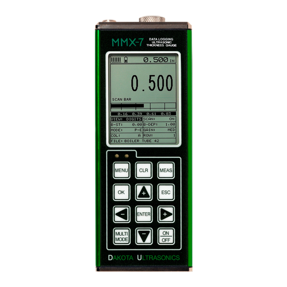
CHAPTER TWO QUICK STARTUP GUIDE Turn the MMX-7 on and off using the switch located on the bottom right corner of the keypad. When MMX-7 is initially turned on, a flash logo and blinking lights will be displayed prior to entering into the main measurement screen. - Page 9 MMX-7 Ultrasonic Thickness Gauge D. Feature Status Bar – Indicates the features currently enabled and in use in the following order: Measurement Mode Differential Mode High Speed Scan Mode Alarm Mode Gain Setting E. Digital Material Thickness Value – Extra large font size for viewing ease.
-
Page 10: Selecting The Transducer Type
Dakota Ultrasonics 2.2 Selecting the Transducer Type The MMX-7 is equipped with a transducer list of all of the dual element transducer options that can be connected to the gauge. These are dual element transducers with different diameters and frequencies, depending on the material and application requirements. -
Page 11: Probe Zero & Calibration
6) Press the OK key to overwrite the existing probe type, or ESC to cancel. 2.3 Probe Zero & Calibration The next steps are to perform a probe zero and calibrate the MMX-7 to the material and transducer selected. If the sound velocity is unknown, the MMX-7 can be... - Page 12 Dakota Ultrasonics Performing a Probe Zero Note: The probe zero disk (battery cap) is located on the top end cap of the gauge. The warning screen will be displayed following the selection and overwrite of a new transducer. 1) Press the OK key to enter the main measurement screen and begin the manual zero process.
- Page 13 MMX-7 Ultrasonic Thickness Gauge 4) Alternatively, press the MENU key once to activate the menu items tab. Press the MENU key multiple times to tab right and the ESC key multiple times to tab left until the PRB menu is highlighted and displaying the submenu items.
- Page 14 Dakota Ultrasonics Note: The value that is displayed will change depending on the current velocity setting in the MMX-7. Disregard the number that is displayed. It is not important. What is important is accurately performing the steps outlined above to insure reliability of the probe zero calculation.
- Page 15 MMX-7 Ultrasonic Thickness Gauge activate the menu items tab. Press the MENU key multiple times to tab right and the ESC key multiple times to tab left until the CAL menu is highlighted and displaying the submenu items. 3) Use the UP and DOWN arrow keys to scroll through the sub menu items until MATL 1PT is highlighted.
-
Page 16: Measure
Dakota Ultrasonics 2.4 Measure The MMX-7 is now ready to measure. There are two different measurement view options each with a specific purpose – Digits & B-Scan. The steps below outline how to toggle between the different view mode options: Selecting the Measurement View Option 1) Press the MENU key once to activate the menu items tab. - Page 17 Once the view has been selected according to the application requirements, the B- Scan Start (B-ST) and Depth (B-DEP) will potentially need adjustment in order to optimize the zoom if the MMX-7 has been set to B-Scan. Use the following steps to adjust these settings directly from the measurement...
- Page 18 Dakota Ultrasonics 2) Press the ENTER key to display the digits edit box. 3) Press the UP and DOWN arrow keys to scroll the highlighted value. 4) Press the LEFT and RIGHT arrow keys to scroll the digit locations. 5) Repeat steps 3 & 4 until the B-ST or B-DEP value is correctly displayed.
-
Page 19: Chapter Three Keyboard, Menu, & Connector Reference
CHAPTER THREE KEYBOARD, MENU, & CONNECTOR REFERENCE 3.1 Menu Key (Operation & Sub Menus) The Menu key activates the primary menu structure containing 8 menu tab groups. These tab groups then contain sub menu items, or functions. The sub menu items have been organized in tab groups according to how closely they are related to the individual tab group names. - Page 20 Dakota Ultrasonics Activating and Getting Around in the Menu Items 1) Press the MENU key once to activate the menu items tab. Press the MENU key multiple times to tab right, and the ESC key multiple times to tab left until the desired tab group is highlighted and displaying the submenu items.
-
Page 21: Probe - Menu
If the MMX-7 is not zeroed correctly, all of the measurements made using the MMX-7 may be in error by some fixed value. The MMX-7 is equipped with an optional automatic or manual zero feature. Refer to the section on page 30, for an explanation of this important procedure. -
Page 22: Disp (Display) - Menu
Dakota Ultrasonics VELOCITY: Function to calibrate the MMX-7 by setting the velocity to a known material velocity. Refer to page 32 for further info. 3.4 DISP (display) – Menu VIEW: Selectable BSCAN (cross section), and DIGITS (large digits) views. Refer to page 42 for further info. -
Page 23: Data - Menu
MMX-7 A/B Scan Thickness Gauge DEFAULT SETUP: Loads a basic default setup. Use only as a last resort when the setups in the MMX-7 have been corrupted and a computer is not accessible. Refer to page 92 for further info. -
Page 24: Xfer (Transfer) - Menu
MMX-7. Refer to page 57 for further info. SHOW DATE: Gives the user the ability to display the date and time in the waveform area of the MMX-7. The options are OFF, DATE, TIME, BOTH. Refer to page 59 for further info. -
Page 25: Ok Key
3.12 ESC Key The ESC key is used in the MENU, MEAS, and EDIT functions as a back or escape function. If the MMX-7 is displaying a grid or sequential log, the ESC key toggles the display options: Digits or B-Scan views. -
Page 26: On/Off Key
Dakota Ultrasonics 3.16 ON/OFF Key The ON/OFF key simply powers the unit either ON or OFF. Note: Unit will automatically power off when idle for 5 minutes. All current settings are automatically saved prior to powering off. -
Page 27: Top & Bottom End Caps
C female connector. It is designed to connect directly from the MMX-7 to a standard USB type A port on a PC. The cable supplied with the MMX-7 is a USB type C to a USB type A (pt# N-003-0330). -
Page 28: Chapter Four Principals Of Ultrasonic Measurement
CHAPTER FOUR PRINCIPALS OF ULTRASONIC MEASUREMENT 4.1 Time versus thickness relationship Ultrasonic thickness measurements depend on measuring the length of time it takes for sound to travel through the material being tested. The ratio of the thickness versus the time is known as the sound velocity. In order to make accurate measurements, a sound velocity must be determined and entered into the instrument. -
Page 29: Temperature
MMX-7 and selecting the ‘zero transducer’ option in the “PRB” menu, or the ‘zero probe’ option in the hot menu items. - Page 30 Dakota Ultrasonics V-Path Correction Dual element delay line transducers have two piezoelectric elements mounted at an angle on one end of the delay line. One element is used for transmitting sound, while the other element only receives sound. The two elements and their delay lines are packaged in a single housing but acoustically isolated from each other with a sound barrier.
- Page 31 MMX-7 A/B Scan Thickness Gauge Dual Element Transducer in Echo to Echo mode...
-
Page 32: Chapter Five Selecting The Measurement Mode
SELECTING THE MEASUREMENT MODE 5.1 The setup library The MMX-7 contains 64 user configurable preset locations to store custom setups for easy recall. These setups can be optimized for common application requirements, and bi-directionally transferred to the gauge and computer using Dakota’s PC or OSX interface software, included with the instrument. -
Page 33: Factory Setup Chart
MMX-7 A/B Scan Thickness Gauge Thin materials Use pulse echo mode and a high frequency transducer for these types of applications. The most common transducers are the 7.5MHz and 10MHz models with extra resolution. The higher frequencies provide greater resolution and a lower minimum thickness rating overall. -
Page 34: Chapter Six Making Measurements
MAKING MEASUREMENTS 6.1 Selecting the Transducer Type The first step in using the MMX-7 is to plug the transducer into the gauge and power up the unit to display the main measurement screen. The diameter and frequency should be noted in order to select a transducer from the list of probes in the gauge. - Page 35 MMX-7 A/B Scan Thickness Gauge 3) Press the ENTER key to display the list of transducer options. 4) Press the UP and DOWN arrow keys to scroll through the transducer list until the appropriate type is highlighted. 5) Press the ENTER key to select the transducer type and display overwrite confirmation screen.
-
Page 36: Probe Zero
If the MMX-7 is not zeroed correctly, all measurements may be in error by some fixed value. In order to perform a zero, the gauge must be set to pulse-echo measurement mode. - Page 37 MMX-7 A/B Scan Thickness Gauge 2) With the “zero probe” hot menu cell highlighted by default, press the ENTER key to display the confirmation screen, followed by pressing the OK key to perform the zero. Note: If the “zero probe” cell is not highlighted, press the MEAS or ESC keys to highlight.
-
Page 38: Material Calibration
6.3 Material Calibration In order for the MMX-7 to make accurate measurements, it must be set to the correct sound velocity of the material being measured. Sound will travel at different speeds in different material types. - Page 39 MMX-7 A/B Scan Thickness Gauge 1) Press the MENU key once to activate the menu items tab. Press the MENU key multiple times to tab right and the ESC key multiple times to tab left until the CAL menu is highlighted and displaying the submenu items.
- Page 40 Dakota Ultrasonics 8) Finally, press the MEAS key to return to the measurement screen and begin taking readings.
- Page 41 As previously discussed, the MMX-7 has a one or two point calibration option. The one point calibration option is most suited for linearity over large ranges, as noted above.
- Page 42 Dakota Ultrasonics ESC key multiple times to tab left until the CAL menu is highlighted and displaying the submenu items. 3) Use the UP and DOWN arrow keys to scroll through the sub menu items until MATL 1PT is highlighted.
- Page 43 MMX-7 A/B Scan Thickness Gauge sample close to .250” (6.35mm), followed by a two point calibration close to .080” (2.03mm). When a two point calibration is performed, the MMX-7 calculates the zero and the velocity. The following steps outline this procedure:...
- Page 44 Dakota Ultrasonics 4) Press the ENTER key to display the Digits Edit Box. 5) Press the UP and DOWN arrow keys to scroll the highlighted value. 6) Press the LEFT and RIGHT arrow keys to scroll the digit locations. 7) Repeat steps 5 & 6 until the known thickness value is correctly displayed.
- Page 45 MMX-7 A/B Scan Thickness Gauge Selecting a Basic Material Type 1) Press the MENU key once to activate the menu items tab. Press the MENU key multiple times to tab right and the ESC key multiple times to tab left until the CAL menu is highlighted and displaying the submenu items.
- Page 46 Dakota Ultrasonics 5) Press the ENTER key to overwrite the material type and display the menu items with the new material type selected. 6) Finally, press the MEAS key to return to the measurement screen and begin taking readings.
-
Page 47: Chapter Seven Using The Display Options
We’ll take a better look at these options in this chapter. Note: In order to recall and use the new adjustments made to the MMX-7 at a later time, the user must save the modified settings in one of the setup locations prior to... -
Page 48: Display Views
MMX-7 is reliably measuring the same value 250 times per second, depending on which measurement mode and features are enabled. B. Battery Icon – Indicates the amount of battery life the MMX-7 has remaining. C. Velocity – The material velocity value the MMX-7 is currently using or calibrated for. - Page 49 MMX-7 A/B Scan Thickness Gauge E. Digital Material Thickness Value – Extra large font size for viewing ease. F. Scan Bar – Another view of material thickness in a deflection style horizontal bar. This is another visual tool that would enable the user the ability to see thickness changes during high speed scans from flaws and pits.
-
Page 50: Changing Display Options
MMX-7 is reliably measuring the same value 250 times per second, depending on which measurement mode and features are enabled. B. Battery Icon – Indicates the amount of battery life the MMX-7 has remaining. C. Velocity – The material velocity value the MMX-7 is currently using or calibrated for. -
Page 51: Adjusting The Display
MMX-7 A/B Scan Thickness Gauge 1) Press the MENU key once to activate the menu items tab. Press the MENU key multiple times to tab right, and the ESC key multiple times to tab left, until the DISP menu is highlighted and displaying the submenu items. - Page 52 Dakota Ultrasonics B-Start 1) Press the MEAS key once to activate measure menu items. Press the MEAS key multiple times to move right and the ESC key multiple times to move left, until the B-ST cell is highlighted. 2) Press the UP, DOWN, LEFT, and RIGHT arrow keys to scroll the highlighted value.
- Page 53 MMX-7 A/B Scan Thickness Gauge The MMX-7 has the capability to adjust the the scrolling speed of the time based B- Scan displayed in the gauge. The procedures to adjust the speed are outlined below: Adjusting the B-Scan Speed 1) Press the MENU key once to activate the menu items tab. Press the MENU key multiple times to tab right, and the ESC key multiple times to tab left, until the DISP menu is highlighted and displaying the submenu items.
-
Page 54: Gain
If it’s turned down too much, you can’t hear it at all. The MMX-7 has a five position gain switch (vlow, low, med, hi, vhi), with Med gain set at 46dB, with an overall cut/boost of 6dB in 3dB increments. The gain can be adjusted to accommodate a variety of material types, and offers the user flexibility. - Page 55 MMX-7 A/B Scan Thickness Gauge The procedures to adjust the Gain are outlined below: Gain Adjust Hot Menu 1) Press the MEAS key once to activate measure menu items. Press the MEAS key multiple times to move right, and the ESC key multiple times to move left until the GAIN cell is highlighted.
- Page 56 Dakota Ultrasonics 2) Use the UP and DOWN arrow keys to scroll through the sub menu items until GAIN is highlighted. 3) Press the LEFT and RIGHT arrow keys to scroll the steps. 4) When the target gain step is displayed, press the MEAS key to return to the...
-
Page 57: Chapter Eight Thru Paint Measurement Technique
8.2 Using Thru Paint Mode By selecting the transducer type from the list of probes stored in the MMX-7, a basic echo-echo thru paint configuration is recalled from memory. Each of the ‘high damped’ transducers in the list contain pre-configured echo-echo settings. However, fine adjustments may be necessary in order to be suitable for your specific applications. -
Page 58: Chapter Nine Additional Features Of The Mmx-7
ADDITIONAL FEATURES OF THE MMX-7 9.1 High Speed Scan The High Speed Scan feature of the MMX-7 increases the overall repetition rate to a maximum of 250Hz with a high speed screen refresh rate of 25 times a second. This... -
Page 59: Alarm Mode
MMX-7 A/B Scan Thickness Gauge 9.2 Alarm Mode The Alarm Mode feature of the MMX-7 provides the user with a method of setting tolerances, or limits, for a particular application requirement. This feature may be used for a variety of applications to verify the material is within the manufacturer specifications. - Page 60 Dakota Ultrasonics 1) Assuming the ALARM is ON, use the UP and DOWN arrow keys to scroll through the sub menu items until ALARM LOW is highlighted. 2) Press the LEFT and RIGHT arrow keys to scroll the value. When the correct alarm value is being displayed, proceed to step 7.
-
Page 61: Differential Mode
MMX-7 A/B Scan Thickness Gauge 9.3 Differential Mode The Differential Mode of the MMX-7 provides the user with the ability to set a nominal value, according to what the expected thickness should be, and measure the +/- difference from the nominal value entered. This feature is typically used in QA incoming inspections on pipes, plate stock, coils, etc. -
Page 62: Key Click
9.4 Key Click When a key is pressed on the MMX-7 keypad, the user can control whether or not an audible beep is sounded and at what volume level, if any. The procedure for this feature/preference is outlined below:... -
Page 63: Set Date & Time
4) Press the MEAS key to return to the measurement screen. 9.5 Set Date & Time The MMX-7 is equipped with an internal clock to time and date stamp the log, setup and screen capture files for reporting/documentation purposes. The procedures for setting the time and date are outlined below: Setting Date &... - Page 64 Dakota Ultrasonics 1) Press the MENU key once to activate the menu items tab. Press the MENU key multiple times to tab right and the ESC key multiple times to tab left until the UTIL menu is highlighted and displaying the submenu items.
-
Page 65: Show Date & Time
9.6 Show Date & Time The MMX-7 can be configured to show the date & time in the active A-Scan window as needed or preferred (off/date/time/both). The procedure for activating and displaying the above options are outlined below: Live Time &... - Page 66 .tif (tagged image) file format that can be opened using any graphics viewer. With the storage capacity of the MMX-7 the user can store as many screens shots as needed. It should also be mentioned that this feature is immediately activated on boot up.
- Page 67 MMX-7 A/B Scan Thickness Gauge 3) Press the ENTER key to display the alpha numeric edit box to name and save the screen shot. 4) Press the MEAS key to return to the measurement screen.
-
Page 68: Chapter Ten Data Storage - Setup, Edit, & View Files
Multiple grids can be created and stored until the MMX-7’s memory is full. If the user attempts to store a new file in the MMX-7 and the size of the file exceeds the capacity of memory, the MMX-7 will respond with an error message indicating that the memory is unable to store the new file. -
Page 69: Creating A New Grid
MMX-7 A/B Scan Thickness Gauge 10.2 Creating a new Grid Grid Name 1) Press the MENU key once to activate the menu items tab. Press the MENU key multiple times to tab right, and the ESC key multiple times to tab left, until the DATA menu is highlighted and displaying the submenu items. - Page 70 Dakota Ultrasonics 5) Press the ENTER key to activate the Alpha Edit Box. 6) Use the UP, DOWN, LEFT, & RIGHT arrow keys to highlight the appropriate alpha characters. 7) Press the ENTER key to select a character and advance to the next field of the grid name.
- Page 71 MMX-7 A/B Scan Thickness Gauge 1) Use the UP and DOWN arrow keys to scroll through the setup options until NOTE is highlighted. 2) Press the ENTER key to activate the Alpha Edit Box. 3) Use the UP, DOWN, LEFT, & RIGHT arrow keys to highlight the appropriate alpha characters.
- Page 72 Dakota Ultrasonics Setting the Coordinates or Start & Stop ID’s A grid is defined by using coordinates to define the Top Left and the Bottom Right corners of the grid. Alpha coordinates are horizontal across the top, and numeric coordinates are vertical down the side. Therefore, to define the top left corner of the grid, there will be an (X,Y) coordinate.
- Page 73 MMX-7 A/B Scan Thickness Gauge 3) Use the LEFT and RIGHT arrow keys to scroll the Columns, and the UP and DOWN arrow keys to scroll the Rows. 4) Press the OK key to select the coordinate and return to the setup list, or ESC to cancel setting the coordinate.
- Page 74 Dakota Ultrasonics 2) Press the ENTER key to activate the Coordinate Edit Box. 3) Use the LEFT, & RIGHT arrow keys to scroll the Columns, and the UP and DOWN arrow keys to scroll the Rows. 4) Press the OK key to select the coordinate and return to the setup list, or ESC to cancel the selection and return to the setup list.
- Page 75 MMX-7 A/B Scan Thickness Gauge Auto Increment Direction The Auto Increment feature gives the user the ability to specify which direction to advance the cursor after storing a reading. 5) Use the UP and DOWN arrow keys to scroll through the setup list until INCR.
- Page 76 Dakota Ultrasonics 1) Use the UP and DOWN arrow keys to scroll through the setup list until CREATE GRID is highlighted. 2) Press the ENTER key to save the grid display the confirmation screen. 3) Press the OK key to save the Grid, or the ESC key to cancel the setup and return to the DATA menu.
-
Page 77: Storing A Reading
MMX-7 A/B Scan Thickness Gauge 10.3 Storing a reading Now that a grid or sequential log has been created, it’s time to make some measurements and store the readings. The following procedures outline this process: Storing Data Note: Once the gird has been created it will automatically be displayed following the create confirmation screen. -
Page 78: Viewing Stored Readings
If the gauge is powered off, the will automatically open the file when powered on. 10.4 Viewing stored readings It is sometimes necessary to go back and view the stored readings and B-Scans using the MMX-7 without a PC. The following procedures outline this process:... - Page 79 MMX-7 A/B Scan Thickness Gauge Viewing Stored Readings & A/B Scans 1) Press the MEAS key once to activate measure menu items. Press the MEAS key multiple times to move right and the ESC key multiple times to move left until the LOG cell is highlighted.
-
Page 80: Deleting Grids (Files)
Dakota Ultrasonics 4) The user may opt to clear a specific reading and save a new one at any time. Press the CLR key in the appropriate cell location to clear the reading, take a new measurement, and press the ENTER key to save the new reading. - Page 81 MMX-7 A/B Scan Thickness Gauge 3) Press the ENTER key to display the File List Box. 4) Use the UP and DOWN arrow keys to scroll through the stored Files until the target File to delete is highlighted. 5) Press the OK key to delete the File.
- Page 82 Dakota Ultrasonics 2) Use the UP and DOWN arrow keys to scroll through the sub menu items until DELETE ALL DATA is highlighted. 3) Press the ENTER key to activate the confirmation screen. 4) Press the OK key to delete All Files from memory, or the ESC key to abort.
-
Page 83: Editing A Grid (File)
MMX-7 A/B Scan Thickness Gauge 10.6 Editing a Grid (File) Once a grid has been created and saved to memory, the user can edit the Comments or Increment Direction at a later time. The following procedures outline this process: Editing a Grid 1) Press the MENU key once to activate the menu items tab. - Page 84 Dakota Ultrasonics 5) Press the ENTER key to activate the Alpha Edit box – Only used when editing the NOTE. 6) Use the UP, DOWN, LEFT, & RIGHT arrow keys to highlight the appropriate alpha characters. 7) Press the ENTER key to select a character and advance to the next field of the Comments.
-
Page 85: Changing The Active File - Open
The user may have transferred grid templates from a PC to the MMX-7, or setup grids using the MMX-7 at an earlier time. The name of the currently active file is always displayed at the top of the Grid Box in measurement mode (refer to photo below). - Page 86 Dakota Ultrasonics 1) Press the MENU key once to activate the menu items tab. Press the MENU key multiple times to tab right and the ESC key multiple times to tab left until the DATA menu is highlighted and displaying the submenu items.
-
Page 87: Closing An Active File - Close
MMX-7 A/B Scan Thickness Gauge 3) Press the ENTER key to display the Grid/Seq List Box. 4) Use the UP and DOWN arrow keys to scroll through the grids until the target grid is highlighted. 5) Press the ENTER key to activate the confirmation screen. - Page 88 Dakota Ultrasonics A user might not have a current requirement to store measurements, but a file is currently open or active and needs to be closed. The following procedures outline how to close an open or active file: Close an Active File 1) Press the MENU key once to activate the menu items tab.
- Page 89 MMX-7 A/B Scan Thickness Gauge 3) Press the ENTER key to close the active file. Note: Following the key press, the CLOSE text will be grayed out indicating the file has been close and is no longer active.
-
Page 90: Chapter Eleven Setups - Create, Store, Edit, & Recall
The MMX-7 can store up to 64 custom setups. These setups can be bi-directionally transferred to and from a PC. Therefore, the user can save as many setups as necessary for all their individual applications requirements. - Page 91 MMX-7 A/B Scan Thickness Gauge 1) Press the MENU key once to activate the menu items tab. Press the MENU key multiple times to tab right and the ESC key multiple times to tab left until the SETUP menu is highlighted and displaying the submenu items.
-
Page 92: Saving A Setup
7) Press the MEAS key to return to the measure screen. 11.3 Saving a Setup Once the MMX-7 parameters and features have be adjusted for an application, the user may elect to save these setting to a specific setup location for future use. This can potentially save time and reduce error between users. - Page 93 MMX-7 A/B Scan Thickness Gauge 1) Press the MENU key once to activate the menu items tab. Press the MENU key multiple times to tab right and the ESC key multiple times to tab left until the SETUP menu is highlighted and displaying the submenu items.
- Page 94 Dakota Ultrasonics 5) When the parameter to edit is highlighted, press the ENTER key to activate the Alpha Edit Box. 6) Use the UP, DOWN, LEFT, and RIGHT arrow keys to scroll through the characters, the ENTER key to select characters, and the CLR key to backspace through the characters, until the Name or Note fields have been edited.
- Page 95 MMX-7 A/B Scan Thickness Gauge 11) Use the UP and DOWN arrow keys to scroll through the setups until the target location to save the Setup is highlighted. 12) Press the OK key to activate the confirmation screen. 13) Press the OK key to save the Setup, or ESC to cancel saving the Setup.
-
Page 96: Deleting A Saved Setup
Dakota Ultrasonics 11.4 Deleting a Saved Setup This option allows a user to delete setup files that were previously saved and no longer needed. It’s a simple feature to allow the user to do a bit of “house cleaning”. Delete Setup 1) Press the MENU key once to activate the menu items tab. - Page 97 MMX-7 A/B Scan Thickness Gauge 3) Press the ENTER key to display the Setups List. 4) Press the UP and DOWN arrow keys to scroll to the Setup Name. 5) When the Setup Name is highlighted, press the ENTER key to display the confirmation screen.
-
Page 98: Using The Default Setup
Dakota Ultrasonics 11.5 Using the Default Setup The default setup feature was added to the MMX-7 to use, as a last resort, if there are no setups stored in the gauge –factory or otherwise. The only time this might possibly occur is if the setup file in the MMX-7 was somehow corrupted, and the user does not have access to a computer to re-load the factory setups back into the MMX- 7. -
Page 99: Selecting A Language
MMX-7 A/B Scan Thickness Gauge 11.6 Selecting a Language The MMX-7 is equipped with a language option. Currently, the only languages supported are English, Spanish, German, French, Hungarian, Czech, however the list continues to grow. Check with Dakota for an updated list. The steps to select one of... -
Page 100: Chapter Twelve Using The Utility Software
12.5 Upgrading the MMX-7 The MMX-7 can be upgraded to the latest revision of firmware at any time. Simply download the latest version posted on the Dakota Ultrasonics website, copy the upgrade file to the main drive directory MMX-7, and use the upgrade utility located in the XFER menu. - Page 101 MMX-7 A/B Scan Thickness Gauge Upgrading the Firmware 1) Press the MENU key once to activate the menu items tab. Press the MENU key multiple times to tab right and the ESC key multiple times to tab left until the XFER menu is highlighted and displaying the submenu items.
-
Page 102: Appendix A - Velocity Table
APPENDIX A - VELOCITY TABLE Material sound velocity sound velocity in/us Aluminum 0.2510 6375 Beryllium 0.5080 12903 Brass 0.1730 4394 Bronze 0.1390 3531 Cadmium 0.1090 2769 Columbium 0.1940 4928 Copper 0.1830 4648 Glass (plate) 0.2270 5766 Glycerine 0.0760 1930 Gold 0.1280 3251 Inconel... - Page 103 MMX-7 A/B Scan Thickness Gauge 0.1310 3327 Titanium 0.2400 6096 Tungsten 0.2040 5182 Uranium 0.1330 3378 Water 0.0580 1473 Zinc 0.1660 4216 Zirconium 0.1830 4648...
-
Page 104: Appendix B - Setup Library
APPENDIX B - SETUP LIBRARY Name Comment 1 Gn/AGC Velocity Enter Custom Name … … … … … … …... - Page 105 Additionally, Dakota Ultrasonics warrants transducers and accessories against such defects for a period of 90 days from receipt by the end user. If Dakota Ultrasonics receives notice of such defects during the warranty period, Dakota Ultrasonics will either, at its option, repair or replace products that prove to be defective.
Need help?
Do you have a question about the MMX-7 and is the answer not in the manual?
Questions and answers