
Related Manuals for DAKOTA ULTRASONICS PX-7


Summary of Contents for DAKOTA ULTRASONICS PX-7
- Page 1 OPERATION MANUAL DAKOTA ULTRASONICS MODEL PX-7 PRECISION THICKNESS GAUGE P/N P-129-0002 Rev1.60 January 2008 1.800.561.8187 information@itm.com www. .com...
- Page 2 Dakota Ultrasonics. Every precaution has been taken in the preparation of this publication. Dakota Ultrasonics assumes no responsibility for errors or omissions. Neither is any liability assumed for damages resulting from the use of information contained herein.
- Page 3 PX-7 Ultrasonic Thickness Gauge CONTENTS NTRODUCTION PERATION EYPAD ISPLAY RANSDUCER AKING EASUREMENTS ONDITION AND REPARATION OF URFACES & ELECTING EASUREMENT THE LOCK MODE ALIBRATION , RS232 P LARM RANSDUCER ELECTION A: P PPENDIX RODUCT PECIFICATIONS B: A PPENDIX PPLICATION OTES...
- Page 4 This manual is presented in three sections. The first s ection covers operation of the PX-7, and explains the keypad controls and display. The second section provides guidelines in selecting a transducer for a specific application. The last section provides application notes and a table of sound velocity values for various materials.
-
Page 5: Operation
The Keypad This key is used to turn the PX-7 on and off. When the tool is turned ON, it will first perform a brief display test by illuminating all of the segments in the display. After one second, the tool will display the internal software version number. - Page 6 Dakota Ultrasonics The CAL key is used to enter and exit the PX-7's calibration mode. This mode is used to adjust the sound-velocity value that the PX-7 will use when calculating thickness. The tool will either calculate the sound-velocity from a sample of the material being measured, or allow a known velocity value to be entered directly.
- Page 7 The SCAN key switches the SCAN measurement mode on and off. Refer to page 17 for an explanation of the SCAN measurement mode. The DOWN arrow key has three functions. When the PX-7 is in the CAL mode, this key is used to decrease numeric values on the display. An auto-repeat function is built in, so that when the key is held down, numeric values will decrement at an increasing rate.
- Page 8 Dakota Ultrasonics The ALRM key has two functions. By holding down the ALRM key when powering up the PX-7, the audible beeper will be turned on or off accordingly. After the unit has been turned on, pressing the ALRM key will toggle the alarm mode to the on/off positions and allow the user to enter a nominal thickness value.
-
Page 9: The Display
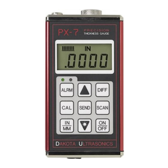
When this occurs, the batteries should be replaced. These eight vertical bars form the Stability Indicator. When the PX-7 is idle, only the left-most bar and the underline will be on. While the gauge is taking a measurement, six or seven of the bars should be on. - Page 10 Dakota Ultrasonics When the IN symbol is on, the PX-7 is displaying a thickness value in inches. The maximum thickness that can be displayed is 1.0000 inches. When the MM symbol is on, the PX-7 is displaying a thickness value in millimeters.
-
Page 11: T He T Ransducer
The transducer connects to the PX-7 via the attached cable, and one coaxial connector. The transducer must be used correctly in order for the PX-7 to produce accurate, reliable measurements. Below is a short description of the transducer, followed by instructions for its use. -
Page 12: Making Measurements
The Stability Indicator should have six or seven bars darkened, and a number should appear in the display. If the PX-7 has been set to the correct sound velocity (see page 14), the number in the display will indicate the actual thickness of the material directly beneath the transducer. - Page 13 Occasionally, a small film of couplant will be drawn out between the transducer and the surface as the transducer is removed. When this happens, the PX-7 may perform a measurement through this couplant film, resulting in a measurement that is larger or smaller than it should be. This...
-
Page 14: C Ondition And P Reparation Of S Urfaces
Dakota Ultrasonics Condition and Preparation of Surfaces In any ultrasonic measurement scenario, the shape and roughness of the test surface are of paramount importance. Rough, uneven surfaces may limit the penetration of ultrasound through the material, and result in unstable, and therefore unreliable, measurements. The surface being measured should be clean, and free of any small particulate matter, rust, or scale. - Page 15 Note: Once the mode has been selected, the user can use the built-in LOC feature to prevent additional users from accidentally changing the mode. When the PX-7 is in LOC mode, all features (with the exception of the calibration and units), are locked and cannot be 1.800.561.8187...
-
Page 16: C Alibration
PX-7 to toggle the LOC feature on/off. Repeat procedure to toggle on/off status. Calibration In order for the PX-7 to make accurate measurements, it must be set to the correct sound-velocity for the material being measured. Different types of material have different inherent sound-velocities. For example, the velocity of sound through steel is about 0.233 inches-per-microsecond,... - Page 17 7) Press the CAL key again. The IN/µ s (or M/s) symbols should begin flashing. The PX-7 is now displaying the sound velocity value it has calculated based on the thickness value that was entered in step 6.
- Page 18 (0.233 IN/µs). To achieve the most accurate measurements possible, it is generally advisable to always calibrate the PX-7 to a sample piece of known thickness. Material composition (and thus, its sound-velocity) sometimes varies from lot to lot and from manufacturer to manufacturer. Calibration to a sample of known thickness will ensure that the tool is set as closely as possible to the sound velocity of the material to be measured.
- Page 19 While the PX-7 excels at making single point measurements, it is sometimes desirable to examine a larger region, searching for the thinnest point. The PX-7 includes a feature, called Scan Mode, which allows it to do just that. In normal operation, the PX-7 performs and displays four measurements every second, which is quite adequate for single measurements.
- Page 20 Dakota Ultrasonics Alarm Mode The Alarm Mode feature of the PX-7 allows the user to set an audible and visual Hi / Lo parameter when taking measurements. If the measurement falls below or above the Hi / Lo limits, set by the user, a red light will be illuminated on the front panel of the gauge and the beeper sounded.
- Page 21 5) Press the SEND key to select the Lo value entered. The Hi value will now be displayed. Repeat step 4 select the Hi alarm value. 6) The PX-7 is now ready to perform measurements using the Alarm feature. Differential Mode...
-
Page 22: Differential Mode
(part# N-306-0010), the PX-7 has the ability to connect to a computer, or external storage device. The following section outlines the procedure for connecting the PX-7 to a computer, and how to collect data using any standard communications program: 1.800.561.8187... - Page 23 Connecting To a Computer 1) Connect the accessory cable (part# N-306-0010) to the 2 pin jack located on the bottom of the PX-7, and the 9 pin connector to a serial port on the computer. 2) Start the communications software that will be used to collect the measurements (i.e.
-
Page 24: Transducer Selection
As ultrasound travels through any material, it is partly absorbed. If the material through which the sound travels has any grain structure, the sound waves will experience scattering. Both of these effects reduce the strength of the waves, and thus, the PX-7's ability to detect the returning echo. 1.800.561.8187 information@itm.com... - Page 25 It may be necessary to experiment with a variety of transducers in order to find one that works well for a given job. Dakota Ultrasonics can provide assistance in choosing a transducer, and offers a broad selection of transducers for evaluation in specialized applications.
- Page 26 PX-7 Ultrasonic Thickness Gauge APPENDIX A Product Specifications Physical Weight: 10 ounces(with batteries). Size: 2.5W x 4.5 H x 1.24 D inches (63.5W x 114.3 H x 31.5 D mm). Operating Temperature: -20 to 120 °F ( -30 to 50 °C) Case: Extruded aluminum body / nickel plated aluminum end caps.
- Page 27 (refer to page 14) on a sample piece of known thickness, which is at or near the temperature of the material to be measured. This will allow the PX-7 to correctly calculate the velocity of sound through the hot material.
- Page 28 Dakota Ultrasonics a time as needed to acquire a stable measurement. While the transducer is in contact with a hot surface, it will begin to heat up, and through thermal expansion and other effects, may begin to adversely affect the accuracy of measurements.
- Page 29 PX-7 Ultrasonic Thickness Gauge APPENDIX C Sound Velocities of some Common Materials M a t e r i a l s o u n d v e l o c i t y i n / u s m / s A l u m i n u m 0 .
-
Page 30: Warranty Information
Dakota Ultrasonics warrants the PX-7 against defects in materials and workmanship for a period of five years from receipt by the end user. Additionally, Dakota Ultrasonics warrants transducers and accessories against such defects for a period of 90 days from receipt by the end user. - Page 31 MATERIAL SAFETY DATA SHEET N/A = not applicable or not available (To comply with 29 CFR 1910.1200) SECTION 1 – PRODUCT IDENTIFICATION NFPA Hazardous Materials Product Name: SOUNDSAFE® Identification System (est) Generic Name: Ultrasonic Couplant Health……………………0 Manufacturer: Sonotech, Inc. Flammability…………….0 774 Marine Dr., Bellingham, WA 98225 Reactivity………………..0 (360) 671-9121...
Need help?
Do you have a question about the PX-7 and is the answer not in the manual?
Questions and answers