
Related Manuals for DAKOTA ULTRASONICS MX-2


Summary of Contents for DAKOTA ULTRASONICS MX-2
- Page 1 OPERATION MANUAL DAKOTA ULTRASONICS MODEL MX-2 ULTRASONIC THICKNESS GAUGE P/N P-140-0002 Rev 1.90, August 2008 1.800.561.8187 information@itm.com www. .com...
- Page 2 Dakota Ultrasonics. Every precaution has been taken in the preparation of this publication. Dakota Ultrasonics assumes no responsibility for errors or omissions. Neither is any liability assumed for damages resulting from the use of information contained herein.
- Page 3 MX-2 Ultrasonic Thickness Gauge CONTENTS NTRODUCTION PERATION EYPAD ISPLAY RANSDUCER AKING EASUREMENTS ONDITION AND REPARATION OF URFACES ROBE ALIBRATION MX-2’ ROGRAMMING OUND ELOCITY RANSDUCER ELECTION A: P PPENDIX RODUCT PECIFICATIONS B: A PPENDIX PPLICATION OTES C: S PPENDIX OUND ELOCITIES OF...
- Page 4 This manual is presented in three sections. The first section covers operation of the MX-2, and explains the keypad controls and display. The second section provides guidelines in selecting a transducer for a specific application. The last section provides application notes and a table of sound velocity values for various materials.
-
Page 5: Operation
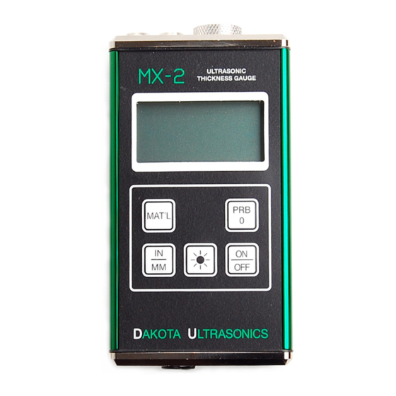
This key is used to turn the MX-2 on and off. When the gauge is turned ON, it will first perform a brief display test by illuminating all of the segments in the display. - Page 6 Dakota Ultrasonics The PRB-0 key is used to "zero" the MX-2 in much the same way that a mechanical micrometer is zeroed. If the gauge is not zeroed correctly, all of the measurements that the gauge makes may be in error by some fixed value.
- Page 7 Materials of the same type may have slightly different material velocities introducing error into the overall measurement. Note: The material types hard set in the MX-2 are listed by type, abbreviation, and velocity on the back of the MX-2.
- Page 8 When the gauge is making a measurement, six or seven of the bars should be on. If fewer than five bars are on, the MX-2 is having difficulty achieving a stable measurement, and the thickness value displayed will most likely be erroneous.
- Page 9 MX-2 Ultrasonic Thickness Gauge When the IN symbol is on, the MX-2 is displaying a thickness value in inches. The maximum thickness that can be displayed is 19.999 inches. When the MM symbol is on, the MX-2 is displaying a thickness value in millimeters.
- Page 10 MX-2. The transducer must be used correctly in order for the MX-2 to produce accurate, reliable measurements. Below is a short description of the transducer, followed by instructions for its use.
- Page 11 The Stability Indicator should have six or seven bars darkened, and a number should appear in the display. If the MX-2 has been properly "zeroed" (see page 12) and set to the correct 1.800.561.8187 information@itm.com...
- Page 12 While the transducer is in contact with the material being measured, the MX-2 will perform four measurements every second, updating its display as it does so. When the transducer is removed from the surface, the display will hold the last measurement made.
- Page 13 MX-2 Ultrasonic Thickness Gauge Condition and Preparation of Surfaces In any ultrasonic measurement scenario, the shape and roughness of the test surface are of paramount importance. Rough, uneven surfaces may limit the penetration of ultrasound through the material, and result in unstable, and therefore unreliable, measurements.
- Page 14 Dakota Ultrasonics Probe Zero Setting the Zero Point of the MX-2 is important for the same reason that setting the zero on a mechanical micrometer is important. If the gauge is not "zeroed" correctly, all of the measurements the gauge makes will be in error by some fixed number.
- Page 15 This will ensure that the instrument is always correctly zeroed. Calibration In order for the MX-2 to make accurate measurements, it must be set to the correct sound-velocity for the material being measured. Different types of material have different inherent sound-velocities. For example, the velocity of sound through steel is about 0.233 inches-per-microsecond,...
- Page 16 Since the MX-2 is a fixed velocity gauge with 8 factory set material types, correct sound velocity for the material being measured must be selected using one of the 8 materials in the MX-2, or programmed into the gauge via the serial port on the bottom of the unit. Approximate sound velocities for common materials can be found in appendix C.
- Page 17 5) Click on the Program Gauge button located in the top right of the window. A pop up window will be display with the following message “Turn on gauge power”. Press the ON/OFF button on the MX-2 to download the velocity. The MX-2 will display the new velocity. 1.800.561.8187 information@itm.com...
-
Page 18: Transducer Selection
Generally speaking, the best transducer for a job is one that sends sufficient ultrasonic energy into the material being measured such that a strong, stable echo is received by the MX-2. Several factors affect the strength of ultrasound as it travels. These are outlined below: •... - Page 19 MX-2 Ultrasonic Thickness Gauge strength of the waves, and thus, the MX-2's ability to detect the returning echo. Higher frequency ultrasound is absorbed and scattered more than ultrasound of a lower frequency. While it may seem that using a lower frequency transducer might be better in every instance, low frequencies are less directional than high frequencies.
- Page 20 Dakota Ultrasonics Selection of the proper transducer is often a matter of tradeoffs between various characteristics. It may be necessary to experiment with a variety of transducers in order to find one that works well for a given job. Dakota Ultrasonics can provide assistance in choosing a transducer, and offers a broad selection of transducers for evaluation in specialized applications.
- Page 21 MX-2 Ultrasonic Thickness Gauge APPENDIX A Product Specifications Physical Weight: 10 ounces Size: 2.5W x 4.75H x 1.25D inches (63.5W x 120.7H x 31.8D mm). Operating Temperature: -20 to 120 °F (-20 to 50 °C) Case: Extruded aluminum body / nickel plated aluminum end caps.
- Page 22 MX-2 Ultrasonic Thickness Gauge APPENDIX B Application Notes • Measuring pipe and tubing When measuring a piece of pipe to determine the thickness of the pipe wall, orientation of the transducers is important. If the diameter of the pipe is larger than approximately 4 inches, measurements should be made with the transducer oriented so that the gap in the wearface is perpendicular (at right angle) to the long axis of the pipe.
- Page 23 (refer to page 11) on a sample piece of known thickness, which is at or near the temperature of the material to be measured. This will allow the MX-2 to correctly calculate the velocity of sound through the hot material.
- Page 24 MX-2 Ultrasonic Thickness Gauge An additional important consideration when measuring laminates, is that any included air gaps or pockets will cause an early reflection of the ultrasound beam. This effect will be noticed as a sudden decrease in thickness in an otherwise regular surface. While this may impede accurate measurement of total material thickness, it does provide the user with positive indication of air gaps in the laminate.
- Page 25 MX-2 Ultrasonic Thickness Gauge APPENDIX C Sound Velocities of some Common Materials M a t e r i a l s o u n d v e l o c i t y i n / u s m / s A l u m i n u m 0 .
-
Page 26: Warranty Information
Dakota Ultrasonics warrants transducers and accessories against such defects for a period of 90 days from receipt by the end user. If Dakota Ultrasonics receives notice of such defects during the warranty period, Dakota Ultrasonics will either, at its option, repair or replace products that prove to be defective.
Need help?
Do you have a question about the MX-2 and is the answer not in the manual?
Questions and answers