
Related Manuals for DAKOTA ULTRASONICS DFX-7


Summary of Contents for DAKOTA ULTRASONICS DFX-7
- Page 1 OPERATION MANUAL DAKOTA ULTRASONICS Material & Coating Thickness Gauge (Manual 1 of 2) P/N P-220-0007 Rev 2.0, July 2017...
-
Page 3: Table Of Contents
CONTENTS CHAPTER ONE INTRODUCTION ..............1 1.1 G ......................1 ENERAL ISCLAIMER CHAPTER TWO QUICK STARTUP GUIDE ............2 2.1 DFX-7 O ........................ 2 VERVIEW 2.2 A ....................5 ROBE ECOGNITION 2.3 S ..................6 ELECTING THE RANSDUCER 2.4 P &... - Page 4 ....................34 RANSDUCER ONNECTORS & B ..................34 ROBE ATTERY OVER USB-C C ........................ 34 ONNECTOR CHAPTER FOUR PRINCIPALS OF ULTRASONIC MEASUREMENT ... 35 4.1 T ................35 IME VERSUS THICKNESS RELATIONSHIP 4.2 S ....................35 UITABILITY OF MATERIALS 4.3 R .................
- Page 5 EASUREMENT 9.6 T (CT) ................103 OINT OATING ALIBRATION ........................ 103 NOWN HICKNESS CHAPTER TEN ADDITIONAL FEATURES OF THE DFX-7 ......108 10.1 B ........................108 RIGHTNESS 10.2 C ......................... 109 OLORS 10.3 LANDSCAPE (A-S ) ....................111 10.4 DIM ..........................112 10.5 G...
- Page 6 13.1 C ................169 OMPUTER YSTEM EQUIREMENTS 13.2 I ..................... 169 NSTALLING 13.3 C DFX-7 ................. 169 OMMUNICATING WITH THE 13.4 U DFX-7 ....................169 PGRADING THE APPENDIX A - VELOCITY TABLE ..............171 APPENDIX B - SETUP LIBRARY ..............173...
-
Page 9: Chapter One Introduction
The Dakota Ultrasonics model DFX-7 is both, an ultrasonic thickness gauge, as well as a flaw detector. Since the DFX-7 is basically two gauges in a single package, we split the manual into two manuals, one for each gauge type. This manual will focus only on the thickness gauge portion of the gauge. -
Page 10: Chapter Two Quick Startup Guide
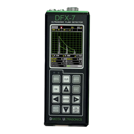
CHAPTER TWO QUICK STARTUP GUIDE Turn the DFX-7 on and off using the switch located on the bottom right corner of the keypad. When DFX-7 is initially turned on, a flash logo and blinking lights will be displayed, followed by attempting to identify the transducer (probe) currently plugged into the gauge. - Page 11 DFX-7 Ultrasonic Flaw Detector In order to understand how to operate the DFX-7, it’s best to start off with an understanding of what it is we’re looking at exactly. The DFX-7 has a lot of great features and tools that will prove to be a huge benefit for the variety of applications you’re constantly facing on a continual basis.
- Page 12 Dakota Ultrasonics F. Scan Bar – Another view of material thickness in a deflection style horizontal bar. This is a visual tool that would enable the user the ability to see thickness changes during high speed scans from flaws and pits.
-
Page 13: Auto Probe Recognition
DFX-7 Ultrasonic Flaw Detector 2.2 Auto Probe Recognition When the DFX-7 is initially powered up, the gauge will automatically check to see if the transducer plugged into the gauge can be recognized. The steps that follow assume the DFX-7 recognized the probe type:... -
Page 14: Selecting The Transducer Type
& Calibration section outlined below. 2.3 Selecting the Transducer Type If the DFX-7 does not identify a specific transducer type on initial power up, the user will be required to select a type from a predefined list of types by diameter and frequency. - Page 15 DFX-7 Ultrasonic Flaw Detector Selecting the Transducer Type 1) Press the OK or ESC keys to display the factory list of transducer types (by diameter and frequency). 2) Press the UP and DOWN arrow keys to scroll through the transducer list...
-
Page 16: Probe Zero & Calibration
2.4 Probe Zero & Calibration The next steps are to perform a probe zero and calibrate the DFX-7 to the material and transducer being used. If the sound velocity is unknown, the DFX-7 can be calibrated to a known thickness sample. - Page 17 2) Press the OK key to perform the automatic probe zero, or ESC key to cancel the zero operation. Coating Probe Identified Coating Probe Not Identified 3) The screens illustrated above will be briefly displayed followed by the main measurement screen. The DFX-7 is ready to be calibrated.
- Page 18 Dakota Ultrasonics Performing a Manual Probe Zero (On Block) Note: When the zero probe option is set to manual, the probe zero disk (battery cap) located on the top of the gauge, will be used as a zero standard and the warning screen illustrated above will be displayed.
-
Page 19: One Point Material Calibration
Note: The value that is displayed will change depending on the current velocity setting in the DFX-7. Disregard the number that is displayed. It is not important. What is important is accurately performing the steps outlined above to insure reliability of the probe zero calculation. - Page 20 Dakota Ultrasonics Using a Known Thickness Note: Be sure that the probe zero procedure has been performed prior to performing this calibration procedure. 1) Physically measure an exact sample of the material or a location directly on the material to be measured using a set of calipers or a digital micrometer.
-
Page 21: Zero Coating
2.5 Zero Coating In order to account for very slight electronic differences in transducers of the same type, frequency, and diameter, the DFX-7 has been equipped with a “zero coating” feature. This enables the DFX-7 to obtain very accurate readings on coatings, eliminating potential errors incurred from slight differences in the manufacturing processes. - Page 22 Dakota Ultrasonics Performing a Coating Zero 1) Press the MULTI MODE key once to activate the measurement mode options. 2) Use the UP and DOWN arrow keys to scroll through the sub menu items until Coating Only (CT) mode is highlighted.
-
Page 23: Coating Calibration
If the velocity of the coating is known, and different than the above default setting, the user can simply enter the coating velocity into the DFX-7. However, if the velocity is unknown, the DFX-7 can also be calibrated to a specific coating sample/type using the 1pt calibration option in PECT (pulse-echo coating) -
Page 24: Known Coating Velocity
If the coating velocity is known, the user may wish to simply enter the velocity number into the DFX-7, rather than have the DFX-7 calculate the velocity value using a known thickness on a coating sample. The steps for entering the velocity are... -
Page 25: Known Coating Thickness
It would be very handy to carry a set of mechanical calipers to use in conjunction with the DFX-7 for calibration in the field: Using a Coating Sample to Calibrate 1) Physically measure a location on a coating sample using a set of calipers or a digital micrometer. - Page 26 Dakota Ultrasonics Important Note: In PECT (pulse-echo coating) mode, the coating sample must be coupled to metal in order to calibrate successfully. Simply place a drop of couplant on a piece of metal, lay the coating sample over the couplant on the metal and proceed to step 2.
-
Page 27: Measure
2.7 Measure The DFX-7 is now ready to measure. There are four different measurement view options, each with a specific purpose – Digits, RF, RECT, & B-Scan. The steps below outline how to toggle between the different view mode options: Selecting the Measurement View Option 1) Press the MENU key once to activate the menu items tab. - Page 28 DIGITS: Displays the digital thickness value using a large font size. This view is useful when the DFX-7 is being used as a basic thickness gauge. RF: Displays the actual waveform signal, much like an oscilloscope, from the reflection of the opposite surface, pit, flaw, crack or void. This view shows both the positive and negative peaks, and is often used to fine tune the scope settings, prior to inspection.
- Page 29 DFX-7 Ultrasonic Flaw Detector Adjusting Delay (B-Start) & Range (B-DEPTH) 1) Press the MEAS key once to activate the measure menu items. Press the MEAS key multiple times to move right and the ESC key multiple times to move left, until the either the DELAY (START) or RANGE (DEPTH) cell is highlighted.
- Page 30 Dakota Ultrasonics 1) Press the ENTER key to display the digits edit box. 2) Press the UP and DOWN arrow keys to scroll the highlighted value. 3) Press the LEFT and RIGHT arrow keys to scroll the digit locations. 4) Repeat steps 3 & 4 until the DELAY (START) or RANGE (DEPTH) value is correctly displayed.
- Page 31 65 measurements a second in scan mode. When the DFX-7 is idle, only the left vertical bar will be displayed. However, when the DFX-7 is making a measurement, four or five of the bars should be displayed on the repeatability indicator.
-
Page 32: Chapter Three Keyboard, Menu, & Connector Reference
CHAPTER THREE KEYBOARD, MENU, & CONNECTOR REFERENCE 3.1 Menu Key (Operation & Sub Menus) The Menu key activates the primary menu structure containing 8 menu tab groups. These tab groups then contain sub menu items, or functions. The sub menu items have been organized in tab groups according to how closely they are related to the individual tab group names. - Page 33 DFX-7 Ultrasonic Thickness Gauge Activating and Getting Around in the Menu Items 1) Press the MENU key once to activate the menu items tab. Press the MENU key multiple times to tab right, and the ESC key multiple times to tab left until the desired tab group is highlighted and displaying the submenu items (B).
-
Page 34: Probe - Menu
If the DFX-7 is not zeroed correctly, all of the measurements made using the DFX-7 may be in error by some fixed value. The DFX-7 is equipped with an optional automatic or manual zero feature. Refer to the section on page 47, for an explanation of this important procedure. -
Page 35: Disp (Display) - Menu
Refer to page 103 for further info. COATING VEL: Function to calibrate the DFX-7 to a specific coating material type by entering a coating velocity. Refer to page 16 or page 97 for further info. -
Page 36: Tune - Menu
Refer to page 119 for further info. GAIN: The DFX-7 has 100dB gain range from (-30 to 70 dB), used in conjunction with the attenuator feature above. This feature is used to increase/decrease the power or amplitude of the signal. -
Page 37: Gt1 - Menu
DFX-7 Ultrasonic Thickness Gauge 3.6 GT1 – Menu GATE1: Gates allow the user to view a specific measurement range, or sections of the waveform, and ignore others. The Gate1 feature adjusts the start of the gate, according to time/distance. Gate 1 can be used in all pulse-echo and echo-echo measurement modes. -
Page 38: Setup - Menu
Refer to page 165 for further info. DEFAULT SETUP: Loads a basic default setup. Use only as a last resort when the setups in the DFX-7 have been corrupted and a computer is not accessible. Refer to page 166 for further info. -
Page 39: Util (Utilities) - Menu
Refer to page 123 for further info. DIFFERENTIAL: Gives the user the ability to set a nominal value and the DFX-7 will display +/- the difference from the nominal value entered. Refer to page 126 for further info. -
Page 40: Xfer (Transfer) - Menu
DFX-7. Refer to page 128 for further info. SHOW DATE: Gives the user the ability to display the date and time in the waveform area of the DFX-7. The options are OFF, DATE, TIME, BOTH. Refer to page 130 for further info. -
Page 41: Esc Key
The ESC key is used in the MENU, MEAS, and EDIT functions as a back or escape function. If the DFX-7 is displaying a grid or sequential log, the OK key toggles the display options: Digits, RF, RECT, and B-Scan views. -
Page 42: Top & Bottom End Caps
C female connector. It is designed to connect directly from the DFX-7 to a standard USB type A port on a PC. The cable supplied with the DFX-7 is a USB type C to a USB type A (pt# N-003-0330). Note: This connector is also used to upgrade... -
Page 43: Chapter Four Principals Of Ultrasonic Measurement
CHAPTER FOUR PRINCIPALS OF ULTRASONIC MEASUREMENT 4.1 Time versus thickness relationship Ultrasonic thickness measurements depend on measuring the length of time it takes for sound to travel through the material being tested. The ratio of the thickness versus the time is known as the sound velocity. In order to make accurate measurements, a sound velocity must be determined and entered into the instrument. -
Page 44: Temperature
DFX-7, and a key is pressed to establish a zero point for the particular transducer. If the Auto Zero feature is enabled, a simple key press will perform an electronic zero to establish the same zero point. -
Page 45: V-Path Correction
DFX-7 Ultrasonic Thickness Gauge V-Path Correction Dual element delay line transducers have two piezoelectric elements mounted at an angle on one end of the delay line. One element is used for transmitting sound, while the other element only receives sound. The two elements and their delay lines are packaged in a single housing but acoustically isolated from each other with a sound barrier. -
Page 46: Dual Element Transducer In Echo To Echo Mode
Dakota Ultrasonics Dual Element Transducer in Echo to Echo mode Echo-Echo Verify Mode – Thru-Verify (E-EV) The echo-echo verify mode measures between 3 reflections. Similar to E-E mode, this technique is commonly used to eliminate errors from surface coatings and also to make measurements in multiple layered materials. - Page 47 DFX-7 Ultrasonic Thickness Gauge Pulse-Echo Temperature Compensated Mode – Temp Comp (PETP) This is a custom mode that combines pulse-echo and electronic zero techniques to automatically adjust for temperature changes in the transducer as a result of an increasing/decreasing temperature gradient in the test material. Note: rough surface conditions can have an effect on the overall accuracy in this mode.
-
Page 48: Chapter Five Selecting The Measurement Mode
SELECTING THE MEASUREMENT MODE 5.1 The setup library The DFX-7 contains 64 user configurable preset locations to store custom setups for easy recall. These setups can be optimized for the user’s specific application needs and can also be stored on a PC and transferred bi-directionally using Dakota’s PC interface software included with the instrument. -
Page 49: Thru Paint & Coatings
This mode can also be used as a stand alone coating thickness gauge, where the coating has not been applied to another material surface. An auto identified coating probe must be attached to the DFX-7 in order to enable this mode. -
Page 50: Restricted Access
Dakota Ultrasonics Restricted access Measuring materials with extreme curvatures or restricted access, higher frequencies with smaller diameters should be considered. The smallest diameter uses 3/16” crystals with a contact area of .250”. Custom transducers are available on request. 5.3 Factory Setup Chart... -
Page 51: Chapter Six Making Measurements
In this case the reference disk mounted to the DFX-7 is not used. This is called two- point calibration and is described on page 55. - Page 52 Dakota Ultrasonics In this first example the transducer was automatically identified: Probe Automatically Recognized 1) Press the OK key once to use the identified probe, or ESC to display a list of optional transducers. Note: if the DFX-7 recognizes a specific transducer, the user should always select OK to use the identified probe.
- Page 53 DFX-7 Ultrasonic Thickness Gauge 3) Press the UP and DOWN arrow keys to toggle the coating option on/off. 4) Wipe all couplant from the transducer face and proceed to the Probe Zero section that follows. In this second example the transducer was not identified and will force the user to...
- Page 54 Dakota Ultrasonics 6) Press the UP and DOWN arrow keys to scroll through the transducer list until the appropriate type is highlighted. 7) Press the ENTER key to select the transducer type and display overwrite existing probe screen. 8) Press the OK key to overwrite the existing probe type with the newly selected probe type.
-
Page 55: Probe Zero
However, when the manual zero is being used, the DFX-7 must be in pulse-echo mode in order to perform the zero. The DFX-7 will also see to it that this occurs by simply forcing the gauge into this mode when zero. Therefore, if the DFX-7 is in the echo-echo measurement mode and a manual zero is being performed, the DFX-7 will put the gauge into pulse-echo mode automatically before performing the zero. - Page 56 2) Press the OK key to perform the automatic probe zero, or ESC key to cancel the zero operation. Coating Probe Identified Coating Probe Not Identified 3) The screens illustrated above will be briefly displayed followed by the main measurement screen. The DFX-7 is ready to be calibrated.
- Page 57 DFX-7 Ultrasonic Thickness Gauge Performing a Manual Probe Zero (On Block) Note: When the zero probe option is set to manual, the probe zero disk (battery cap) located on the top of the gauge will be used as a zero standard and the warning screen illustrated above will be displayed.
-
Page 58: Material Calibration
6.3 Material Calibration In order for the DFX-7 to make accurate measurements, it must be set to the correct sound velocity of the material being measured. Different types of materials have different inherent sound velocities. For example, the velocity of sound through steel is about 0.233 inches per microsecond, versus that of aluminum, which is about... -
Page 59: Known Velocity
If the material velocity is known, the user may wish to simply enter the velocity number into the DFX-7, rather than have the DFX-7 calculate the velocity value using a known thickness on a material sample. The steps for entering the velocity are... - Page 60 Dakota Ultrasonics 3) Press the ENTER key to display the Digits Edit Box. 4) Press the UP and DOWN arrow keys to scroll the highlighted value. 5) Press the LEFT and RIGHT arrow keys to scroll the digit locations. 6) Repeat steps 4 & 5 until the velocity number is correctly displayed.
-
Page 61: Known Thickness
.100” (2.54mm) to 1.0” (25.4mm), the user should calibrate on a known thickness sample close to 1.0” (25.4mm). Note: It’s always handy to carry a set of mechanical calipers to use in conjunction with the DFX-7 for calibration in the field:... - Page 62 Dakota Ultrasonics ESC key multiple times to tab left until the CAL menu is highlighted and displaying the submenu items. 3) Use the UP and DOWN arrow keys to scroll through the sub menu items until MATL 1PT is highlighted.
- Page 63 (6.35mm), the user would perform a one point calibration on a known thickness sample close to .250” (6.35mm), followed by a two point calibration close to .080” (2.03mm). When a two point calibration is performed, the DFX-7 calculates the zero and the velocity. The following steps outline this procedure:...
-
Page 64: Basic Material Type
Dakota Ultrasonics 4) Press the ENTER key to display the Digits Edit Box. 5) Press the UP and DOWN arrow keys to scroll the highlighted value. 6) Press the LEFT and RIGHT arrow keys to scroll the digit locations. 7) Repeat steps 5 & 6 until the known thickness value is correctly displayed. - Page 65 DFX-7 Ultrasonic Thickness Gauge being tested. Use these values only if a close approximation is acceptable. Follow the steps below to select a basic material type: Selecting a Basic Material Type 1) Press the MENU key once to activate the menu items tab. Press the MENU key multiple times to tab right and the ESC key multiple times to tab left until the CAL menu is highlighted and displaying the submenu items.
- Page 66 6) Finally, press the MEAS key to return to the measurement screen and begin taking readings. To calibrate the DFX-7 for a specific type of coating using samples with known thicknesses, please refer to the chapter 9 – Pulse-Echo Coating (PECT) or Coating (CT) for a complete explanation of using the DFX-7 for coating measurements.
-
Page 67: Chapter Seven Using The Display Options
B-Scan, and Large Digits). We’ll take a better look at these options in this chapter. Note: In order to recall and use the new adjustments made to the DFX-7 at a later time, the user must save the modified settings in one of the setup locations prior to... -
Page 68: Display Views
When all the vertical bars are fully illuminated and the last digit on the digital thickness value is stable, the DFX-7 is reliably measuring the same value 3 to 200 times per second, depending on which measurement mode and features are enabled. -
Page 69: B-Scan View
DFX-7 Ultrasonic Thickness Gauge Alarm Mode (ON/OFF/AUDIBLE) Gain Setting (VLOW, LOW, MED, HI, VHI) E. Digital Material Thickness Value – Extra large font size for viewing ease. F. Scan Bar – Another view of material thickness in a deflection style horizontal bar. - Page 70 Dakota Ultrasonics the user would see is a black screen from 0.00” – 1.00” with no view of the bottom contour at 1.75”. The following is a list of the viewable features on the display: A. Repeatability/Stability Indicator – This indicator should be commonly used in conjunction with the digital thickness values displayed.
-
Page 71: Rf A-Scan View
When all the vertical bars are fully illuminated and the last digit on the digital thickness value is stable, the DFX-7 is reliably measuring the same value 3 to 200 times per second, depending on which measurement mode and features are enabled. - Page 72 Dakota Ultrasonics E. Gate – An electronic feature that allows the user to monitor signals inside the boundaries of the gate settings. The height of the gate from the baseline is known as the threshold, and controls the sensitivity of the reflections that trigger a detection from the opposite surface of the material.
-
Page 73: Rect A-Scan View
When all the vertical bars are fully illuminated and the last digit on the digital thickness value is stable, the DFX-7 is reliably measuring the same value 3 to 200 times per second, depending on which measurement mode and features are enabled. - Page 74 I. Units – The current measurement units being used (English, Metric). J. Velocity – The material velocity value the DFX-7 is currently using or calibrated for. Displayed in either English or Metric units, depending on what units the gauge is set for.
-
Page 75: Changing Display Options
DFX-7 Ultrasonic Thickness Gauge 7.2 Changing Display Options The following procedure outlines how to select or toggle display options: Changing Display Options Color VGA 1) Press the MENU key once to activate the menu items tab. Press the MENU key multiple times to tab right, and the ESC key multiple times to tab left, until the DISP menu is highlighted and displaying the submenu items. -
Page 76: Adjusting The Display
The Delay (B-Start) represents the left side of the display, and can be adjusted to start at any thickness value within the overall range of the DFX-7. The value the Delay (B-Start) is set too, is the minimum thickness value that will be displayed on the screen. - Page 77 DFX-7 Ultrasonic Thickness Gauge Adjusting Delay (B-Start) using the Hot Menus 1) Press the MEAS key once to activate measure menu items. Press the MEAS key multiple times to move right and the ESC key multiple times to move left, until the DELAY cell is highlighted.
- Page 78 Therefore, the Range (B-Depth) is the overall area, from the delay, that will be viewable on the screen. The DFX-7 digitizer will round up from the Range (B-Depth) that’s entered. Therefore, if the Range (B-Depth) is set at 1.0”, the digitizer will round this value up to the next adjustment available.
- Page 79 DFX-7 Ultrasonic Thickness Gauge 2) Press the UP, DOWN, LEFT, and RIGHT arrow keys to scroll the highlighted value. 3) Alternatively, press the ENTER key to display the Digits Edit Box. 4) Press the UP and DOWN arrow keys to scroll the highlighted value.
- Page 80 Adjusting the B-Scan Speed The DFX-7 has the capability to adjust the the scrolling speed of the time based B- Scan displayed in the gauge. The procedures to adjust the speed are outlined below: Adjusting the B-Scan Speed 1) Press the MENU key once to activate the menu items tab. Press the MENU key multiple times to tab right, and the ESC key multiple times to tab left, until the DISP menu is highlighted and displaying the submenu items.
-
Page 81: Gain
If it’s turned down too much, you can’t hear it at all. The DFX-7 has 110dB gain range, but has been limited to a 60dB gain range (-10 to 50 dB), for thickness gauge applications. The common starting point for standard thickness gauge applications is 46dB. - Page 82 Note: When the echo-echo thru-paint, or echo-echo-verify measurement modes are selected, the manual gain feature is disabled and grayed out in the menu items. In this mode, the DFX-7 switches to an automatic gain mode (AGC) that optimizes the gain setting automatically in the hardware of the DFX-7.
- Page 83 DFX-7 Ultrasonic Thickness Gauge 3) Alternatively, press the ENTER key to display the Digits Edit Box. 4) Press the UP and DOWN arrow keys to scroll the highlighted value. 5) Press the LEFT and RIGHT arrow keys to scroll the digit locations.
- Page 84 Dakota Ultrasonics The user can also access and adjust the gain from the tabbed menus. However, this method is more tedious than making the adjustments using the Hot Menus. The procedure using the tabbed menus is outlined below: Adjusting the Gain using the Tabbed Menus 1) Press the MENU key once to activate the menu items tab.
- Page 85 DFX-7 Ultrasonic Thickness Gauge 4) Alternatively, press the ENTER key to display the Digits Edit Box. 5) Press the UP and DOWN arrow keys to scroll the highlighted value. 6) Press the LEFT and RIGHT arrow keys to scroll the digit locations.
-
Page 86: Threshold
This level can be used in conjunction with the gain. Example: suppose the user can visually see a potential flaw on the display, but the DFX-7 is not detecting on the flaw because the Gain is too low, or the Threshold to high. The Threshold level can be decreased (lower sensitivity) in order to detect signals with lower amplitudes. - Page 87 DFX-7 Ultrasonic Thickness Gauge 2) If the correct THRESHOLD is displayed, press the UP, DOWN, LEFT, and RIGHT arrow keys to scroll the highlighted value. 3) Alternatively, if the correct Threshold is not being displayed, press the ENTER key to display the List Box.
- Page 88 Dakota Ultrasonics 1) Press the MENU key once to activate the menu items tab. Press the MENU key multiple times to tab right, and the ESC key multiple times to tab left, until the GT1 menu is highlighted and displaying the submenu items.
- Page 89 DFX-7 Ultrasonic Thickness Gauge 10) Finally, press the MEAS key to return to the measurement screen and begin taking readings.
-
Page 90: Understanding The Features Of The Gate
Gates, in some way. There are 3 gates in the DFX-7, and as a result, operating and setting them up can become somewhat convoluted, to say the least. However, a thorough understanding of the functionality presented in this section, will reveal how easy they actually are to operate overall. - Page 91 DFX-7 Ultrasonic Thickness Gauge pulse, or in the material, the gate can be moved to the right of the noise and block the unwanted noise. Gates 2 and 3 will automatically start from the end of gate 1, or from a detection found inside of the boundaries of gate 1. Therefore, we use a hold- off delay as a start feature for gates 2 and 3.
- Page 92 Dakota Ultrasonics Activating the gates: Automatically: The gates are automatically activated, when a measurement mode is selected. Gate1 is active in all measurement modes. These modes have been internally setup at the Dakota factory. Therefore, if the user selects the Thru Coat (E-E) option, an internal setup will be loaded, and 2 gates will automatically be activated.
-
Page 93: Gates
DFX-7 Ultrasonic Thickness Gauge 7.7 Gates The DFX-7 is equipped with 3 gates, as explained in the previous section. One gate is active at all times in every measurement mode, with the exception of coating mode. These gates are full featured and completely adjustable. They can be fine tuned by the user to accommodate a variety of application scenarios. -
Page 94: Example Of Surface Or Transducer Noise
(A) refers to the noise in front of the actual back wall signal (C). Notice the start position of the gate. As a result, the DFX-7 is detecting on the noise (A) as shown at point (B). However, the true measurement should be taken at point (C). - Page 95 DFX-7 Ultrasonic Thickness Gauge Note: This is a combined procedure that works the same for any of the features associated with the gates, regardless of which feature and gate number that is being adjusted. Therefore (Ж) = Gate1, Hold-Off, and Width respectively. Finally, the illustrations may not be applicable to the exact feature being adjusted, but the concepts relevant.
- Page 96 Dakota Ultrasonics 4) Use the UP and DOWN arrow keys to scroll through the List Box items until the correct (Ж) is highlighted. 5) Press the MEAS key to return to the measure screen and Hot Menu items. 6) Press the UP, DOWN, LEFT, and RIGHT arrow keys to scroll the highlighted value.
- Page 97 DFX-7 Ultrasonic Thickness Gauge 4) Alternatively, press the ENTER key to display the Digits Edit Box. 5) Press the UP and DOWN arrow keys to scroll the highlighted value. 6) Press the LEFT and RIGHT arrow keys to scroll the digit locations.
-
Page 98: Chapter Eight Thru Paint Measurement Technique
2 echoes. By doing this, the DFX-7 can confirm that a peak jump has not occurred, and the measurement made is stable and correct. This mode is only suitable for thin materials and coatings, as the ability to achieve 3 reflections is not always possible. -
Page 99: Thru-Paint (Incorrect) Thru-Paint (Correct)
Note: Once the values of the fields have been changed or modified, these changes must be saved to a setup location prior to powering the DFX-7 off. Failure to do so will result in losing your changes. Refer to page 159 for additional information on setups. - Page 100 Dakota Ultrasonics at point (C) in the incorrect diagram, to point (B) in the correct diagram. If we adjust the GATE2 hold-off further to the right of the first reflection, the ring down noise from the first back wall echo no longer interferes with the true detection (D), shown in the correct diagram.
-
Page 101: Chapter Nine Pulse-Echo Coating & Coating Techniques
The DFX-7 is preset to a coating velocity of 0.0850 in/µsec (2159 m/sec) from the factory. This velocity is a very close approximation of the common coating velocities found in the field. - Page 102 Dakota Ultrasonics 3) From the tabbed menus under TUNE, MEASURE MODE. The steps that follow will demonstrate all three methods in the order listed above: Probe Automatically Recognized (PECT only) 1) Press the OK key once to use the identified probe, or ESC to display a list of optional transducers.
- Page 103 DFX-7 Ultrasonic Thickness Gauge 3) Press the UP and DOWN arrow keys to toggle the coating option on/off. Multi Mode Key Pressed (PECT & CT) Applied to Metals Not Applied to Metals 1) Press the MULTI MODE key located on bottom left of the keypad to display the MEASURE MODE options menu.
- Page 104 Dakota Ultrasonics 3) Press the ENTER key to enable the coating option, or ESC to cancel changing the measure mode, and return to the main measurement screen. Measure Mode (Tabbed Menus) – (PECT & CT) Applied to Metals Not Applied to Metals 1) Press the MENU key once to activate the menu items tab.
-
Page 105: Zero Coating
9.3 Zero Coating In order to account for very slight electronic differences in transducers of the same type, frequency, and diameter, the DFX-7 has been equipped with a “zero coating” feature. This enables the DFX-7 to obtain very accurate readings on coatings, eliminating potential errors incurred from slight differences in the manufacturing processes. - Page 106 Dakota Ultrasonics 5) Press the MENU key once to activate the menu items tab. Press the MENU key multiple times to tab right and the ESC key multiple times to tab left until the PRB menu is highlighted and displaying the submenu items.
-
Page 107: Coating Calibration (Pect)
If the coating velocity is known, the user may wish to simply enter the velocity number into the DFX-7, rather than have the DFX-7 calculate the velocity value using a known thickness on a coating sample(s). The steps for entering the velocity are... - Page 108 Dakota Ultrasonics 3) Press the ENTER key to display the Digits Edit Box. 4) Press the UP and DOWN arrow keys to scroll the highlighted value. 5) Press the LEFT and RIGHT arrow keys to scroll the digit locations. 6) Repeat steps 4 & 5 until the velocity number is correctly displayed.
-
Page 109: Known Thickness
.040” - .080” (1.0mm 2.3mm), a coating closest to .080 (2.0mm) should be used. Note: It’s always handy to carry a set of mechanical calipers to use in conjunction with the DFX-7 for calibration in the field:... - Page 110 Dakota Ultrasonics and place the transducer in steady contact with the coating and sample or actual test material. Be sure that the reading is stable and the repeatability indicator, in the top left corner of the display, is fully lit and stable. Press the MENU key once to activate the menu items tab.
-
Page 111: Introduction To Coating Measurement (Ct)
In the previous sections we’ve discussed how to setup and use the coating feature for use in conjunction with material thickness for flaw and pit detection. The DFX-7 also has the capability to be used for general coating measurements. This measurement mode is called Coating (CT) and can be enabled using the same methods as described in a previous section above. - Page 112 Dakota Ultrasonics One Point Calibration Note: Use the maximum coating sample for the one point calibration first. 1) Physically measure the thicker of the two samples of coating, as close as possible to the maximum expected coating measurement range, using a set of calipers or a digital micrometer.
- Page 113 DFX-7 Ultrasonic Thickness Gauge 3) Use the UP and DOWN arrow keys to scroll through the sub menu items until COATING 1PT is highlighted. 4) Press the ENTER key to display the Digits Edit Box. 5) Press the UP and DOWN arrow keys to scroll the highlighted value.
- Page 114 Dakota Ultrasonics Two Point Calibration Note: Use the minimum coating sample for the two point calibration. 1) Physically measure the thinner of the two samples of the coating, as close as possible to the minimum expected coating measurement range, using a set of calipers or a digital micrometer.
- Page 115 DFX-7 Ultrasonic Thickness Gauge 3) Use the UP and DOWN arrow keys to scroll through the sub menu items until COATING 2PT is highlighted. 4) Press the ENTER key to display the Digits Edit Box. 5) Press the UP and DOWN arrow keys to scroll the highlighted value.
-
Page 116: Chapter Ten Additional Features Of The Dfx-7
ADDITIONAL FEATURES OF THE DFX-7 10.1 Brightness The DFX-7 is equipped with a brightness feature to adjust the display visibility and optimize battery life. It has an arbitrary scale with a values from 1-20, with 20 representing the brightest setting. The procedures for adjusting the brightness are... -
Page 117: Colors
9) Finally, press the MEAS key to return to the measurement screen and begin taking readings. 10.2 Colors The DFX-7 has a variety of display color options to select from. These will change the look and feel of the according to the users preference. The procedure for changing the COLORS, is outlined below:... - Page 118 Dakota Ultrasonics 1) Press the MENU key once to activate the menu items tab. Press the MENU key multiple times to tab right and the ESC key multiple times to tab left until the DISP menu is highlighted and displaying the submenu items.
-
Page 119: Landscape (A-Scan)
10.3 LANDSCAPE (A-Scan) The DFX-7 is a very portable and compact gauge with a 2.7” AMOLED display that is used in a portrait mode as standard. In order to maximize the viewable A-Scan area of the display, the orientation of the display can be rotated to a landscape view for either right or left hand use. -
Page 120: Dim
However, if the gauge is turned on, set for a DIM of 120sec, and then left idle for 5 minutes, the DFX-7 will dim in 2 minutes, then power off in 5 minutes. The procedures for adjusting the DIM time are outlined below:... -
Page 121: Graphics Options (Look & Feel)
We’ve added a couple of graphic interface features to the DFX-7, accommodate customer requests we’ve received in the past. These features only serve as cosmetic items, and do not change the functionality of the DFX-7 in any way. RECT Wave:... - Page 122 Dakota Ultrasonics Filled – Draws a filled version of the waveform. Detect Mark: The detect mark is another look and feel option for displaying the detection indicator.
-
Page 123: Polarity
DFX-7 Ultrasonic Thickness Gauge 10.6 Polarity The DFX-7 is equipped with an option to select the polarity, or phase +/-, for the purpose of detection. The phase can be a very valuable feature to have when the signal returning from the test material is marginal, a low frequency transducer is being used, and the user has a very weak positive or negative cycle, while trying to measure very thick materials. - Page 124 Notice the +/- positions in the diagram. The positive phase is everything above the horizontal center line, and the negative everything below the center line. The DFX-7 uses a zero crossing method for detection. Therefore, the detect line (A) is represented by the broken vertical dotted line, and is currently detecting on the negative portion of the waveform (B) at the zero crossing (C).
-
Page 125: Pulse Width
Important: Be sure to do a Probe Zero after changing the polarity! 10.7 Pulse Width The DFX-7 has an adjustable pulse width option. Pulse width, refers to the duration of time the pulser is left on. This time results in increased energy sent into the test material. -
Page 126: Pulser Voltage
The DFX-7 has a 200 volt square wave pulser that can be adjusted for specific applications and transducers. The Pulser Volt feature offers a 50 volt cut/boost option to the user. The standard setting is 150 volts. This enables the DFX-7 to offer greater penetration for difficult material types, or increased resolution on noisy materials. -
Page 127: Damping
10.9 Damping The DFX-7 has a built-in damping feature to control the impedance input of the receiver. This enables the user the ability to match and optimize the transducer for better signal quality at various frequencies. The available settings are 50, 75, 100, 300, 600 and 1500 ohms. - Page 128 10.10 GAIN SLOPE (TCG) The DFX-7 has a gain slope feature that is similar to a basic linear time corrected gain function. The slope can be adjusted from 1-20 decibels per inch depth. Therefore, if the slope is set to 10 and the test piece is 4 inches thick, the gain will automatically ramp up to +40 dB by the time it reaches the 4 inch depth.
-
Page 129: Auto Find
Suppose the DFX-7 is currently setup with a delay of 0.0” and a width of 1.0”, and the user is measuring material thickness of 2.5”. The DFX-7 will make the correct measurement and display it digitally. -
Page 130: High Speed Scan
10.12 High Speed Scan The High Speed Scan feature of the DFX-7 increases the overall repetition rate to a maximum of 140Hz with a high speed screen refresh rate of 25 times a second. This feature enables a user to make scanned passes over an arbitrary length of the test material, while still maintaining a reasonable representation of thickness over the scanned area or region. -
Page 131: Alarm Mode
4) Press the MEAS key to return to the measurement screen. 10.13 Alarm Mode The Alarm Mode feature of the DFX-7 provides the user with a method of setting tolerances, or limits, for a particular application requirement. This feature may be used for a variety of applications to verify the material is within the manufacturer specifications. - Page 132 Dakota Ultrasonics Toggle Alarm (on/off) george 1) Press the MENU key once to activate the menu items tab. Press the MENU key multiple times to tab right, and the ESC key multiple times to tab left, until the UTIL menu is highlighted and displaying the submenu items.
- Page 133 DFX-7 Ultrasonic Thickness Gauge 1) Assuming the ALARM is ON, use the UP and DOWN arrow keys to scroll through the sub menu items until ALARM LOW is highlighted. 2) Press the LEFT and RIGHT arrow keys to scroll the value. When the correct alarm value is being displayed, proceed to step 7.
-
Page 134: Differential Mode
ALARM HIGH limit using the same procedures. 10.14 Differential Mode The Differential Mode of the DFX-7 provides the user with the ability to set a nominal value, according to what the expected thickness should be, and measure the +/- difference from the nominal value entered. -
Page 135: Key Click
DFX-7 Ultrasonic Thickness Gauge 4) Continue on to the next section “Setting the Differential Value”. Setting the Differential Value 1) Assuming DIFFERENTIAL has been enabled and a value is being displayed to the right of the DIFFERENTIAL label, press the ENTER key to display the Digits Edit Box. -
Page 136: Set Date & Time
Dakota Ultrasonics When a key is pressed on the DFX-7 keypad, the user can control whether or not an audible beep is sounded and at what volume level, if any. The procedure for this feature/preference is outlined below: Setting the Key Click 1) Press the MENU key once to activate the menu items tab. - Page 137 DFX-7 Ultrasonic Thickness Gauge Setting Date & Time 1) Press the MENU key once to activate the menu items tab. Press the MENU key multiple times to tab right and the ESC key multiple times to tab left until the UTIL menu is highlighted and displaying the submenu items.
-
Page 138: Show Date & Time
10.17 Show Date & Time The DFX-7 can be configured to show the date & time in the active A-Scan window as needed or preferred (off/date/time/both). The procedure for activating and displaying the above options are outlined below: Live Time &... -
Page 139: Freeze & Capture
.tif (tagged image) file format that can be opened using any graphics viewer. With the storage capacity of the DFX-7 the user can store as many screens shots as needed. It should also be mentioned that this feature is immediately activated on boot up. - Page 140 Dakota Ultrasonics 2) Press the UP and DOWN arrow keys multiple times until CAPTURE TO FILE is highlighted. 3) Press the ENTER key to display the alpha numeric edit box to name and save the screen shot. 4) Press the MEAS key to return to the measurement screen.
-
Page 141: Chapter Eleven Data Storage - Setup, Edit, & View Files
Multiple grids can be created and stored until the DFX-7’s memory is full. If the user attempts to store a new file in the DFX-7 and the size of the file exceeds the capacity of memory, the DFX-7 will respond with an error message indicating that the memory is unable to store the new file. -
Page 142: Creating A New Grid Or Sequential Log (File)
Dakota Ultrasonics functionality and structure. The illustrations below are snapshots of typical GRID and SEQ LOG file formats: Grid File Formats Sequential Log Formats Important Note: For the duration of this chapter, all references to GRIDS and SEQ LOGS should be considered synonymous with references to FILES. - Page 143 DFX-7 Ultrasonic Thickness Gauge Creating a Name Grid/Seq Log Name : Can contain a combination of up to 20 numeric, alpha, or special characters listed in the first section of this chapter. Grid Log Sequential Log 1) Press the MENU key once to activate the menu items tab. Press the MENU key multiple times to tab right, and the ESC key multiple times to tab left, until the DATA menu is highlighted and displaying the submenu items.
- Page 144 Dakota Ultrasonics Grid Log Sequential Log 4) Press the ENTER key to display the new Grid or Seq Edit Box. 5) Use the UP and DOWN arrow keys to scroll through the new Grid or Seq List Items until NAME is highlighted.
- Page 145 DFX-7 Ultrasonic Thickness Gauge 9) Use the CLR key to backspace if necessary. 10) Repeat steps 6 - 9 until the Grid or Seq Name (File Name) is completed. 11) Press the OK key to save the Grid or Seq Name and return to the Grid or Seq List Items menu, or ESC to cancel entering the Grid or Seq Name (File Name).
- Page 146 Dakota Ultrasonics 3) Use the UP, DOWN, LEFT, & RIGHT arrow keys to highlight the appropriate alpha characters. 4) Press the ENTER key to select a character and advance to the next field of the Grid or Seq Note. 5) Use the CLR key to backspace if necessary.
- Page 147 20 of the same character set. Note: The identifier cannot start or end with a special character. Once a start and end ID are entered into the DFX-7 and the log created, the DFX-7 will automatically generate all the identifiers within that range.
- Page 148 Dakota Ultrasonics Grid Log Sequential Log 3) GRID LOG: Use the LEFT, & RIGHT arrow keys to scroll the Columns, and the UP, DOWN arrow keys to scroll the Rows. SEQ LOG: Use the UP, DOWN, LEFT, & RIGHT arrow keys to highlight the appropriate alpha characters.
- Page 149 DFX-7 Ultrasonic Thickness Gauge Grid Log Sequential Log 1) Use the UP and DOWN arrow keys to scroll through the new Grid or Seq List Items until LOWER RIGHT or END ID is highlighted. 2) Press the ENTER key to activate the Coordinate or End ID Edit Box.
- Page 150 OK or ESC key to return to the Grid or Seq List Items menu. It may be necessary to free some memory in the DFX-7 at this time. Refer to page 149 for more information on Deleting a File.
- Page 151 DFX-7 Ultrasonic Thickness Gauge Selecting the Auto Increment Direction The Auto Increment feature gives the user the ability to specify which direction to advance the cursor after storing a reading. Grid Log Sequential Log 5) Use the UP and DOWN arrow keys to scroll through the new Grid or Seq List Items until INCR.
- Page 152 Dakota Ultrasonics Saving Graphics The DFX-7 provides the user with the ability to save a snapshot of the display screen and all the current settings of the DFX-7 with every reading, or just save the reading only. Saving the graphics might be advantageous to the user when the A/B-Scan views will be used to graphically save a picture of the scanned areas for reporting purposes.
- Page 153 DFX-7 Ultrasonic Thickness Gauge Saving a Grid Once all the parameters are set, the user has the option of saving or canceling the new grid. Grid Log Sequential Log 4) Use the UP and DOWN arrow keys to scroll through the new Grid or Seq List Items until CREATE GRID or LOG? is highlighted.
-
Page 154: Storing A Reading
Dakota Ultrasonics Grid Log Sequential Log 6) Press the OK key to save the New Grid or Seq Log, or the ESC key to cancel the New Grid or Seq Log setup and return to the DATA menu. 7) Press the MEAS key to return to the measurement screen and begin storing readings. -
Page 155: Viewing Stored Readings
Simply press the ENTER key to display the file from the measurement screen. 11.4 Viewing stored readings It is sometimes necessary to go back and view the stored readings and B-Scans using the DFX-7 without a PC. The following procedures outline this process:... - Page 156 Dakota Ultrasonics Viewing Stored Readings & A/B Scans Grid Log Sequential Log 1) Press the MEAS key once to activate measure menu items. Press the MEAS key multiple times to move right and the ESC key multiple times to move left until the LOG cell is highlighted.
-
Page 157: Deleting Grids (Files)
DFX-7 Ultrasonic Thickness Gauge the reading. Readings stored in memory are indicated by displaying a MEM in the top left corner of the measurement screen. 4) The user may opt to clear a specific reading and save a new one at any time. - Page 158 Dakota Ultrasonics 3) Press the ENTER key to display the File List Box. 4) Use the UP and DOWN arrow keys to scroll through the stored Files until the target File to delete is highlighted. 5) Press the OK key to delete the File.
- Page 159 DFX-7 Ultrasonic Thickness Gauge 2) Use the UP and DOWN arrow keys to scroll through the sub menu items until DELETE ALL DATA is highlighted. 3) Press the ENTER key to activate the confirmation screen. 4) Press the OK key to delete All Files from memory, or the ESC key to abort.
-
Page 160: Editing A Grid (File)
Dakota Ultrasonics 11.6 Editing a Grid (File) Once a grid has been created and saved to memory, the user can edit the Comments or Increment Direction at a later time. The following procedures outline this process: Editing a Grid 1) Press the MENU key once to activate the menu items tab. Press the MENU key multiple times to tab right and the ESC key multiple times to tab left until the DATA menu is highlighted and displaying the submenu items. - Page 161 DFX-7 Ultrasonic Thickness Gauge 5) Press the ENTER key to activate the Alpha Edit box – Only used when editing the NOTE. 6) Use the UP, DOWN, LEFT, & RIGHT arrow keys to highlight the appropriate alpha characters. 7) Press the ENTER key to select a character and advance to the next field of the Comments.
-
Page 162: Changing The Active File - Open
The user may have transferred grid/seq templates from a PC to the DFX-7, or setup grids/seq using the DFX-7 at an earlier time. The name of the currently active file is always displayed at the top of the Grid/Seq Box in measurement mode (refer to photo below). - Page 163 DFX-7 Ultrasonic Thickness Gauge Grid Log Sequential Log 1) Press the MENU key once to activate the menu items tab. Press the MENU key multiple times to tab right and the ESC key multiple times to tab left until the DATA menu is highlighted and displaying the submenu items.
-
Page 164: Closing An Active File - Close
Dakota Ultrasonics 3) Press the ENTER key to display the Grid/Seq List Box. 4) Use the UP and DOWN arrow keys to scroll through the grids until the target grid is highlighted. 5) Press the ENTER key to activate the confirmation screen. - Page 165 DFX-7 Ultrasonic Thickness Gauge A user might not have a current requirement to store measurements, but a file is currently open or active and needs to be closed. The following procedures outline how to close an open or active file: Closing an Active File 1) Press the MENU key once to activate the menu items tab.
- Page 166 Dakota Ultrasonics 3) Press the ENTER key to close the active file. Note: Following the key press, the CLOSE text will be grayed out indicating the file has been close and is no longer active.
-
Page 167: Chapter Twelve Setups - Create, Store, Edit, & Recall
12.2 Opening a Setup The DFX-7 is loaded with a number of setups from the factory. These setups can be opened, edited, and saved to any one of 64 setup locations. If a factory setup is written over, the user can simply reload the default factory setups at anytime using the utility software included with the DFX-7. - Page 168 Dakota Ultrasonics Opening a Setup 1) Press the MENU key once to activate the menu items tab. Press the MENU key multiple times to tab right and the ESC key multiple times to tab left until the SETUP menu is highlighted and displaying the submenu items.
-
Page 169: Saving A Setup
7) Press the MEAS key to return to the measure screen. 12.3 Saving a Setup Once the DFX-7 parameters and features have be adjusted for an application, the user may elect to save these setting to a specific setup location for future use. This can potentially save time and reduce error between users. - Page 170 Dakota Ultrasonics Saving a Setup 1) Press the MENU key once to activate the menu items tab. Press the MENU key multiple times to tab right and the ESC key multiple times to tab left until the SETUP menu is highlighted and displaying the submenu items.
- Page 171 DFX-7 Ultrasonic Thickness Gauge 5) When the parameter to edit is highlighted, press the ENTER key to activate the Alpha Edit Box. 6) Use the UP, DOWN, LEFT, and RIGHT arrow keys to scroll through the characters, the ENTER key to select characters, and the CLR key to backspace through the characters, until the Name or Note fields have been edited.
- Page 172 Dakota Ultrasonics 10) Press the ENTER key to activate the Setup List Box. 11) Use the UP and DOWN arrow keys to scroll through the setups until the target location to save the Setup is highlighted. 12) Press the OK key to activate the confirmation screen.
-
Page 173: Deleting A Saved Setup
DFX-7 Ultrasonic Thickness Gauge 12.4 Deleting a Saved Setup This option allows a user to delete setup files that were previously saved and no longer needed. It’s a simple feature to allow the user to do a bit of “house cleaning”. -
Page 174: Using The Default Setup
7) Finally, press the MEAS key to return to the measurement screen. 12.5 Using the Default Setup The default setup feature was added to the DFX-7 to use, as a last resort, if there are no setups stored in the gauge –factory or otherwise. The only time this might... - Page 175 DFX-7 Ultrasonic Thickness Gauge Using the Default Setup 1) Press the MENU key once to activate the menu items tab. Press the MENU key multiple times to tab right and the ESC key multiple times to tab left until the SETUP menu is highlighted and displaying the submenu items.
-
Page 176: Selecting Aanguage Laanguagenguaanguagege
Dakota Ultrasonics 12.6 Selecting a Language The DFX-7 is equipped with a language option. Currently, the only languages supported are English, Spanish, and German. The steps to select one of these languages are outlined as follows: Selecting a Language 1) Press the MENU key once to activate the menu items tab. Press the MENU key multiple times to tab right and the ESC key multiple times to tab left until the SETUP menu is highlighted and displaying the submenu items. -
Page 177: Chapter Thirteen Using The Utility Software
DFX-7 series gauges. 13.4 Upgrading the DFX-7 The DFX-7 can be upgraded to the latest revision of firmware at any time. Simply download the latest version posted on the Dakota Ultrasonics website, copy the upgrade file to the main drive directory DFX-7, and use the upgrade utility located in the XFER menu. - Page 178 Alternatively, press the LEFT and RIGHT arrow keys multiple times using the left button wheel. 2) Press the ENTER key to display the upgrade confirmation screen, followed by pressing OK key to start the upgrade process. Note: The DFX-7 will power down during the upgrade process and restart when completed.
-
Page 179: Appendix A - Velocity Table
APPENDIX A - VELOCITY TABLE Material sound velocity sound velocity in/us Aluminum 0.2510 6375 Beryllium 0.5080 12903 Brass 0.1730 4394 Bronze 0.1390 3531 Cadmium 0.1090 2769 Columbium 0.1940 4928 Copper 0.1830 4648 Glass (plate) 0.2270 5766 Glycerine 0.0760 1930 Gold 0.1280 3251 Inconel... - Page 180 Dakota Ultrasonics 0.1310 3327 Titanium 0.2400 6096 Tungsten 0.2040 5182 Uranium 0.1330 3378 Water 0.0580 1473 Zinc 0.1660 4216 Zirconium 0.1830 4648...
-
Page 181: Appendix B - Setup Library
APPENDIX B - SETUP LIBRARY Name Comment 1 Gn/AGC Velocity Enter Custom Name … … … … … … …... -
Page 182: Warranty Information
Additionally, Dakota Ultrasonics warrants transducers and accessories against such defects for a period of 90 days from receipt by the end user. If Dakota Ultrasonics receives notice of such defects during the warranty period, Dakota Ultrasonics will either, at its option, repair or replace products that prove to be defective.
Need help?
Do you have a question about the DFX-7 and is the answer not in the manual?
Questions and answers