
Related Manuals for DAKOTA ULTRASONICS PZX-7DL


Summary of Contents for DAKOTA ULTRASONICS PZX-7DL
- Page 1 OPERATION MANUAL DAKOTA ULTRASONICS Precision Ultrasonic Data Logging Thickness Gauge P/N P-308-0002 Rev 1.00, January 2019...
-
Page 3: Table Of Contents
CONTENTS CHAPTER ONE INTRODUCTION ..............1 1.1 D ......................... 1 ISCLAIMER CHAPTER TWO KEYPAD, MENU, DISPLAY & CONNECTORS ..... 2 2.1 ON/OFF/ENTER K … ..................... 2 2.2 PRB 0 K … ........................2 2.3 CAL K ….......................... 3 2.4 DATA K …... - Page 4 7.2 C ................27 ALIBRATION TO A KNOWN THICKNESS 7.3 C .................. 28 ALIBRATION TO A KNOWN VELOCITY CHAPTER EIGHT ADDITIONAL FEATURES ..........30 8.1 G ..........................30 8.2 H ......................31 PEED 8.3 A ..........................32 LARM 8.4 D ........................
-
Page 5: Chapter One Introduction
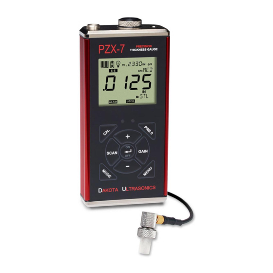
CHAPTER ONE INTRODUCTION The Dakota Ultrasonics model PZX-7 DL is a precision ultrasonic micrometer. Based on the same operating principles as SONAR, the PZX-7 DL is capable of measuring the thickness of various materials with accuracy as high as 0.0001 inches, or ... -
Page 6: Chapter Two Keypad, Menu, Display & Connectors
CHAPTER TWO KEYPAD, MENU, DISPLAY & CONNECTORS The Keypad 2.1 ON/OFF/ENTER Key The ON/OFF/ENTER key powers the unit ON or OFF. Since the same key is also used as an ENTER key, the gauge is powered off by pressing and holding down the key until the unit powers off. -
Page 7: Cal Key
PZX-7 DL Ultrasonic Thickness Gauge 2.3 CAL Key The CAL key is used to enter and exit the PZX-7 DL's calibration mode. This mode is used to adjust the sound velocity value that the PZX-7 DL will use when calculating thickness. -
Page 8: Menu Key
Dakota Ultrasonics 2.8 MENU Key The MENU key is used to access and set all of the additional features of the PZX-7 DL that are not at the top level of the keypad with a dedicated key. The features and... -
Page 9: The Display
PZX-7 DL Ultrasonic Thickness Gauge 6) Press the key to accept changes and return to the top level of features, or the key at any time to abort changes and return the measurement screen. 2.9 The Display The PZX-7 DL uses a custom glass LCD backlit low temperature display for use in a variety of climate conditions. - Page 10 Dakota Ultrasonics F. Backlight : When this icon is illuminated, it indicates the backlight is on. G. Small 7 Segment: The material velocity, speed the sound wave travels through a given medium/material, is displayed in this area, informing the user what material the PZX-7 DL is currently calibrated too.
-
Page 11: The Transducer
PZX-7 DL Ultrasonic Thickness Gauge 2.10 The Transducer Delay Line Contact The Transducer is the “business end” of the PZX-7 DL. It transmits and receives ultrasonic sound waves that the PZX-7 DL uses to calculate the thickness of the material being measured. The transducer connects to the PZX-7 DL using a single shielded coaxial cable with microdot connectors. - Page 12 Dakota Ultrasonics The Delay line is fastened to the transducer with a retaining ring. A drop of couplant is applied between the delay line and transducer body. Refer to the diagram above. The couplant should be checked on a regular basis to keep it from drying out. To replenish, unscrew the retaining ring counterclockwise, separate the delay line from the body, ‘clean both surfaces’, apply a drop of couplant, and reassemble.
-
Page 13: Top & Bottom End Caps
PZX-7 DL Ultrasonic Thickness Gauge 2.11 Top & Bottom End Caps The top & bottom end panels are where all connections are made to the PZX-7 DL. The diagram above shows the layout and description of the connectors: Transducer Connector Refer to Diagram: The transducer connector and battery cover/probe zero disk are located on the PZX-7 DL’s top end cap. -
Page 14: Chapter Three Principals Of Ultrasonic Measurement
CHAPTER THREE PRINCIPALS OF ULTRASONIC MEASUREMENT 3.1 Time versus thickness relationship Ultrasonic thickness measurements depend on measuring the length of time it takes for sound to travel through the material being tested. The ratio of the thickness versus the time is known as the sound velocity. In order to make accurate measurements, a sound velocity must be determined and entered into the instrument. -
Page 15: Temperature
PZX-7 DL Ultrasonic Thickness Gauge 3.5 Temperature Temperature has an effect on sound velocity. The higher the temperature, the slower sound travels in a material. High temperatures can also damage transducers and present a problem for various liquid couplants. Since the sound velocity varies with temperature it is important to calibrate at the same temperature as the material being measured. - Page 16 Dakota Ultrasonics that two return echoes are required to effectively measure the test material. As a result, the type and thickness of the coating will affect the ability to achieve a successful measurement. Both delay line and contact style transducers can be used for through paint/coating measurements.
-
Page 17: Chapter Four Selecting The Measurement Mode
CHAPTER FOUR SELECTING THE MEASUREMENT MODE 4.1 Which mode & transducer do I use for my application? High penetration plastics and castings The most common mode for these types of applications is pulse-echo. Thicker cast iron and plastics applications will generally require lower frequencies depending on the material type and thickness. - Page 18 Dakota Ultrasonics transducer in either echo-echo or interface-echo modes. If using a contact style transducer, a high frequency option should be considered. Restricted access Measuring materials with extreme curvatures or restricted access are best suited for higher frequencies and smaller diameter transducers or tip options.
-
Page 19: Chapter Five Making Measurements
CHAPTER FIVE MAKING MEASUREMENTS The steps involved in making measurements are detailed in this section. The following sections outline how to setup and prepare your PZX-7 DL for field use. In pulse-echo mode the probe zero must be performed on the reference disk (battery disk) attached to the top of the instrument. -
Page 20: Material Calibration
Dakota Ultrasonics 1) Apply a drop of couplant on the transducer and place the transducer in steady contact with the disk (battery cover) located at the top of the unit to obtain a measurement. 2) Be sure all six repeatability/stability bars in the top left corner of the display are fully illuminated and stable, and last digit of the measurement is toggling only +/- .001”... - Page 21 PZX-7 DL Ultrasonic Thickness Gauge 1) With the transducer free from contact with the material, press the to display the current velocity. 2) Use the keys to scroll the velocity to the known target value. Note: The longer the keys are pressed and held, the faster the value will increment/decrement.
- Page 22 Dakota Ultrasonics Note: Be sure that a probe zero has been performed prior to performing this calibration procedure. 1) Physically measure an exact sample of the material, or a location directly on the material to be measured, using a set of calipers or a digital micrometer.
- Page 23 PZX-7 DL Ultrasonic Thickness Gauge Note: CHECK YOUR CALIBRATION! Place the transducer back on the calibration point and verify the thickness. If the thickness is not correct, repeat the steps above. Two Known Thicknesses The two point calibration should be considered when an application requires improved accuracy over a small measurement range based on tolerance requirements.
- Page 24 Dakota Ultrasonics 2) Apply a drop of couplant on the transducer and place the transducer in steady contact with either the minimum or maximum sample or actual test material. Be sure that the reading is stable and the repeatability indicator in the top left corner of the display is fully lit and stable.
- Page 25 PZX-7 DL Ultrasonic Thickness Gauge 8) Press the key to set the calculated material velocity and return to the measurement screen. Note: CHECK YOUR CALIBRATION! Place the transducer back on the calibration points. The thickness readings should now match the known thickness values with minimal error.
- Page 26 Dakota Ultrasonics 4) Use the keys to scroll through the material options. in/µs ALUMINUM 0.250 6350 (2024) 0.233 5918 STEEL (4340) 0.223 5664 STAINLESS (303) 0.180 4572 CAST IRON 0.106 2692 PLEXIGLASS 0.094 2388 0.092 2337 POLYSTYRENE 0.070 1778 POLYURETHANE...
- Page 27 PZX-7 DL Ultrasonic Thickness Gauge 9) Note: Pressing the key prior to pressing the key will abort to the measurement screen without saving any changes.
-
Page 28: Chapter Six Through Paint Measurement
CHAPTER SIX THROUGH PAINT MEASUREMENT 6.1 Introduction Through paint measurement is accomplished by measuring the time between two repeat echoes from the back surface of the material. Since both of these back wall echoes travel the same path through the paint or coating, the thickness of the coating is subtracted out of the measurement so that only the actual material thickness is measured. - Page 29 PZX-7 DL Ultrasonic Thickness Gauge 1) Press the key to toggle between the measurement modes, for a given transducer type (contact or delay line), to echo-echo (E-E) mode. Note: An icon will be illuminated in the top left portion of the display to indicate PZX-7 DL the measurement mode the is currently using.
-
Page 30: Chapter Seven Velocity Gauge
CHAPTER SEVEN VELOCITY GAUGE 7.1 Velocity Gauge (VX) The PZX-7 DL includes a function to convert the unit into a dedicated velocity gauge. With this feature enabled, the PZX-7 DL will display all measurements in terms of velocity, inches per microsecond (IN /s) or meters per second (M /s), rather than dimensional inches or millimeters. -
Page 31: Calibration To A Known Thickness
PZX-7 DL Ultrasonic Thickness Gauge 5) When the desired VX setting is displayed, press the key to set the status and return to the measurement screen. 7.2 Calibration to a known thickness In order to calibrate the PZX-7 DL a ‘known thickness’ on the material or part will be used. -
Page 32: Calibration To A Known Velocity
Dakota Ultrasonics 5) Use the keys to scroll to the known thickness value. Note: The longer the keys are pressed and held, the faster the value will increment/decrement. Note: Pressing the key prior to pressing the key will abort the cal routine without saving any changes. - Page 33 PZX-7 DL Ultrasonic Thickness Gauge 1) Apply a drop of couplant on the transducer and place the transducer in steady contact with the sample or actual test material. Be sure that the velocity measurement is stable and the repeatability indicator, in the top left corner of the display, is fully lit and stable.
-
Page 34: Chapter Eight Additional Features
CHAPTER EIGHT ADDITIONAL FEATURES 8.1 Gain The gain, or amplification of the return echoes, can be adjusted in the PZX-7 DL to accommodate a variety of materials and applications. The setting of the gain is crucial in order to obtain valid readings during the measurement process. Too much gain may result in erroneous measurements, detecting on noise rather than the actual material back wall surface. -
Page 35: High Speed Scan
PZX-7 DL Ultrasonic Thickness Gauge 1) Press the key to access the menu items/features. 2) Use the keys to scroll through the items/features until the GAIN feature is being displayed. 3) Press the key to edit the gain setting. The edit icon will be illuminated and flashing. -
Page 36: Alarm
Dakota Ultrasonics 1) Press the key to access the menu items/features. 2) Use the keys to scroll through the items/features until the SCAN feature is being displayed. 3) Press the key to edit the scan setting. The edit icon will be illuminated and flashing. -
Page 37: Differential
PZX-7 DL Ultrasonic Thickness Gauge 2) Use the keys to scroll through the items/features until the ALRM feature is being displayed. 3) Press the key to edit the alarm status. The edit icon will be illuminated and flashing. 4) Use the keys to toggle alarm on/off/beep. -
Page 38: Units
Dakota Ultrasonics The steps below outline how to enable and enter the nominal value to use this feature: Differential 1) Press the key to access the menu items/features. 2) Use the keys to scroll through the items/features until the DIFF feature is being displayed. -
Page 39: Lite
PZX-7 DL Ultrasonic Thickness Gauge The procedure to select the units is outlined as below: Units 1) Press the key to access the menu items/features. 2) Use the keys to scroll through the items/features until the UNIT feature is being displayed. 3) Press the key to edit the units setting. - Page 40 Dakota Ultrasonics setting only lights the display when the gauge is coupled to the material and receiving a measurement. The steps below outline how to toggle the options: Backlight 1) Press the key to access the menu items/features. 2) Use the keys to scroll through the items/features until the LITE feature is being displayed.
-
Page 41: Beep
PZX-7 DL Ultrasonic Thickness Gauge 8.7 Beep The PZX-7 DL also has a feature to use the internal beeper, most commonly used with the alarm feature, for the key strokes on the keypad. When enabled, pressing any of the keys on the keypad will sound the beeper. The procedure to enable the keyboard beeper feature is outlined below: Beeper 1) Press the... - Page 42 Dakota Ultrasonics The procedure to select the probe type is outlined below: Probe 1) Press the key to access the menu items/features. 2) Use the keys to scroll through the items/features until the PROB feature is being displayed. 3) Press the key to edit the probe type.
-
Page 43: Velocity (Vx)
PZX-7 DL Ultrasonic Thickness Gauge 7) When the desired PROB diameter is displayed, press the key to set the diameter and return to the measurement screen. 8.9 Velocity (VX) When the velocity setting (VX) is enabled, the PZX-7 DL will display the material velocity as the primary measurement quantity instead of dimensional thickness. -
Page 44: Lock
Dakota Ultrasonics Note: Pressing the key prior to pressing the key will abort to the measurement screen without saving changes. 5) When the desired VX setting is displayed, press the key to set the status and return to the measurement screen. - Page 45 PZX-7 DL Ultrasonic Thickness Gauge The procedure to reset the gauge is outlined below: Factory Reset 1) With the PZX-7 DL powered off, press and hold down the keys while powering the PZX-7 DL on Note: Once the measurement screen is displayed the can be released.
-
Page 46: Chapter Nine Data Storage
CHAPTER NINE DATA STORAGE 9.1 Introduction The PZX-7 DL is equipped with a basic and convenient sequential style data logger that’s intuitive to operate. By ‘sequential’ meaning a single column of 250 measurements and a total of 40 individual files, for a total storage capacity of 10,000 measurements. -
Page 47: Storing A Measurement
PZX-7 DL Ultrasonic Thickness Gauge 4) When the desired FILE is displayed, press the key to open the file and return to the measurement screen. Note: The FILE and LOC (location) will be displayed in lower left portion of the measurement screen. -
Page 48: Clearing A File
Dakota Ultrasonics (memory) in the top right corner of the display. If the key is pressed to store another measurement at that location, FULL will briefly be displayed on the screen indicating a measurement has already been stored at that location. Pressing the key will clear the previously stored measurement from the location. -
Page 49: Clear All Files
PZX-7 DL Ultrasonic Thickness Gauge 6) Press the key to display the confirmation screen. CLR? will be displayed, as well as a flashing Yes/No option. 7) Press the key for YES, and the key for NO. The edit icon will be illuminated and flashing. Note: Pressing the key prior to pressing the key will abort to the... - Page 50 Dakota Ultrasonics 3) Press the key to display the confirmation screen. CLR ALL is displayed, as well as a flashing Yes/No option. 4) Press the key for YES, and the key for NO. The edit icon will be illuminated and flashing.
-
Page 51: Chapter Ten Data Transfer & Power Options
CHAPTER TEN DATA TRANSFER & POWER OPTIONS 10.1 Connectivity The PZX-7 DL is connected to a PC with a USB-C to USB Type A cable, supplied with the kit (part# N-003-0330). The gauge has a file system and the PC will recognize it as an external hard disk, or thumb drive. -
Page 52: Line Power
Dakota Ultrasonics Now that the files have been located and are accessible, they can either be opened from the PZX-7 DL’s memory, or copied to another location/folder on your PC. To accomplish this, simply ‘drag and drop’ files in a new folder on your PC, or on your desktop. -
Page 53: Appendix A - Velocity Table
APPENDIX A - VELOCITY TABLE Material sound velocity sound velocity in/us Aluminum 0.2510 6375 Beryllium 0.5080 12903 Brass 0.1730 4394 Bronze 0.1390 3531 Cadmium 0.1090 2769 Columbium 0.1940 4928 Copper 0.1830 4648 Glass (plate) 0.2270 5766 Glycerine 0.0760 1930 Gold 0.1280 3251 Inconel... - Page 54 Dakota Ultrasonics 0.1310 3327 Titanium 0.2400 6096 Tungsten 0.2040 5182 Uranium 0.1330 3378 Water 0.0580 1473 Zinc 0.1660 4216 Zirconium 0.1830 4648...
-
Page 55: Appendix B- Application Notes
APPENDIX B- APPLICATION NOTES Measuring hot surfaces The velocity of sound through a substance is dependent on its temperature. As materials heat up, the velocity of sound through them decreases. In most applications with surface temperatures less than about 200F (100C), no special procedures must be observed. - Page 56 Dakota Ultrasonics An additional important consideration when measuring laminates is that many included air gaps or pockets which will cause an early reflection of the ultrasound beam. This effect will be noticed as a sudden decrease in thickness in an otherwise regular surface.
- Page 57 Additionally, Dakota Ultrasonics warrants transducers and accessories against such defects for a period of 90 days from receipt by the end user. If Dakota Ultrasonics receives notice of such defects during the warranty period, Dakota Ultrasonics will either, at its option, repair or replace products that prove to be defective.
Need help?
Do you have a question about the PZX-7DL and is the answer not in the manual?
Questions and answers