Table of Contents
Advertisement
Quick Links
Download this manual
See also:
Operating Manual
Advertisement
Table of Contents

Subscribe to Our Youtube Channel
Related Manuals for DAKOTA ULTRASONICS MMX-7


Summary of Contents for DAKOTA ULTRASONICS MMX-7
- Page 1 OPERATION MANUAL DAKOTA ULTRASONICS Data Logging Thickness Gauge P/N P-160-0002 Rev 1.10, January 2008...
-
Page 3: Table Of Contents
CHAPTER SEVEN USING THE DIGITS & B-SCAN DISPLAYS ......41 CHAPTER EIGHT THRU PAINT MEASUREMENT TECHNIQUE ....53 CHAPTER NINE ADDITIONAL FEATURES OF THE MMX-7......54 CHAPTER TEN DATA STORAGE – SETUP, EDIT, & VIEW GRIDS ....58 CHAPTER ELEVEN SETUPS – CREATE, STORE, EDIT, & RECALL ....75 CHAPTER TWELVE USING THE UTILITY SOFTWARE........81... -
Page 5: Chapter One Introduction
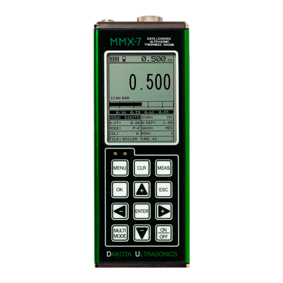
CHAPTER ONE INTRODUCTION The Dakota Ultrasonics model MMX-7 is a digital ultrasonic thickness gauge with a time based B-Scan and alpha numeric data logger. Based on the same operating principles as SONAR, the MMX-7 is capable of measuring the thickness of various materials with accuracy as high as ±... -
Page 6: Chapter Two Quick Startup Guide
CHAPTER TWO QUICK STARTUP GUIDE Turn the MMX-7 on and off using the switch located on the bottom right corner of the keypad. When MMX-7 is initially turned on, a flash logo and blinking lights will be displayed prior to entering into the main measurement screen. Note: This section is primarily written as a basic startup guide only. - Page 7 ESC to cancel the selecting the transducer. 2.2 Probe Zero & Calibration The next step is to calibrate the MMX-7 to the material and transducer being used. If the materials sound velocity is unknown, the MMX-7 can be calibrated to a known thickness sample.
- Page 8 If the material velocity is known, the user may wish to simply enter the velocity number into the MMX-7, rather than have the MMX-7 calculate the velocity value on using a know thickness. The steps for entering the velocity are outlined below: Using a Known Material Velocity 1) Press the MENU key once to activate the menu items tab.
- Page 9 MMX-7 Data Logging Ultrasonic Thickness Gauge 2) Use the UP and DOWN arrow keys to scroll through the sub menu items until VELOCITY is highlighted. 3) Press the ENTER key to display the Digits Edit Box. 4) Press the UP and DOWN arrow keys to scroll the highlighted value.
- Page 10 Sometimes the sound velocity of a material is unknown. In this case a sample with a known thickness can be used to determine the sound velocity. It would be very handy to carry a set of mechanical calipers to use in conjunction with the MMX-7 for calibration in the field:...
- Page 11 MMX-7 Data Logging Ultrasonic Thickness Gauge 3) Use the UP and DOWN arrow keys to scroll through the sub menu items until ONE POINT is highlighted. 4) Press the ENTER key to display the Digits Edit Box. 5) Press the UP and DOWN arrow keys to scroll the highlighted value.
- Page 12 Dakota Ultrasonics Basic Material Type If the material velocity is unknown, and a sample thickness cannot be taken from the material, the user may opt to choose a basic material type from a list with approximate velocity numbers. It’s important to note that these velocities will not always be an exact representation of the material being tested.
- Page 13 MMX-7 Data Logging Ultrasonic Thickness Gauge 2.3 Measure The MMX-7 is now ready to measure. There are two different measurement view options, each with a specific purpose – Digits & B-Scan. The steps below outline how to toggle between the different view mode options: Selecting the Measurement View Option 1) Press the MENU key once to activate the menu items tab.
- Page 14 Dakota Ultrasonics been set to BSCAN. Use the following steps to adjust these settings directly from the measurement screen as follows: Adjusting the Start (B-ST) & Depth (B-DEP) Press the MEAS key once to activate the measure menu items. Press the MEAS key multiple times to move right and the ESC key multiple times to move left, until the either the B-ST or B-DEP cell is highlighted.
- Page 15 MMX-7 makes 4 measurements a second. In scan mode, the MMX-7 makes 32 measurements a second. When the MMX-7 is idle, only the left vertical bar and the underline will be displayed. However, when the MMX-7 is making a measurement, five or six of the bars should be displayed on the repeatability indicator.
-
Page 16: Chapter Three Keyboard, Menu, & Connector Reference
CHAPTER THREE KEYBOARD, MENU, & CONNECTOR REFERENCE 3.1 Menu Key (Operation & Sub Menus ) The Menu key activates the primary menu structure containing 9 menu tab groups. These tab groups then contain sub menu items, or functions. The sub menu items have been organized in tab groups according to how closely they are related to the individual tab group names. - Page 17 Zero: The MMX-7 is zeroed in much the same way that a mechanical micrometer is zeroed. If the MMX-7 is not zeroed correctly, all of the measurements made using the MMX-7 may be in error by some fixed value. Refer to the section on page 32, for an explanation of this important procedure.
- Page 18 Dakota Ultrasonics AGC: The MMX-7 is equipped with an automatic gain control when operating in echo-echo mode only. This is much like turning the volume up or down on a stereo receiver. However, the MMX-7 will automatically control how much the volume is turned up or down.
- Page 19 Refer to page 77 for further info. Default Setup: Loads a basic default setup. Use only as a last resort when the setups in the MMX-7 have been corrupted and a computer is not accessible. Refer to page 79 for further info.
- Page 20 3.8 XFER (transfer) – Menu Backup Setups: Enables the user the ability to backup the setups currently stored in the MMX-7 to a PC via RS232 port. Refer the help section of the MMX- 7sonicview software for a complete electronic manual.
- Page 21 3.10 MEAS (measurement mode) Key The MEAS key puts the MMX-7 into it’s primary mode of operation. In this mode, the user has a complete view of the LCD, as well as control of the Hot Menu Functions.
- Page 22 Dakota Ultrasonics 1) Use the UP, DOWN, LEFT, and RIGHT arrow keys to increase and decrease the values of the hot function fields. 2) Repeat step 1 until the desired value has been achieved. Alternatively , the B-ST and B-DEP hot function fields can be changed using the Digit Edit Box as follows: 1) Press the ENTER key to display the Digits Edit Box.
- Page 23 3.15 MULTI MODE Key The MULTI MODE key toggles the measurement mode of the MMX-7, from pulse- echo (flaw mode), to echo -echo (thru paint) mode. This is a quick automatic preset mode that enables the user to change modes without having to manually adjust the mode between pulse-echo and echo-echo.
- Page 24 Lemo connector. It is designed to connect directly from the MMX-7 to a standard AT serial port on a PC. The cable supplied with the MMX-7 is a Lemo to 9 pin serial cable. Note: This connector is also used to upgrade the MMX-7 with the...
-
Page 25: Chapter Four Principals Of Ultrasonic Measurement
CHAPTER FOUR PRINCIPALS OF ULTRASONIC MEASUREMENT 4.1 Time versus thickness relationship Ultrasonic thickness measurements depend on measuring the length of time it takes for sound to travel through the material being tested. The ratio of the thickness versus the time is known as the sound velocity. In order to make accurate measurements, a sound velocity must be determined and entered into the instrument. - Page 26 Pulse-echo mode measures from the initial pulse (sometimes referred to as an artificial zero) to the first echo (reflection). In this mode, the transducer is placed on a reference disk, located on top of the MMX-7, and a key is pressed to establish a zero point for the particular transducer.
- Page 27 MMX-7 Data Logging Ultrasonic Thickness Gauge packaged in a single housing but acoustically isolated from each other with a sound barrier. This allows the transducer the ability to achieve very high sensitivity for detecting small defects. Also, the surface of the test material does not have to be as flat in order to obtain good measurements.
- Page 28 The repetition rate is how often the MMX-7 generates a burst of ultrasound. The MMX-7 has a fixed repetition rate of 1 kHz, or 1000 times per second. The MMX-7 updates the display 4 times per second in regular measurement mode and 32 times a second in hi speed scan mode.
-
Page 29: Chapter Five Selecting The Measurement Mode
SELECTING THE MEASUREMENT MODE 5.1 The setup library The MMX-7 contains 64 user configurable preset locations to store custom setups for easy recall. These setups can be optimi zed for the user’s specific application needs and can also be stored on a PC and transferred bi-directionally using Dakota’s PC interface software included with the instrument. - Page 30 Dakota Ultrasonics Thru coating measurements require special high damped transducers. The most common transducers are the 3.5, 5, and 7.5MHz hi damped transducers. These transducers are suitable for use in both pulse-echo and echo-echo modes. This conveniently enables the user to accurately measure overall material thickness using the thru Coating mode, and then conveniently switch to pit detection mode without changing transducers.
- Page 31 MMX-7 Data Logging Ultrasonic Thickness Gauge 5.3 Factory Setup Chart Name Comment 1 Gn/AGC Velocity STEEL BASIC 0.2330 in/uSec STEEL THRU PNT STD ¼ 5MHZ HD 0.2330 in/uSec STEEL THRU PNT EXT ½ 3MHZ HD 0.2330 in/uSec ALUMINUM W/GATE ¼” 7.5MHZ 0.2510 in/uSec...
-
Page 32: Chapter Six Making Measurements
In this case the reference disk mounted to the MMX-7 is not used. This is called two- point calibration and is described on page 37. - Page 33 6) Press the OK key to select the transducer and return to the menu screen, or ESC to cancel the material selection. Now that the proper transducer has been selected and connected to the MMX-7, the measurement mode must be chosen according to the type of application. Following...
- Page 34 Dakota Ultrasonics Selected from a Setup Important Note: Stored setups will save all the parameters of the MMX-7. Therefore, if a transducer was selected in the previous section and a setup is now being recalled, the transducer saved in the setup will overwrite the transducer previously selected.
- Page 35 MMX-7 Data Logging Ultrasonic Thickness Gauge 6) Press the OK key to select the setup and return to the menu screen, or ESC to cancel the selection process. Press the MEAS key to return to the measurement screen. Alternatively, the measurement mode can be simply selected from the Hot Menu...
- Page 36 If the MMX-7 is not zeroed correctly, all of the measurements taken, may be in error by some fixed value. In order to perform a probe zero, the MMX-7 must be in pulse- echo mode. If echo-echo mode was previously selected in the last section, skip this section and continue on to the next.
- Page 37 8) Press the MEAS key to return to the measurement screen. 6.3 Material Calibration In order for the MMX-7 to make accurate measurements, it must be set to the correct sound velocity of the material being measured. Different types of materials have different inherent sound velocities.
- Page 38 - optimizing linearity over large ranges. The Two Point calibration allows for greater accuracy over small ranges by calculating the probe zero and velocity. The MMX-7 provides four simple methods for setting the sound-velocity outlined below: Calibration to a known velocity 1) Press the MENU key once to activate the menu items tab.
- Page 39 MMX-7 Data Logging Ultrasonic Thickness Gauge Finally, press the MEAS key to return to the measurement screen and begin taking readings.
- Page 40 Note: It’s always best to calibrate on the thickest location on the sample, rather than on the thinnest location, as the percentage error is much less with respect to the MMX-7’s resolution of +/- .001” (0.01mm).
- Page 41 MMX-7 Data Logging Ultrasonic Thickness Gauge 4) Press the ENTER key to display the Digits Edit Box. 5) Press the UP and DOWN arrow keys to scroll the highlighted value. 6) Press the LEFT and RIGHT arrow keys to scroll the digit locations.
- Page 42 Dakota Ultrasonics 1) Using a set of calipers, physically measure two known thickness locations on the sample of material. Note: The two locations should represent the desired thickness range being measured. If the range is from .250” - 1.000”, then the two known locations should represent this range, or be slightly outside or inside of this range.
- Page 43 MMX-7 Data Logging Ultrasonic Thickness Gauge second known thickness location. Be sure that the reading is stable and the repeatability indicator, located in the top left corner of the display, is fully lit and stable. 10) Use the UP and DOWN arrow keys to highlight the TWO POINT calibration submenu item.
- Page 44 Dakota Ultrasonics Built in Material Selection 1) Press the MENU key once to activate the menu items tab. Press the MENU key multiple times to tab right, and the ESC key multiple times to tab left, until the CAL menu is highlighted and displaying the submenu items.
-
Page 45: Chapter Seven Using The Digits & B-Scan Displays
We’ll take a better look at these options in this chapter. Note: In order to recall and use the new adjustments made to the MMX-7 at a later time, the user must save the modified settings in one of the setup locations prior to powering off the unit. Refer page 75 for more information on setups. - Page 46 Dakota Ultrasonics 2) Use the UP and DOWN arrow keys to scroll through the sub menu items until VIEW is highlighted. 3) Use the LEFT and RIGHT arrow keys to scroll the view options. Once the appropriate view is displayed, press the MEAS key to return to the measurement screen.
- Page 47 MMX-7 Data Logging Ultrasonic Thickness Gauge signal. If the MMX-7 is displaying a reading from memory, the repeatability indicator will be replaced by the text “MEM”. B) Battery life indicator – Fully charged batteries will appear filled in solid. Note: The diagram shows the batteries at approximately 50%.
- Page 48 A) Stability of Reading Indicator – Indicates the stability of the echo signal on a scale of 1 to 6 – the solid bars displayed in the figure above indicate a repeatable signal. If the MMX-7 is displaying a reading from memory, the repeatability indicator will be replaced by the text “MEM”.
- Page 49 7.3 Adjusting the B-Scan Start (B-ST) & Depth (B-DEP) In order to use the B-Scan and Scan Bar features of the MMX-7 effectively, the starting depth and overall depth must be setup correctly. This can be adjusted using the B-ST (start) and the B-DEP (depth) features of the MMX-7.
- Page 50 Dakota Ultrasonics Overall range (B-DEP) Once again, just to reiterate, B-DEP is the overall viewable thickness range being tested. This should be set to a value slightly larger then the expected maximum range being measured. The procedures to adjust the overall thickness range viewed...
- Page 51 MMX-7 Data Logging Ultrasonic Thickness Gauge The user can also access and adjust the B-DEP range from the tabbed menus. However, this method is a more tedious than making the adjustments using the Hot Menus. The procedure using the tabbed menus is outlined below: Adjusting the Overall Depth (B-DEP) using the Tabbed Menus 1) Press the MENU key once to activate the menu items tab.
- Page 52 Dakota Ultrasonics 9) Finally, press the MEAS key to return to the measurement screen and begin taking readings. Starting depth (B-ST) The starting B-ST, or starting depth, is the starting thickness value. Often times this value will simply be set to zero in order to start measuring at 0.000”. The only time this value will be set to something other than zero, is if the user needs to zoom in even closer.
- Page 53 MMX-7 Data Logging Ultrasonic Thickness Gauge 2) Press the UP, DOWN, LEFT, and RIGHT arrow keys to scroll the highlighted value. 3) Alternatively , press the ENTER key to display the Digits Edit Box. 4) Press the UP and DOWN arrow keys to scroll the highlighted value.
- Page 54 7.4 Gain The gain, or amplification of the return echoes, can be adjusted in the MMX-7 to accommodate a variety of applications. The setti ng of the gain is crucial in order to obtain valid readings during the measurement process. Too much gain may result in erroneous measurements, by detecting on noise rather than the actual material back wall itself.
- Page 55 MMX-7 into a high gain setting. In any case, the selectable gain settings offer the user some additional options to resolve application issues.
- Page 56 Dakota Ultrasonics The user can also access and adjust the gain from the tabbed menus. However, this method is more tedious than making the adjustments using the Hot Menus. The procedure using the tabbed menus is outlined below: Adjusting the Gain using the Tabbed Menus 1) Press the MENU key once to activate the menu items tab.
-
Page 57: Chapter Eight Thru Paint Measurement Technique
The MMX-7 can also be configure for thru paint applications by selecting a factory setup stored in the list of setups in the MMX-7. Refer to page 75 for information on recalling a setup. Once either the transducer type or setup has been selected, the... -
Page 58: Chapter Nine Additional Features Of The Mmx-7
Press the MEAS key to return to the measurement screen. 9.2 Alarm Mode The Alarm Mode feature of the MMX-7 provides the user with a method of setting tolerances, or limits, for a particular application requirement. This feature may be used for a variety of applications to verify the material is within the manufacturer specifications. - Page 59 MMX-7 Data Logging Ultrasonic Thickness Gauge activate and utilize only one of the limit values, depending on their specific application requirements. The procedures to use the ALARM MODE feature are outlined below: UTIL MENU – ALARM MODE Toggle Alarm Status (on/off) 1) Press the MENU key once to activate the menu items tab.
- Page 60 Dakota Ultrasonics Use the LEFT and RIGHT arrow keys to toggle the ALARM STATUS on/off/audible. Continue on to the next section “Setting the Alarm Lo Limit”. Setting the Alarm LO Limit 1) Assuming the ALARM STATUS is ON, use the UP and DOWN arrow keys to scroll through the sub menu items until ALARM LO LIMIT is highlighted.
- Page 61 MMX-7 Data Logging Ultrasonic Thickness Gauge Setting the Alarm HI Limit 1) Assuming the ALARM STATUS is ON,use the UP and DOWN arrow keys to scroll through the sub menu items until ALARM HI LIMIT is highlighted. 2) Press the LEFT and RIGHT arrow keys to scroll the value. When the correct alarm value is being displayed, proceed to step 8 .
-
Page 62: Chapter Ten Data Storage - Setup, Edit, & View Grids
10.1 Introduction to Grid (spreadsheet) format Data is stored in the MMX-7 in a spreadsheet like format called a GRID. A GRID is simply a table of readings. The location in a grid is specified by giving a row and column coordinate. - Page 63 MMX-7 Data Logging Ultrasonic Thickness Gauge 1) Press the MENU key once to activate the menu items tab. Press the MENU key multiple times to tab right, and the ESC key multiple times to tab left, until the DATA menu is highlighted and displaying the submenu items.
- Page 64 Dakota Ultrasonics Creating a Grid Note 1) Use the UP and DOWN arrow keys to scroll through the new Grid List Items until NOTE is highlighted. 2) Press the ENTER key to activate the Alpha Edit Box. 3) Use the UP, DOWN, LEFT, & RIGHT arrow keys to highlight the appropriate alpha characters.
- Page 65 MMX-7 Data Logging Ultrasonic Thickness Gauge 5) Use the CLR key to backspace if necessary. 6) Repeat steps 3 through 5 until the Grid Note is completed. 7) Press the OK key to save the Grid Note and return to the Grid List Items menu, or ESC to cancel entering the Grid Note.
- Page 66 Dakota Ultrasonics 2) Press the ENTER key to activate the Coordinate Edit Box. 3) Use the LEFT, & RIGHT arrow keys to scroll the Columns, and the UP, DOWN arrow keys to scroll the Rows. 4) Press the OK key to select the coordinate and return to the Grid List Items screen, or ESC to cancel the selection and return to the Grid List Items menu.
- Page 67 “NOT ENOUGH MEMORY“ will be displayed. Press the OK or ESC key to return to the Grid List Items menu. It may be necessary to free some memory in the MMX-7 at this time. Refer to page 68 for more information on Deleting a Grid .
- Page 68 Dakota Ultrasonics Selecting the Auto Increment Direction The Auto Increment feature gives the user the ability to specify which direction to advance the cursor after storing a reading. 5) Use the UP and DOWN arrow keys to scroll through the new Grid List Items until INCR.
- Page 69 MMX-7 Data Logging Ultrasonic Thickness Gauge Saving a Grid Once all the parameters are set, the user has the option of saving or canceling the new grid. 1) Use the UP and DOWN arrow keys to scroll through the new Grid List Items until CREATE NEW GRID? is highlighted.
- Page 70 Dakota Ultrasonics 4) Press the MEAS key to return to the measurement screen and begin storing readings. 10.3 Storing a reading Now that a grid has been created, it’s time to make some measurements and store the readings. The following procedures outline this process: Storing a Reading 1) Press the MEAS key once to activate measure menu items.
- Page 71 10.4 Viewing stored readings It is sometimes necessary to go back and view the stored readings and waveforms using the MMX-7 without a PC. The following procedures outline this process: Viewing Stored Readings & B-Scans 1) Press the MEAS key once to activate measure menu items. Press the MEAS key multiple times to move right and the ESC key multiple times to move left until the COL or ROW cell is highlighted.
- Page 72 Dakota Ultrasonics 4) The user may opt to clear a specific reading and save a new one at any time. Press the CLR key in the appropriate cell location to clear the reading, take a new measurement, and press the OK key to save the new reading.
- Page 73 MMX-7 Data Logging Ultrasonic Thickness Gauge 3) Press the ENTER key to display the Grid List Box. 4) Use the UP and DOWN arrow keys to scroll through the stored Grids until the target File to delete is highlighted. 5) Press the OK key to delete the File.
- Page 74 Dakota Ultrasonics 3) Press the ENTER key to activate the confirmation screen. 4) Press the OK key to delete All Files from memory, or the ESC key to abort. 5) Press the MEAS key to return to the measurement screen.
- Page 75 MMX-7 Data Logging Ultrasonic Thickness Gauge 1) Press the MENU key once to activate the menu items tab. Press the MENU key multiple times to tab right and the ESC key multiple times to tab left until the DATA menu is highlighted and displaying the submenu items.
- Page 76 Dakota Ultrasonics 9) Repeat steps 6 - 8 until the Comments are completed. 10) Press the UP or DOWN arrow key to highlight SAVE CHANGES, and the OK key to activate the confirmation screen. 11) Press the OK to save the changes or the ESC key to cancel editing the grid parameters.
- Page 77 The user may have transferred grid templates from a PC to the MMX-7, or setup grids using the MMX-7 at an earlier time. The name of the currently active grid is always displayed at the bottom of the Hot Menu Items in measurement mode (refer to photo below).
- Page 78 Dakota Ultrasonics 5) Press the ENTER key to activate the confirmation screen. 6) Press the OK key to load the grid from memory. 7) Press the MEAS key to return to the measure screen.
-
Page 79: Chapter Eleven Setups - Create, Store, Edit, & Recall
11.2 Opening a Setup The MMX-7 is loaded with a number of setups from the factory. These setups can be opened, edited, and saved to any one of 64 setup locations. If a factory setup is written over, the user can simply reload the default factory setups at anytime using the utility software included with the MMX-7. - Page 80 Dakota Ultrasonics Opening a Setup 1) Press the MENU key once to activate the menu items tab. Press the MENU key multiple times to tab right and the ESC key multiple times to tab left until the SETUP menu is highlighted and displaying the submenu items.
- Page 81 7) Press the MEAS key to return to the measure screen. 11.3 Saving a Setup Once the MMX-7 parameters and features have be adjusted for an application, the user may elect to save these setting to a specific setup location for future use. This can potentially save time and reduce error between users.
- Page 82 Dakota Ultrasonics 2) Use the UP and DOWN arrow keys to scroll through the sub menu items until SAVE is highlighted. Press the ENTER key to display the Save Setup Parameters List Box. Press the UP and DOWN arrow keys to scroll the Name and Note parameters.
- Page 83 Save Setup function can also be considered an Edit Function. 11.4 Using the Default Setup The default setup feature was added to the MMX-7 to use, as a last resort, if there are no setups stored in the gauge –factory or otherwise. The only time this might...
- Page 84 Dakota Ultrasonics 1) Press the MENU key once to activate the menu items tab. Press the MENU key multiple times to tab right and the ESC key multiple times to tab left until the SETUP menu is highlighted and displaying the submenu items.
-
Page 85: Chapter Twelve Using The Utility Software
MvxPvxView. MvxPvxView requires an available communications port in order to transfer data to and from the MMX-7. MvxPvxView supports COM1, COM2, COM3, and COM4. USB to Serial Converter Some newer laptop computers do not have standard serial ports. In this case it is possible to use a USB to Serial converter. -
Page 86: Appendix A - Velocity Table
APPENDIX A - VELOCITY TABLE Material sound velocity sound velocity in/us Aluminum 0.2510 6375 Beryllium 0.5080 12903 Brass 0.1730 4394 Bronze 0.1390 3531 Cadmium 0.1090 2769 Columbium 0.1940 4928 Copper 0.1830 4648 Glass (plate) 0.2270 5766 Glycerine 0.0760 1930 Gold 0.1280 3251 Inconel... - Page 87 MMX-7 Data Logging Ultrasonic Thickness Gauge 0.1310 3327 Titanium 0.2400 6096 Tungsten 0.2040 5182 Uranium 0.1330 3378 Water 0.0580 1473 Zinc 0.1660 4216 Zirconium 0.1830 4648...
-
Page 88: Appendix B - Setup Library
APPENDIX A - SETUP LIBRARY Name Comment 1 Gn/AGC Velocity STEEL BASIC 0.2330 in/uSec STEEL THRU PNT STD ¼ 5MHZ HD 0.2330 in/uSec STEEL THRU PNT EXT ½ 3MHZ HD 0.2330 in/uSec ALUMINUM W/GATE ¼” 7.5MHZ 0.2510 in/uSec PLASTIC W/GATE THK ½... - Page 89 MATERIAL SAFETY DATA SHEET N/A = not applicable or not available (To comply with 29 CFR 1910.1200) Effective Date: 2/1/04 SECTION 1 – PRODUCT IDENTIFICATION NFPA Hazardous Materials Product Name: SOUNDSAFE® Identification System (est) Generic Name: Ultrasonic Couplant Health……………………0 Manufacturer: Sonotech, Inc. Flammability…………….0 774 Marine Dr., Bellingham, WA 98225 Reactivity………………..0...
Need help?
Do you have a question about the MMX-7 and is the answer not in the manual?
Questions and answers