
Related Manuals for DAKOTA ULTRASONICS PZX-7


Summary of Contents for DAKOTA ULTRASONICS PZX-7
- Page 1 OPERATION MANUAL DAKOTA ULTRASONICS Precision Ultrasonic Thickness Gauge P/N P-307-0002 Rev 1.00, January 2019...
-
Page 3: Table Of Contents
CONTENTS CHAPTER ONE INTRODUCTION ..............1 1.1 D ......................... 1 ISCLAIMER CHAPTER TWO KEYPAD, MENU, DISPLAY & CONNECTORS ..... 2 2.1 ON/OFF/ENTER K … ..................... 2 2.2 PRB 0 K … ........................2 2.3 CAL K ….......................... 3 2.4 GAIN K …. - Page 4 7.3 C .................. 27 ALIBRATION TO A KNOWN VELOCITY CHAPTER EIGHT ADDITIONAL FEATURES ..........29 8.1 G ..........................29 8.2 H ......................30 PEED 8.3 A ..........................31 LARM 8.4 D ........................32 IFFERENTIAL 8.5 U ..........................33 NITS 8.6 L ...........................
-
Page 5: Chapter One Introduction
1.1 Disclaimer While the PZX-7 is a basic digital instrument, it is equipped with a number of measurement modes and transducer options for additional versatility. It is strongly recommended that the contents of this manual be read in its entirety to avoid erroneous measurements based on operator error. -
Page 6: Chapter Two Keypad, Menu, Display & Connectors
2.2 PRB 0 Key The PRB 0 key is used to “zero” the PZX-7 in much the same way that a mechanical micrometer is zeroed. If the gauge is not zeroed correctly, all of the measurements that the gauge makes may be in error by some fixed value. -
Page 7: Cal Key
PZX-7 Ultrasonic Multi-Mode Thickness Gauge 2.3 CAL Key The CAL key is used to enter and exit the PZX-7's calibration mode. This mode is used to adjust the sound velocity value that the PZX-7 will use when calculating thickness. The tool will either calculate the sound-velocity from a sample of the material being measured, or allow a known velocity value to be entered directly. -
Page 8: Menu Key
2.8 MENU Key The MENU key is used to access and set all of the additional features of the PZX-7 that are not at the top level of the keypad with a dedicated key. The features and setting are outlined in the table below:... -
Page 9: The Display
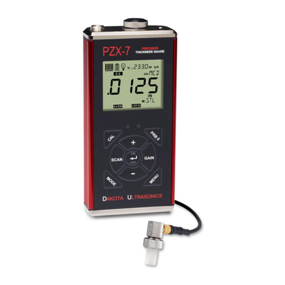
2.9 The Display The PZX-7 uses a custom glass LCD backlit low temperature display for use in a variety of climate conditions. It contains graphic icons, as well as both 7 and 14 segment display areas. Let’s take a closer look and what all these things are telling A. - Page 10 For a complete list of the menu features in the PZX-7, Refer to page 4 for a list. The PZX-7 can be locked once calibrated, to avoid accidently changing the calibration. When this icon is illuminated, the PZX-7 is in lock mode.
- Page 11 Contact The Transducer is the “business end” of the PZX-7. It transmits and receives ultrasonic sound waves that the PZX-7 uses to calculate the thickness of the material being measured. The transducer connects to the PZX-7 using a single shielded coaxial cable with microdot connectors.
-
Page 12: Top & Bottom End Caps
Contact Transducer The single element contact style transducers are commonly used for materials with an approximate range of 0.040” to the maximum range of the PZX-7 rated in steel and depending on the transducers diameter and frequency. The frequency range is 5.0 to 10 MHz, with diameters available at 0.125, 0.250, 0.375 and 0.500 inches. - Page 13 C female connector. It is designed to connect directly from the PZX-7 to a standard USB type A port on a PC. The cable supplied with the PZX-7 is a USB type C to a USB type A (pt# N-003-0330). See page 40 for information on connectivity.
-
Page 14: Chapter Three Principals Of Ultrasonic Measurement
CHAPTER THREE PRINCIPALS OF ULTRASONIC MEASUREMENT 3.1 Time versus thickness relationship Ultrasonic thickness measurements depend on measuring the length of time it takes for sound to travel through the material being tested. The ratio of the thickness versus the time is known as the sound velocity. In order to make accurate measurements, a sound velocity must be determined and entered into the instrument. -
Page 15: Temperature
(battery cover) will need to be performed prior to calibrating the PZX-7. The transducer is placed on the reference disk located on top of the PZX-7, and the PRB 0 key pressed to establish a zero point for the transducer connected. - Page 16 Dakota Ultrasonics that two return echoes are required to effectively measure the test material. As a result, the type and thickness of the coating will affect the ability to achieve a successful measurement. Both delay line and contact style transducers can be used for through paint/coating measurements.
-
Page 17: Chapter Four Selecting The Measurement Mode
CHAPTER FOUR SELECTING THE MEASUREMENT MODE 4.1 Which mode & transducer do I use for my application? High penetration plastics and castings The most common mode for these types of applications is pulse-echo. Thicker cast iron and plastics applications will generally require lower frequencies depending on the material type and thickness. - Page 18 Dakota Ultrasonics transducer in either echo-echo or interface-echo modes. If using a contact style transducer, a high frequency option should be considered. Restricted access Measuring materials with extreme curvatures or restricted access are best suited for higher frequencies and smaller diameter transducers or tip options.
-
Page 19: Chapter Five Making Measurements
If the PZX-7 is not zeroed correctly, all measurements will be in error by some fixed value. In order to perform a probe zero, you must be in pulse- echo mode. -
Page 20: Material Calibration
5.2 Material Calibration In order for the PZX-7 to make accurate measurements, it must be set to the correct sound velocity of the material being measured. Different types of materials have different inherent sound velocities. - Page 21 .100” (2.54mm) to 1.0” (25.4mm), the user should calibrate on a known thickness sample close to 1.0” (25.4mm). Note: It’s always handy to carry a set of mechanical calipers to use in conjunction with the PZX-7 for calibration of various materials in the field:...
- Page 22 Dakota Ultrasonics Note: Be sure that a probe zero has been performed prior to performing this calibration procedure. 1) Physically measure an exact sample of the material, or a location directly on the material to be measured, using a set of calipers or a digital micrometer.
- Page 23 .250” (6.35mm) and a two point calibration at .080” (2.03mm), or something close to the min/max values of the measurement range. Note: The PZX-7 also offers the capability of setting the ‘probe zero’ to use any reference standard as the ‘probe zero’ standard. For clarification, if it’s desired to use a one inch reference of a specific material type as the ‘zero’...
- Page 24 “1 of 2”, which sets the zero value and returns to the measurement screen. Note: The internal zero of the PZX-7 is now set. The procedure above can be used to set the internal zero of the PZX-7 to use any reference standard as the ‘probe zero’...
- Page 25 (MATL) list in the PZX-7 would offer a reasonable approximation of the thickness. There are 9 common materials and 2 user programmable settings available.
- Page 26 Dakota Ultrasonics in/µs ALUMINUM 0.250 6350 (2024) 0.233 5918 STEEL (4340) 0.223 5664 STAINLESS (303) 0.180 4572 CAST IRON 0.106 2692 PLEXIGLASS 0.094 2388 0.092 2337 POLYSTYRENE 0.070 1778 POLYURETHANE USER PROGRAMMABLE 5) When the desired MATL setting is displayed, press the key to set the material velocity and return to the measurement screen.
-
Page 27: Chapter Six Through Paint Measurement - Multimode
Since the PZX-7 is a basic easy to operate gauge without the adjustability you’d get using an advanced A-Scan scope, echo-echo mode is subject to limitations depending on type and thickness of the coating, as well as the type of transducer used. - Page 28 Dakota Ultrasonics 1) Press the key to toggle between the measurement modes, for a given transducer type (contact or delay line), to echo-echo (E-E) mode. Note: An icon will be illuminated in the top left portion of the display to indicate...
-
Page 29: Chapter Seven Velocity Gauge
VELOCITY GAUGE 7.1 Velocity Gauge (VX) The PZX-7 includes a function to convert the unit into a dedicated velocity gauge. With this feature enabled, the PZX-7 will display all measurements in terms of velocity, inches per microsecond (IN /s) or meters per second (M /s), rather than dimensional inches or millimeters. -
Page 30: Calibration To A Known Thickness
7.2 Calibration to a known thickness In order to calibrate the PZX-7 a ‘known thickness’ on the material or part will be used. The same location will be used for all the other parts in the group/batch to determine the velocity. -
Page 31: Calibration To A Known Velocity
PZX-7 Ultrasonic Multi-Mode Thickness Gauge 5) Use the keys to scroll to the known thickness value. Note: The longer the keys are pressed and held, the faster the value will increment/decrement. Note: Pressing the key prior to pressing the key will abort the cal routine without saving any changes. - Page 32 Dakota Ultrasonics 1) Apply a drop of couplant on the transducer and place the transducer in steady contact with the sample or actual test material. Be sure that the velocity measurement is stable and the repeatability indicator, in the top left corner of the display, is fully lit and stable.
-
Page 33: Chapter Eight Additional Features
ADDITIONAL FEATURES 8.1 Gain The gain, or amplification of the return echoes, can be adjusted in the PZX-7 to accommodate a variety of materials and applications. The setting of the gain is crucial in order to obtain valid readings during the measurement process. Too much gain may result in erroneous measurements, detecting on noise rather than the actual material back wall surface. -
Page 34: High Speed Scan
8.2 High Speed Scan The High Speed Scan feature of the PZX-7 increases the overall repetition rate to a maximum of 140Hz with a high speed screen refresh rate of 25 times a second. This... -
Page 35: Alarm
PZX-7 Ultrasonic Multi-Mode Thickness Gauge 8.3 Alarm The Alarm feature of the PZX-7 provides a method of setting tolerances, or limits, for a particular application requirement. This feature may be used for a variety of applications to verify the material thickness is within the manufacturer specifications. -
Page 36: Differential
8.4 Differential The Differential Mode of the PZX-7 provides the user with the ability to set a nominal value, according to what the expected thickness should be, and measure the +/- difference from the nominal value entered. This feature is typically used in QA incoming inspections on pipes, plate stock, coils, etc. -
Page 37: Units
8.5 Units The PZX-7 will operate in both English (inches) or Metric (millimeters) units. In either option the resolution (RES) can be set to LOW (.001in/.01mm), or HIGH (.0001in/.001mm). -
Page 38: Lite
8.6 Lite The PZX-7 uses a custom glass segmented display that is equipped with a backlight for use in low light conditions. The options are on/off/auto, where the auto setting only lights the display when the gauge is coupled to the material and receiving a measurement. -
Page 39: Beep
8.7 Beep The PZX-7 also has a feature to use the internal beeper, most commonly used with the alarm feature, for the key strokes on the keypad. When enabled, pressing any of the keys on the keypad will sound the beeper. -
Page 40: Probe Type
8.8 Probe Type The PZX-7 DL can use three different probe/transducer styles for different application requirements. The styles are; CONTACT, DELAY LINE, and plastics PLAS. The corresponding option ‘must’ be selected to match the type of transducer connected to the PZX-7 DL in order for the gauge to operate correctly. -
Page 41: Velocity (Vx)
Only the ‘one point’ calibration can be used with this feature active, and a manual or auto zero is still required. The PZX-7 can be calibrated by entering the known velocity or entering the know thickness of the material at a given position on the test material. -
Page 42: Lock
8.10 Lock The lock feature was built into the PZX-7 for the purpose of locking the operators out of editing any of the gauge settings, for purposes of consistency between operators. When the lock feature is enabled, the gauge calibration functionality cannot be altered, as well as any of the individual features in the gauge. -
Page 43: Factory Defaults
PZX-7 on 8.11 Factory Defaults The PZX-7 can be reset to factory defaults at any time to restore the original gauge settings. This should only be used if the gauge is not functioning properly, or perhaps multiple features have been enabled and a clean start is needed. -
Page 44: Chapter Nine Connectivity & Power
We also offer a standard serial hardware option, as well as a wireless Bluetooth module that can be installed on the PC board of the PZX-7. Refer to our price list for additional information on communication module options and cables. - Page 45 PZX-7 Ultrasonic Multi-Mode Thickness Gauge Right click on the CDC device as illustrated above, and select “update driver”. The following window will appear: Select “browse my computer” and navigate to the directory where the driver was saved on your PC and install the driver. When the installation is completed, the...
-
Page 46: Line Power
CDC device, it will be displayed to the right of the CDC device. Now that the driver has been successfully installed, a ‘keyboard wedge’ with serial communications capability can be used to connect to the PZX-7 and will capture the measurements to your PC when the ENTER key is pressed: 9.3 Line Power... -
Page 47: Appendix A- Velocity Table
APPENDIX A- VELOCITY TABLE Material sound velocity sound velocity in/us Aluminum 0.2510 6375 Beryllium 0.5080 12903 Brass 0.1730 4394 Bronze 0.1390 3531 Cadmium 0.1090 2769 Columbium 0.1940 4928 Copper 0.1830 4648 Glass (plate) 0.2270 5766 Glycerine 0.0760 1930 Gold 0.1280 3251 Inconel 0.2290... - Page 48 Dakota Ultrasonics 0.1310 3327 Titanium 0.2400 6096 Tungsten 0.2040 5182 Uranium 0.1330 3378 Water 0.0580 1473 Zinc 0.1660 4216 Zirconium 0.1830 4648...
-
Page 49: Appendix B- Application Notes
At such elevated temperatures, it is recommended that the user perform calibration on a sample piece of known thickness, which is at or near the temperature of the material to be measured. This will allow the PZX-7 to correctly calculate the velocity of sound through the hot material. - Page 50 Dakota Ultrasonics the probe be left in contact with the surface for as short a time as needed (intermittent contact) to acquire a stable measurement. Measuring laminated materials Laminated materials are unique in that their density (and therefore sound-velocity) may vary considerably from one piece to another. Some laminated materials may even exhibit noticeable changes in sound-velocity across a single surface.
-
Page 51: Warranty Information
Additionally, Dakota Ultrasonics warrants transducers and accessories against such defects for a period of 90 days from receipt by the end user. If Dakota Ultrasonics receives notice of such defects during the warranty period, Dakota Ultrasonics will either, at its option, repair or replace products that prove to be defective.
Need help?
Do you have a question about the PZX-7 and is the answer not in the manual?
Questions and answers