
Subscribe to Our Youtube Channel
Related Manuals for DAKOTA ULTRASONICS UMX-2


Summary of Contents for DAKOTA ULTRASONICS UMX-2
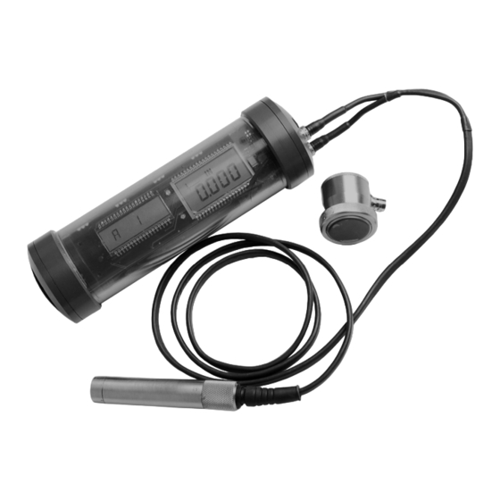
- Page 1 OPERATION MANUAL DAKOTA ULTRASONICS Underwater Material & Coating Thickness Gauge P/N P-185-0004 Rev 1.0, May 2010 GlobalTestSupply www. .com Find Quality Products Online at: sales@GlobalTestSupply.com...
-
Page 2: Table Of Contents
UMX-2 Underwater Material & Coating Thickness Gauge CHAPTER ONE INTRODUCTION - CARE & WARRANTY ........1 CHAPTER TWO QUICK STARTUP GUIDE ............4 CHAPTER THREE OVERVIEW ................7 CHAPTER FOUR MENU & CONNECTOR REFERENCE ........11 CHAPTER FIVE PRINCIPALS OF ULTRASONIC MEASUREMENT ....18 CHAPTER SIX SELECTING THE MEASUREMENT MO DE......22 CHAPTER SEVEN MAKING MEASUREMENTS ..........24... -
Page 3: Chapter One Introduction - Care & Warranty
Dakota Ultrasonics Corporation 1.1 Care & Maintenance The UMX-2 housing is made of a clear PVC material that is very durable and well suited for this application given the following conditions are followed: • Keep the UMX-2 out of direct sunlight as much as possible to avoid any potential ‘crazing’... - Page 4 1.2 Warranty The UMX-2 is protected by a 3 year limited liability: 1. The manufacturer inspects and tests e very UMX-2 for watertight integrity before it is delivered. 2. The manufacturer will repair or replace at the manufacturer's option any housing that proves to be defective in construction or materials within three year of date of delivery.
- Page 5 Dakota Ultrasonics 1.3 Disclaimer Applies to dual element transducers: Inherent in ultrasonic thickness measurement is the possibility that the instrument will use the second rather than the first echo from the back surface of the material being measured. This may result in a thickness reading that is TWICE what it should be.
-
Page 6: Chapter Two Quick Startup Guide
CHAPTER TWO QUICK STARTUP GUIDE The UMX-2 is pre-configured at Dakota Ultrasonics with a specific and common setup. As a result, the gauge should be ready to measure once the transducer has been connected. The UMX-2 can use two different styles of transducers; dual element and single element membrane. - Page 7 Note: in order for the UMX-2 to recognize the transducer that has been attached, it must be in the proper channel location. 2) Press and release the single button located on the end of the UMX-2. The displays should illuminate, and led lights will begin flashing.
- Page 8 Procedure 1) Attached the transducer to the UMX-2. 2) Press and release the single button located on the end of the UMX-2. The displays should illuminate, and led lights will begin flashing. 3) The smaller of the two displays will begin scrolling the current configuration settings of the UMX-2, and an auto zero will be performed.
-
Page 9: Chapter Three Overview
CHAPTER THREE OVERVIEW Turn the UMX-2 on and off using the switch located on the bottom right corner of the keypad. When UMX-2 is initially turned on, a UMX-2 logo will be displayed, accompanied by lots of flashing led lights. The UMX-2 will attempt to ‘auto identify’... - Page 10 These eight vertical bars form the Stability Indicator. When the UMX-2 is idle, only the left-most bar and the underline will be on. When the gauge is making a measurement, six or seven of the bars should be on.
- Page 11 It’s really just that simple! 3.3 Gauge Settings The current settings of the UMX-2 will be displayed on initial power up and every 30 seconds following. This is intended to provide the user with an easy way to confirm the settings at any time, witho ut having to scroll to the specific menus items individually.
- Page 12 UMX-2. • If a custom material type has not been uploaded into the UMX-2, it will not appear in the MATL subdirectory.
-
Page 13: Chapter Four Menu & Connector Reference
UMX-2 STORE Store: This menu displays the current storage location of the UMX-2. This location can refer to either a ‘grid’ cell location, like an Excel spreadsheet, or a sequential format location, depending on which file format was uploaded into the gauge. If the storage facility has been turned off, the menu label will read “MEMOFF”. - Page 14 • Manual – The UMX-2 is also equipped with an “on block” manual zero option. This zero would only be used to reset the internal zero for of the UMX-2, as a reference point for the auto zero. Note: the reference disk is located on the end of the UMX-2 enclosure.
- Page 15 PLUR CUSTOM Material: The UMX-2 includes a list of common material types with standard set velocities. It’s important to note that the velocities associated with these materials are general velocity values only. Materials of the same type, can have varying grades and consistencies.
- Page 16 Top End Cap Bottom End Cap The top & bottom inside end caps are where all connections are made to the UMX-2. The bottom outside end cap also has a ‘zero reference standard’ attached. The diagram above shows the layout and description of the connectors and zero...
- Page 17 Note: There is no polarity associated with connecting a dual element transducer. If a single element membrane style is connected, the dongle ‘must’ be plugged into the connector labeled in the diagram above , in order for the UMX-2 to ‘auto identify’ the single element probe type.
- Page 18 UMX-2 Underwater Material & Coating Thickness Gauge Probe Zero Disk The UMX-2 is equipped with an Auto Zero, which eliminates the user from having to manually perform a zero on a specified zero standard. However, a Manual Zero option has also been included with the UMX-2. This provides the user with the ability to reset the internal zero used for the auto zero as a reset option.
- Page 19 Refer to Diagram: The RS-232 connector is a 2 pin female LEMO connector. It is designed to connect directly from the UMX-2 to a standard AT serial port on a PC or into the supplied Serial to USB converter cable . There are two cables supplied with the UMX-2;...
-
Page 20: Chapter Five Principals Of Ultrasonic Measurement
When the UMX-2 is used underwater as intended, the water itself acts as a couplant. However when the UMX-2 is used above water, it couplant will be required. Typically a high viscosity liquid is used as the medium. - Page 21 UMX-2, and a manual zero is performed by selecting the ‘manual’ sub menu option located in the ‘zero’ menu. If the Auto Zero feature is enabled, a ‘zero reference standard’...
- Page 22 UMX-2 Underwater Material & Coating Thickness Gauge Since pulse-echo only requires one reflection, it is the most sensitive mode for measuring weak reflections (flaws) typically found when measuring heavily corroded metals. V-Path Correction Dual element delay line transducers have two piezoelectric elements mounted at an angle on one end of the delay line.
- Page 23 Dakota Ultrasonics Dual Element Transducer in Echo to Echo mode Pulse Echo Coating Mode – Coating On (PECT) A custom hybrid combination mode using properties from the basic modes along with a group of special techniques and theoretical wave phenomena’s to measure coating and material thicknesses at the same time, while still retaining the ability to locate flaws and pits in materials.
-
Page 24: Chapter Six Selecting The Measurement Mo De
There are a variety of coating transducers in various frequencies available from Dakota. If a dual element transducer is selected with the UMX-2 kit, it will be a coating enabled version. - Page 25 Dakota Ultrasonics Thin materials Use pulse echo mode and a high frequency transducer for these types of applications. The most common transducers are the 7.5MHz and 10MHz models with extra resolution. The higher frequencies provide greater resolution and a lower minimum thickness rating overall.
-
Page 26: Chapter Seven Making Measurements
DakView3 utility software. Refer to page 28 for further info. 7.1 Auto Probe Recognition The first step in using the UMX-2 is to plug the transducer into the gauge and power the unit up. If a single element style transducer is used, be sure that the dongle is connected to the correct LEMO connector, as illustrated above. - Page 27 (PECT), a probe zero will automatically be done following startup. Therefore, if the UMX-2 was previously set to echo-echo mode, the user will first need to set the gauge back to either pulse-echo or pulse-echo coating, before performi ng a probe zero.
- Page 28 1) Be sure all couplant has been removed from the face of the transducer. 2) Press and hold the single UMX-2 button, located on the top end cap, until the top level menu options begin scrolling on the alpha display. Once this occurs, the button can now be released.
- Page 29 UMX-2 will be used as the zero reference standard. 1) Press and hold the single UMX-2 button, located on the top end cap, until the top level menu options begin scrolling on the alpha display. Once this occurs, the button can now be released.
- Page 30 7.3 Material Calibration In order for the UMX-2 to make accurate measurements, it must be set to the correct sound velocity of the material being measured. Different types of materials have different inherent sound velocities. For example, the velocity of sound through steel is about 0.233 inches per microsecond, versus that of aluminum, which is about...
- Page 31 User Selecting Material Type 1) Press and hold the single UMX-2 button, located on the top end cap, until the top level menu options begin scrolling on the alpha display. Once this occurs, the button can now be released. The menu options will scroll one to the next in a time delayed sequence, and will display all the menu options in a continuous loop.
- Page 32 If the material velocity is known, the user may wish to simply enter the velocity number into the UMX-2, rather than have the UMX-2 calcula te the velocity value using a known thickness on a material sample. The steps for entering the velocity...
- Page 33 Dakota Ultrasonics To calibrate the UMX-2 for a specific type of coating using the DakView3 utility software, refer to page 58 for a complete explanation on how to program a known coating velocity into the UMX-2. GlobalTestSupply www. .com Find Quality Products Online at:...
-
Page 34: Chapter Eight Additional Features & Options
UMX-2 can also be powered down manually as follows: Manual Power Off 1) Press and hold the single UMX-2 button, located on the top end cap. Once the UMX-2 is approaching power off status, “POWER”…”OFF”, will be displayed in a loop on the alpha display, and the UMX-2 will shut down. - Page 35 This would be a good time to change the UMX-2 to lower gain setting and see if the reading settles down and become stable. How do I know when to increase the gain? Often times the user will be trying to measure a material that is hard to penetrate or pass sound through.
- Page 36 UMX-2 Underwater Material & Coating Thickness Gauge 3) When the desired gain setting is displayed, immediately press and release the button to set the gain in the UMX-2. For this example, MED has been selected. 4) Press and hold the button to escape out of the sub menu options at any time.
- Page 37 The following procedure explains how to set the lighting option in the UMX-2: Setting Light Option 1) Press and hold the single UMX-2 button, located on the top end cap, until the top level menu options begin scrolling on the alpha display. Once this occurs, the button can now be released.
- Page 38 (LT ON, LT OFF, LAUTO, MEM ON/OFF, UPGRAD). 3) When the desired light option is displayed, immediately press and release the butto n to set the option in the UMX-2. For this example, LT ON has been selected.
-
Page 39: Chapter Nine Thru Paint Measurement Technique
The combination of using both modes is ideal for the advanced inspectors needs. Note: The procedure to select the measurement mode in the UMX-2 is located at the end of this chapter. - Page 40 UMX-2 Underwater Material & Coating Thickness Gauge Disadvantages: Single element transducers are not capable of detecting pits and flaws with a digital thickness gauge, and are typically not used for corrosion inspections on blind surfaces. Since only one crystal is used to both send and receive sound waves, small defects that reflect very little sound energy back to the transducer are ignored, based on the noise created by the same crystal sending the sound wave.
-
Page 41: Chapter Ten Pulse-Echo Coating & Coating Techniques
. Therefore, the UMX-2 has been designed to provide the user with the ability to measure the material and coating thicknesses simultaneously, while maintaining the ability to detect flaws and pits all in a single mode called Pulse-Echo Coating (PECT). - Page 42 The following procedure demonstrates how to enable PECT mode: Enabling PECT Mode 1) Press and hold the single UMX-2 button, located on the top end cap, until the top level menu options begin scrolling on the alpha display. Once this occurs, the button can now be released.
- Page 43 The procedure is outlined below: Performing a Coating Zero 1) Press and hold the single UMX-2 button, located on the top end cap, until the top level menu options begin scrolling on the alpha display. Once this occurs, the button can now be released.
- Page 44 If the coating velocity is known, and other than the factory set velocity of 0.0850 in/µsec (2159 m/sec), the user may wish to program the UMX-2. In order to set the coating velocity, the DakView3 PC software must be used to create a setup, and upload the setup into the UMX-2.
-
Page 45: Chapter Eleven Data Storage - Setup, Edit, & View Files
20 of the same character set. Note: The identifier cannot start or end with a special character. Once a start and end ID are entered into the UMX-2 and the log created, the UMX-2 will automatically generate all the identifiers within that range. - Page 46 UMX-2 Underwater Material & Coating Thickness Gauge Sequential Log Formats Important Note: For the duration of this chapter, all references to GRIDS and SEQ LOGS should be considered synonymous with references to FILES. 11.2 Create New Log Field Definitions Coordinates or Start & Stop ID’s Grid: A grid is defined by using coordinates to define the Top Left and the Bottom Right corners of the grid.
- Page 47 Saving Graphics The UMX-2 provides the user with the ability to save a snapshot of the display screen and all the current settings of the UMX-2 with every reading, or just save the reading only.
- Page 48 UMX-2 Underwater Material & Coating Thickness Gauge Note: This section assumes that DakView3 has already been installed on your PC, has been executed, and ready to go. 1) A log file can be created two different ways; Click the icon button to initiate the ‘New Log’...
- Page 49 Dakota Ultrasonics 3) When all the information has been entered into the fields, click the OK button to create and display the log file. 4) The log file can be saved two different ways; Click the icon button to initiate the ‘SAVE’...
- Page 50 Now that the log file has been created and saved on the PC, the next step is connecting to a PC to transfer the template file into the UMX-2. There are 2 cables included with the UMX-2 kit; LEMO to 9 pin serial and 9 PIN serial to USB.
- Page 51 Dakota Ultrasonics 3) Plug either the RS232 into a serial port, or USB connector into a USB port on the PC. 4) Start the DakView3 utility software. 5) Click on SETTINGS, followed by clicking on COM PORT, to view the list of available ports.
- Page 52 Windows operating system. 6) Power on the UMX-2, and give it a minute to fully boot up. 7) Click the UP ARROW icon to initiate the file transfer. A dialog box will appear, displaying the examples folder created by DakView3 on your desktop.
- Page 53 If anything, other than MEMOFF, is currently displayed, the data logger is already active. 1) Press and hold the single UMX-2 button, located on the top end cap, until the top level menu options begin scrolling on the alpha display. Once this occurs, the button can now be released.
- Page 54 Note: This section assumes the UMX-2 is powered up and ready to go. 1) Press and hold the single UMX-2 button, located on the top end cap, until the top level menu options begin scrolling on the alpha display. Once this occurs, the button can now be released.
- Page 55 11.7 Storing a Measurement Now that a grid or sequential log has been created and uploaded to the UMX-2, and the user is familiar with moving around through the log file, it’s time to take and store a measurement. The following procedures outline this process:...
- Page 56 Note: This section assumes the UMX-2 is powered up and ready to go. Also, the UMX-2 will always return to the left most top level menu item, or the current log file location. This was done to make it convenient for the operator to store measurements without having to scroll through directories.
- Page 57 (CLEAR…A1…CLEAR…A1). 3) When CLEAR or LOCATION(A1) are being displayed, immediately press and release the button to clear the current location in the UMX-2. For this example, A1 has been selected as the storage location. 4) Press and hold the button to escape out of the sub menu options at any time.
- Page 58 UMX-2 Underwater Material & Coating Thickness Gauge 7) Click the DOWN ARROW icon to initiate the file transfer. A dialog box will appear, displaying the examples folder created by DakView3 on your desktop. Alternatively, the upload can be initiated from the menus by clicking the FILE menu option, followed by clicking the DOWNLOAD FROM GAUGE option.
- Page 59 If the file is then saved, the information entered will also be saved with the file. Note: Although the UMX-2 is not equipped with a screen to view an actual live A-Scan waveform, a ‘snapshot’ of the waveform is captured for each and every measurement saved.
-
Page 60: Chapter Twelve Setups - Create, Store, Edit, & Upload
If a user is measuring a material type not preset in the UMX-2, and is not a close enough fit for the specific material, the user can program the UMX-2 for a custom material type, using the DakView3 utility software. - Page 61 Dakota Ultrasonics Note: This section assumes that DakView3 has already been installed on your PC, has been executed, and ready to go. 1) The default setup file can be opened two different ways; Click the icon button to initiate the ‘open’ dialog box, or click FILE, followed by clicking OPEN.
- Page 62 UMX-2 Underwater Material & Coating Thickness Gauge 3) There are two possible velocity settings available; material and coating. The user can enter a known velocity number in either field by clicking in the ‘whitespace’ and the current velocity number, or select a material by clicking on the DOWN ARROW located next to the material type.
- Page 63 Now that the new setup file has been created and saved on the PC, the next step is connecting to a PC to transfer the setup file into the UMX-2. There are 2 cables included with the UMX-2 kit; LEMO to 9 pin serial and 9 PIN serial to USB.
- Page 64 UMX-2 Underwater Material & Coating Thickness Gauge 1) Remove the bottom end cap of the UMX-2, in order to access the LEMO data jack. Remove the rubber plug from the data jack. 2) Plug the LEMO connector into the data jack. Note: align the red pin on the connector with the data jack.
- Page 65 Windows operating system. 6) Power on the UMX-2, and give it a minute to fully boot up. 7) Click the UP ARROW icon to initiate the file transfer. A dialog box will appear, displaying the examples folder created by DakView3 on your desktop.
- Page 66 FILE menu option, followed by clicking the UPLOAD TO GAUGE option. 8) Select the file to be uploaded to the UMX-2. 9) Finally, click the UPLOAD button in the dialog box to start the transfer. A progress bar will appear on the screen during the transfer process, and disappear once the transfer has completed.
-
Page 67: Chapter Thirteen Upgrading The Firmware
Firmware is the actual software, in the UMX-2 itself, that controls the functionality of the gauge. A benefit of the UMX-2, is the ability to upgrade the firmware from your desktop. When changes are made to the firmware, to add features or fix bugs, it can be downloaded from our website and programmed from a remote location. - Page 68 UMX-2 Underwater Material & Coating Thickness Gauge 1) Remove the bottom end cap of the UMX-2, in order to access the LEMO data jack. Remove the rubber plug from the data jack. 2) Plug the LEMO connector into the data jack. Note: align the red pin on the connector with the data jack.
- Page 69 7) Assign a com port 1-4 to the device, and click OK to set the port. 8) Reboot your computer. 9) Power on the UMX-2 that should already be connected to your PC. GlobalTestSupply www.
- Page 70 UMX-2 Underwater Material & Coating Thickness Gauge 10) Press and hold the single UMX-2 button, located on the top end cap, until the top level menu options begin scrolling on the alpha display. Once this occurs, the button can now be released. The menu options will scroll one to the next in a time delayed sequence, and will display all the menu options in a continuous loop.
- Page 71 15) The flash programmi ng process will begin, and continuously display the active status of the blocks transferred. When the process is complete, press N on your keyboard to end the process. 16) The UMX-2 has successfully been upgraded to the latest version of firmware. GlobalTestSupply www.
-
Page 72: Appendix A - Velocity Table
APPENDIX A - VELOCITY TABLE Material sound velocity sound velocity in/us Aluminum 0.2510 6375 Beryllium 0.5080 12903 Brass 0.1730 4394 Bronze 0.1390 3531 Cadmium 0.1090 2769 Columbium 0.1940 4928 Copper 0.1830 4648 Glass (plate) 0.2270 5766 Glycerine 0.0760 1930 Gold 0.1280 3251 Inconel... - Page 73 Dakota Ultrasonics 0.1310 3327 Titanium 0.2400 6096 Tungsten 0.2040 5182 Uranium 0.1330 3378 Water 0.0580 1473 Zinc 0.1660 4216 Zirconium 0.1830 4648 GlobalTestSupply www. .com Find Quality Products Online at: sales@GlobalTestSupply.com...
Need help?
Do you have a question about the UMX-2 and is the answer not in the manual?
Questions and answers