Table of Contents
Advertisement
Quick Links
Distributed by: ABQ Industrial LP USA
Tel: +1 (281) 516-9292 / (888) 275-5772 eFax: +1 (866) 234-0451
Web: https://www.abqindustrial.net E-mail: info@abqindustrial.net
Dakota Ultrasonics ZX-1 Ultrasonic Wall Thickness
Gauge - Instruction Manual
Distributed by: ABQ Industrial LP USA
Tel: +1 (281) 516-9292 / (888) 275-5772 eFax: +1 (866) 234-0451
Web: https://www.abqindustrial.net E-mail: info@abqindustrial.net
Advertisement
Table of Contents

Subscribe to Our Youtube Channel
Related Manuals for DAKOTA ULTRASONICS ZX-1


Summary of Contents for DAKOTA ULTRASONICS ZX-1
- Page 1 Distributed by: ABQ Industrial LP USA Tel: +1 (281) 516-9292 / (888) 275-5772 eFax: +1 (866) 234-0451 Web: https://www.abqindustrial.net E-mail: info@abqindustrial.net Dakota Ultrasonics ZX-1 Ultrasonic Wall Thickness Gauge - Instruction Manual Distributed by: ABQ Industrial LP USA Tel: +1 (281) 516-9292 / (888) 275-5772 eFax: +1 (866) 234-0451...
-
Page 2: Table Of Contents
CONTENTS CHAPTER ONE INTRODUCTION ..............1 1.1 D ......................... 1 ISCLAIMER CHAPTER TWO KEYPAD, MENU, DISPLAY & CONNECTORS ..... 2 2.1 ON/OFF/ENTER K …..................... 2 2.2 PRB 0 K … ........................2 2.3 VEL K ….......................... 3 2.4 LIGHT K …. -
Page 3: Chapter One Introduction
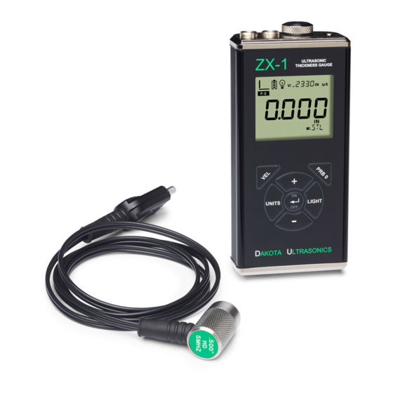
CHAPTER ONE INTRODUCTION The Dakota Ultrasonics model ZX-1 is a basic dual element thickness gauge with the ability to locate blind surface pitting and internal defects/flaws in materials. Based on the same operating principles as SONAR, the ZX-1 is capable of measuring the thickness of various materials with accuracy as high as ... -
Page 4: Chapter Two Keypad, Menu, Display & Connectors
2.2 PRB 0 Key The PRB 0 key is used to “zero” the ZX-1 in much the same way that a mechanical micrometer is zeroed. If the gauge is not zeroed correctly, all of the measurements that the gauge makes may be in error by some fixed value. -
Page 5: Vel Key
ZX-1 Ultrasonic Thickness Gauge 2.3 VEL Key The VEL key is used to enter and exit the ZX-1's calibration mode. This mode is used to adjust the sound velocity value that the ZX-1 will use for a given material type. Enter a known velocity value for specific material type, or manually continue adjusting the value until the ZX-1 displays the correct thickness value using a test sample or calibration block with a known thickness. -
Page 6: The Display
The icons and segments that will be used with the ZX-1 are shown in the diagram above. -
Page 7: The Transducer
G. Small 14 Segment: The material velocity, speed the sound wave travels through a given medium/material, is displayed in this area, informing the user what material the ZX-1 is currently calibrated too. This area is also used for alpha messages in the menu and edit modes. - Page 8 The Stability Indicator should have six or seven bars darkened, and a number should appear in the display. If the ZX-1 has been properly "zeroed" (see page 13) and set to the correct sound velocity (see page 14), the number in the display will indicate the actual thickness of the material directly beneath the transducer.
-
Page 9: Top End Cap
When the transducer is removed from the surface, the display will hold the last measurement made. 2.9 Top End Cap The top end cap is where all connections are made to the ZX-1. The diagram above shows the layout and description of the connectors: Transducer Connectors Refer to Diagram: The transducer connectors and battery cover/probe zero disk are located on the ZX-1’s top end cap. -
Page 10: Chapter Three Principals Of Ultrasonic Measurement
CHAPTER THREE PRINCIPALS OF ULTRASONIC MEASUREMENT 3.1 Time versus thickness relationship Ultrasonic thickness measurements depend on measuring the length of time it takes for sound to travel through the material being tested. The ratio of the thickness versus the time is known as the sound velocity. In order to make accurate measurements, a sound velocity must be determined and entered into the instrument. -
Page 11: Temperature
(reflection). A manual zero must be performed by placing the transducer on the reference disk located on top of the ZX-1, and the PRB 0 key pressed to establish a zero point for the transducer connected. - Page 12 Dakota Ultrasonics surface of the test material does not have to be as flat in order to obtain good measurements. Dual element delay line transducers are have a usable range of 0.025” and up, depending on the material, frequency, and diameter.
-
Page 13: Chapter Four Selecting The Measurement Mode
CHAPTER FOUR SELECTING THE MEASUREMENT MODE 4.1 Which mode & transducer do I use for my application? High penetration plastics and castings The most common mode for these types of applications is pulse-echo. Cast iron applications require 1 - 5MHz frequencies, and cast aluminum requires a 7 - 10MHz frequency depending on the thickness. - Page 14 Dakota Ultrasonics Noisy Material Materials such as titanium, stainless steel, and aluminum may have inherent surface noise issues or mirroring effect. Higher frequency transducers 7 – 10MHz offer improved resolution to avoid erroneous measurements. Restricted access Measuring materials with extreme curvatures or restricted access are best suited for...
-
Page 15: Chapter Five Making Measurements
Material Calibration section on page 14. 5.1 Probe zero Setting the zero point of the ZX-1 is important for the same reason that setting the zero on a mechanical micrometer is important. It must be done prior to calibration, and should be done throughout the day to account for any temperature changes in the probe. -
Page 16: Velocity Calibration
5.2 Velocity Calibration In order for the ZX-1 to make accurate measurements, it must be set to the correct sound velocity of the material being measured. Different types of materials have different inherent sound velocities. - Page 17 ZX-1 Ultrasonic Thickness Gauge Note: Pressing the key prior to pressing the key will abort the cal routine without saving any changes. 3) Press the key to set the velocity value and return to the measurement screen. The new velocity value will be shown at the top of the display.
-
Page 18: Chapter Six Additional Features
(IN/MM). 6.2 Light The ZX-1 uses a custom glass segmented display that is equipped with a backlight for use in low light conditions. The options are on/off/auto, where the auto setting only lights the display when the gauge is coupled to the material and receiving a measurement. -
Page 19: Lock
6.3 Lock The lock feature was built into the ZX-1 for the purpose of locking the operators out of editing any of the gauge settings, for purposes of consistency between operators. When the lock feature is enabled, the gauge calibration functionality cannot be altered, as well as any of the individual features in the gauge. -
Page 20: Factory Defaults
ZX-1 on 6.4 Factory Defaults The ZX-1 can be reset to factory defaults at any time to restore the original gauge settings. This should only be used if the gauge is not functioning properly, or perhaps multiple features have been enabled and a clean start is needed. -
Page 21: Appendix A - Velocity Table
APPENDIX A - VELOCITY TABLE Material sound velocity sound velocity in/us Aluminum 0.2510 6375 Beryllium 0.5080 12903 Brass 0.1730 4394 Bronze 0.1390 3531 Cadmium 0.1090 2769 Columbium 0.1940 4928 Copper 0.1830 4648 Glass (plate) 0.2270 5766 Glycerine 0.0760 1930 Gold 0.1280 3251 Inconel... - Page 22 Dakota Ultrasonics 0.1310 3327 Titanium 0.2400 6096 Tungsten 0.2040 5182 Uranium 0.1330 3378 Water 0.0580 1473 Zinc 0.1660 4216 Zirconium 0.1830 4648...
-
Page 23: Appendix B- Application Notes
At such elevated temperatures, it is recommended that the user perform calibration on a sample piece of known thickness, which is at or near the temperature of the material to be measured. This will allow the ZX-1 to correctly calculate the velocity of sound through the hot material. - Page 24 Dakota Ultrasonics the probe be left in contact with the surface for as short a time as needed (intermittent contact) to acquire a stable measurement. Measuring laminated materials Laminated materials are unique in that their density (and therefore sound-velocity) may vary considerably from one piece to another. Some laminated materials may even exhibit noticeable changes in sound-velocity across a single surface.
- Page 25 Additionally, Dakota Ultrasonics warrants transducers and accessories against such defects for a period of 90 days from receipt by the end user. If Dakota Ultrasonics receives notice of such defects during the warranty period, Dakota Ultrasonics will either, at its option, repair or replace products that prove to be defective.
Need help?
Do you have a question about the ZX-1 and is the answer not in the manual?
Questions and answers