
Related Manuals for Leuze electronic BPS 34


Summary of Contents for Leuze electronic BPS 34
- Page 1 BPS 34 Bar code positioning system - PROFIBUS DP O r i g in a l op e r a ti n g i n s tr uc t i o ns...
-
Page 2: Table Of Contents
Competent persons......................5 Exemption of liability ......................6 Laser safety notices ......................6 Fast commissioning steps at a glance ................8 Technical data of BPS 34 ....................14 General specifications BPS 34 ..................14 Dimensioned drawings....................... 15 Electrical connection ......................17 4.3.1... - Page 3 Table of contents Mounting........................... 38 Mounting the BPS 34 ......................38 Device arrangement......................41 Mounting the bar code tape ....................42 Device parameters and interfaces.................. 43 PROFIBUS......................... 43 8.1.1 General information........................43 8.1.2 Electrical connection ........................43 8.1.3 PROFIBUS address ........................46 8.1.4 General information on the GSD file ....................46...
-
Page 4: General Information
This symbol indicates text passages containing important information. Declaration of Conformity The bar code positioning system BPS 34, the modular connector hood MS 34 103/ MS 34 105, and the optional modular service display MSD 1 101 have been developed and manufactured in accordance with the applicable European standards and directives. -
Page 5: Safety
BPS 34 in a PROFIBUS system. The modular service display MSD 1 101, which is optionally available, displays operational data of the BPS 34 and is used as a simple means of access to the service interface of the MS 34 105. -
Page 6: Foreseeable Misuse
The device must not be tampered with and must not be changed in any way. The device must not be opened. There are no user-serviceable parts inside. Repairs must only be performed by Leuze electronic GmbH + Co. KG. Competent persons Connection, mounting, commissioning and adjustment of the device must only be carried out by competent persons. -
Page 7: Exemption Of Liability
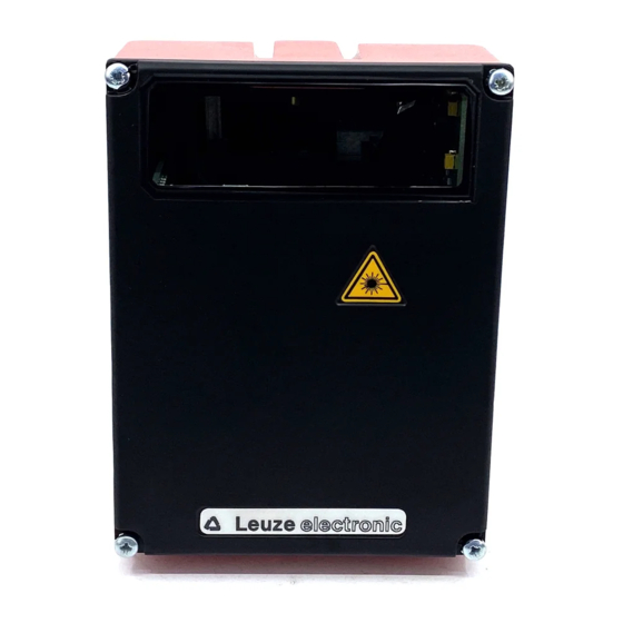
Safety Exemption of liability Leuze electronic GmbH + Co. KG is not liable in the following cases: • The device is not being used properly. • Reasonably foreseeable misuse is not taken into account. • Mounting and electrical connection are not properly performed. - Page 8 Affix laser information and warning signs! Laser information and warning signs are attached to the device (see Figure 2.1): A Laser aperture B Laser warning sign C Laser information sign with laser parameters Figure 2.1:Laser apertures, laser warning and information signs Leuze electronic BPS 34...
-
Page 9: Fast Commissioning Steps At A Glance
Description of the BPS 34 functions The BPS 34 uses visible red laser light to determine its position relative to the bar code tape. This essentially takes place in three steps: Reading a code on the bar code tape... - Page 10 Attention! For the position calculation, the scanning beam of the BPS 34 must be incident on the bar code tape without interruption. Ensure that the scanning beam is always incident on the bar code tape when the system is moving.
- Page 11 Fast commissioning steps at a glance Connecting the voltage supply and PROFIBUS The BPS 34, in combination with an MS 34 103 or MS 34 105, is connected via M12 connectors. Connecting the voltage supply The voltage supply is connected via the PWR IN M12 connection.
- Page 12 (B-coded) (B-coded) (A-coded) Figure 3.3:BPS 34 with MS 34 103/MS 34 105 – DP IN and DP OUT connections Setting the PROFIBUS address The PROFIBUS address must be set in the MS 34 10x connector plug hood. The correct address setting on the PROFIBUS network is indicated by the green LED on the MS 34 10x.
- Page 13 Fast commissioning steps at a glance PROFIBUS manager Install the GSD file associated with the BPS 34… in the PROFIBUS manager of your control. Activate the desired modules (at least module 1 - position value). Figure 3.5:Example PROFIBUS manager Store the slave address for the BPS 34 in the PROFIBUS manager. Ensure that the address is the same as the address configured in the device.
- Page 14 Figure 3.7:BPS 34 with MS 34 103/MS 34 105 - MSD connection The BPS 34 can be accessed via the MS 1 101 using the service interface. Note! Changes which were made via the service interface on the BPS 34 are lost following initial- ization on the PROFIBUS. Leuze electronic...
-
Page 15: Technical Data Of Bps 34
Technical data of BPS 34 Technical data of BPS 34 General specifications BPS 34 Optical data Light source Laser diode Beam deflection Via rotating polygon wheel Reading distance See reading field (Figure 4.3.5) Optical window Glass with scratch-resistant indium coating Laser class 2 acc. -
Page 16: Dimensioned Drawings
For devices with integrated heating (…H models), window heating is in constant operation. Regulation of device-internal heating is temperature dependent. Dimensioned drawings BPS 34 SM 100 / BPS 34 SM 100 H / BPS 34 SM 100 HT Rear view Top view... - Page 17 Technical data of BPS 34 MS 34 103 / MS 34 105 MS 34 103 MS 34 105 Note! A = BPS 34 The MSD and SW IN/OUT all dimensions in mm connections are sealed with caps upon delivery. Figure 4.2:Dimensioned drawing MS 34 103 / MS 34 105...
-
Page 18: Electrical Connection
Technical data of BPS 34 Electrical connection The BPS 34 can be connected via the MS 34 103/MS 34 105 using M12 connectors. For the locations of the individual device connections, please refer to the device detail shown in Figure 4.3. - Page 19 Plug Plug (B-coded) (B-coded) (A-coded) Figure 4.3:Pin assignment of the BPS 34 with MS 34 103 / MS 34 105 Attention! Degree of protection IP 65 is achieved only if the connectors and caps are screwed into place! BPS 34...
-
Page 20: Pwr In - Voltage Supply And Switching Input/Output
Functional earth (housing) Figure 4.4:Pin assignment - PWR IN Connecting the functional earth PE BPS 34 with MS 34 103/MS 34 105 connector hood: Connect PE to PIN 5 of the M12 connector PWR IN for voltage supply! Note! Programming of the switching input/switching output is performed via module 7 (Switching input) and module 8 (Switching output). -
Page 21: Dp In - Profibus Dp Incoming
Technical data of BPS 34 4.3.2 DP IN - PROFIBUS DP incoming DP IN (5-pin plug, B-coded) Name Comment DP IN A (N) 5VDC for bus termination A (N) Receive/transmit data A-line (N) GND 3 Functional earth for bus termination... -
Page 22: Sw In/Out - Switching Input/Switching Output
Technical data of BPS 34 4.3.4 SW IN/OUT – Switching input/switching output SW IN/OUT (5-pin socket, A-coded) Name Comment SW IN/OUT Supply voltage for sensor system SWOUT (VOUT identical to VIN at PWR IN) VOUT Without optics heating: +10 … +30VDC With optics heating: +22 …... -
Page 23: Bps 34 Reading Field Curve
Technical data of BPS 34 Connecting the switching input / switching output The BPS 34 is provided with a switching input and a switching output. The connection is performed as shown in Figure 4.8: SW IN/OUT connector SWIN V OUT... -
Page 24: Ms 34
MS 34 103 and MS 34 105 modular connector hoods A modular connector hood of type MS 34 103 or MS 34 105 is part of every BPS 34. The two connector hoods are used to connect the BPS 34 to the PROFIBUS. For this, they feature one DP IN and one DP OUT connection each, as well as switches for address setting. -
Page 25: Dimensioned Drawings
MS 34 … / MSD 1 101 connection units 5.1.3 Dimensioned drawings MS 34 103 MS 34 105 A = BPS 34 Note! The MSD and SW IN/OUT all dimensions in mm connections are sealed with caps upon delivery. Figure 5.1:Dimensioned drawing MS 34 103 / MS 34 105... -
Page 26: Electrical Connection
Error on the PROFIBUS, error cannot be resolved by a reset of the control Orange, continuous light Service operation active Note: The LED remains off until the BPS 34 is recognized by the PROFIBUS. Only after the PROFIBUS has addressed the BPS 34 for the first time, the following state descrip- tions apply. -
Page 27: Msd 1 101 Modular Service Display
The RS 232 service interface of the BPS 34 is located on the 9-pin sub-D connector of the MSD. To connect the MSD 1 101 to the MS 34 105, an 8-pin cable (M12) with a length of 2m is used (see chapter 10.3 "Accessories - Modular service display"). -
Page 28: Dimensioned Drawing
MSD 1 101 and is designed as a 9-pin sub-D connector. The pin configuration of the 9-pin sub-D connector corresponds to a standard RS 232 interface: • PIN 2 = RxD • PIN 3 = TxD • PIN 5 = GND Leuze electronic BPS 34... -
Page 29: Bar Code Tape
200m each (see chapter 10.9 "Type overview: Bar code tape" on Page 98). Figure 6.1:Roll with bar code tape Features: • Robust and durable polyester adhesive tape • High dimensional stability • Max. length 10,000m • Self-adhesive, high adhesive strength BPS 34 Leuze electronic... -
Page 30: Technical Data Of The Bar Code Tape
No shrinkage, tested according to DIN 30646 Curing Final curing after 72 h, the position can be detected immediately by the BPS 34 after the BCB is affixed Heat expansion Due to the high elasticity of the BCB, heat expansion of... -
Page 31: Mounting The Bar Code Tape
BPS. The gap must not be greater than the distance from one cut mark to the next (max. one label). max. 40 mm 000020 000024 000028 000032 000036 Cut mark Figure 6.3:Gap in the cut bar code tape BPS 34 Leuze electronic... - Page 32 If the scanning beam cannot completely scan any label, the BPS 34 returns the value 0. As soon as the BPS 34 can again scan a complete label, it calculates the next position value.
- Page 33 Bar code tape 007000 Figure 6.4:Partial cutting of the bar code tape in curves BPS 34 Leuze electronic...
-
Page 34: Control Bar Codes
Control bar codes With the aid of control bar codes, which are simply affixed over the bar code tape at the necessary positions, functions can be activated and deactivated in the BPS 34. Structure of the control bar codes The control bar codes utilize code type Code128 with character set B; the position bar codes, on the other hand, utilize Code128 with character set C. -
Page 35: Controllable Functions
If the center of the BPS 34 reaches the transition point of the control bar code, the device switches to the second tape, provided the next position label is in its scan- ning beam. - Page 36 (see Figure 6.8). In this situation, the hysteresis of ±5mm is irrelevant. If, however, the device is stopped within the hysteresis on the "MVS" label and the direction changed, the starting position values have an inaccuracy ±5mm. Leuze electronic BPS 34...
-
Page 37: Repair Kit
If only the "MVS" label is located in the scanning beam, the voltage on the BPS 34 must not be switched off. Otherwise the BPS 34 will return a position value of zero when the voltage is switched back on. - Page 38 Cut the code strips and concatenate them. It is important that the code content always increases or decreases in blocks of 4 cm. Figure 6.9:Printer settings for BCB repair kit 40 mm 000020 000024 000028 000032 000036 Figure 6.10:Checking the print results of the BCB repair kit Leuze electronic BPS 34...
-
Page 39: Mounting
Figure 7.1:BPS 34 mounting options BT 56 mounting device The BT 56 mounting device is available for mounting the BPS 34 using the fastening grooves. It is designed for rod mounting (Ø 16mm to 20mm). For order guide, please refer to Chapter 10.6 on Page 95. - Page 40 BPS Clamp profile for mounting to round or oval pipes Ø 16 … 20mm all dimensions in mm A Rod holder, turnable 360° B Rods Ø 16 … 20mm Figure 7.2:BT 56 mounting device Leuze electronic BPS 34...
- Page 41 Attention! For the position calculation, the scanning beam of the BPS 34 must be incident on the bar code tape without interruption. Ensure that the scanning beam is always incident on the bar code tape when the system is moving.
-
Page 42: Device Arrangement
• On the BPS 34, the beam is not emitted perpendicular to the cover of the housing, but with an angle of 10° towards the top. This angle is intended to prevent total reflection on the bar code tape. -
Page 43: Mounting The Bar Code Tape
Mounting the bar code tape The BPS 34 and bar code tape combination is mounted in such a way that the scanning beam is uninterrupted and is incident on the bar code tape as described in Figure 7.4 on Page 41. -
Page 44: Device Parameters And Interfaces
8.1.1 General information The BPS 34 with MS 34 103/MS 34 105 is designed as a PROFIBUS device (PROFIBUS DP-V0 acc. to IEC 61784-1) with a baud rate of 12MBd. The functionality of the device is defined via parameter sets which are clustered in modules. These modules are contained in a GSD file. - Page 45 Receive/transmit data B-line (P) B (P) Functional earth M12 socket Thread Functional earth (housing) (B-coded) Figure 8.3:Pin assignment - DP IN Attention! Degree of protection IP 65 is achieved only if the connectors and caps are screwed into place! BPS 34 Leuze electronic...
- Page 46 For further information on this topic, refer to Chapter 10.8 on Page 97. The BPS 34 can be used in combination with an MS 34 103/MS 34 105 to branch out the PROFIBUS network. The continuing network is connected via DP OUT.
-
Page 47: Profibus Address
You can find the GSD file at www.leuze.com. This file stores all the data required for the operation of the BPS 34. This data consists of device parameters required for the operation of the BPS 34 and the definition of the control and status bits. -
Page 48: Structure Of The Gsd Modules
The BPS 34 does not permanently store parameters changed via the PROFIBUS. Following Power off/on, the currently configured parameters are downloaded from the PROFIBUS manager. If no PROFIBUS manager is available following Power off/on, the BPS 34 acti- vates its stored default settings. -
Page 49: Overview Of The Gsd Modules
(O) Start event (O) Stop event (O) BPS standby Measurement value (P) Maximum permitted measurement length acquisition (P) Minimum permitted measurement length Page 66 Measurement value (P) Integration depth preparation (O) Counting direction for position calculation Page 67 BPS 34 Leuze electronic... - Page 50 Service (O) Reset to factory settings Page 78 Speed (I) Current speed Page 79 (P) Resolution (P) Scaling factor Speed parameters (P) Integration depth Page 80 (P) Tolerance time (on error message) (P) Error output delay Leuze electronic BPS 34...
- Page 51 (O) Limit value Page 89 limit values (O) Hysteresis (O) Range start (O) Range end (P) Real length Tape value correction (P) Range start Page 91 (P) Range end Table 8.1: Overview of the GSD modules BPS 34 Leuze electronic...
-
Page 52: Detailed Description Of The Modules
The parameters and input/output data within a module are alphanumerically labeled from … Example: Static preset value in [mm] parameter in module 3 only becomes active when the preset teach occurs via module 12 or 3 Leuze electronic BPS 34... - Page 53 Output of the current position Scaled – Position (for a resolution in mm) value Input data length: 4 byte Note! A negative number is represented in the input data by a 1 in the most significant bit. Output data None BPS 34 Leuze electronic...
- Page 54 Device parameters and interfaces 8.1.7.2 Module 2: Resolution Description With this module, the resolution for the position value of module 1 is defined. The BPS 34 also performs a rounding correction (The position value is divided by the defined value range).
- Page 55 The preset remains stored in the BPS 34 and remains active even following a new start. In order for the BPS 34 to again output the position value without the preset, bit 0.1 in the output data must be set.
- Page 56 Default Unit CR to data addr. type module Read in the preset value 0->1 = Teach – – Preset teach Preset value is deactivated 0->1 = Reset – – Preset reset Output data length: 1 byte Leuze electronic BPS 34...
- Page 57 The preset remains stored in the BPS 34 and remains active even following a new start. In order for the BPS 34 to again output the tape value, bit 0.1 in the output data must be set (preset reset). The preset value is transmitted to the BPS 34 together with the output data of the PROFIBUS master.
- Page 58 When entering the offset value, the scaling in module 6 must be taken into account. Hex coding of module 5 "Offset value" The value listed in the table shows the hex coding of the default settings. 00 00 00 00 Input data None Output data None Leuze electronic BPS 34...
- Page 59 • Dynamic position limit values 1 and 2 (modules 16 and 17) • Hysteresis of dynamic position limit values 1 and 2 (modules 16 and 17) The static preset or dynamic preset modules (module 3 or module 4) are not affected by the scaling. BPS 34 Leuze electronic...
- Page 60 Device parameters and interfaces Hex coding of module 6 "Scaling" The value listed in the table shows the hex coding of the default settings. 03 E8 Input data None Output data None Leuze electronic BPS 34...
- Page 61 The parameter influences the timing during switch-on. unsign Start-up 0 … 65,535 – delay in [ms] The parameter defines the mini- mum pulse duration of the input signal. unsign 0 … 65,535 – Pulse dura- tion in [ms] BPS 34 Leuze electronic...
- Page 62 Input data Description Rel. Data Value range Default Unit CR to addr. type module 0: Input is not active Signal state of the switching input – – 1: Input is active State Input data length: 1 byte Leuze electronic BPS 34...
- Page 63 - position limit value 2 not 15 + 17 reached 1 + 9 - erroneous measurement 1 + 9 - successful measurement - PROFIBUS pos. edge - PROFIBUS neg. edge - speed limit value reached - speed limit value not reached BPS 34 Leuze electronic...
- Page 64 This bit can be used to operate Switching the switching output if the "PRO- 0 -> 1: Positive edge – – output FIBUS edge" function is config- 1 -> 0: Negative edge PROFIBUS ured. edge Output data length: 1 byte Leuze electronic BPS 34...
- Page 65 Time for stop timeout 0 … 65,535 10,000 – Stop time- out in [ms] Parameter length: 4 byte Hex coding of module 9 "Control" The value listed in the table shows the hex coding of the default settings. BPS 34 Leuze electronic...
- Page 66 • Init: Base setting during initial startup of the BPS 34 • Idle: The BPS 34 is in idle state (scanning beam is off, but motor is running) • Measure: The BPS 34 is in measurement state (data are output in module 1) •...
- Page 67 Note! The standby function can only be activated while in "Measure" state. This function switches off the motor and laser. It takes approx. 2seconds to switch the BPS 34 back on (valid mea- surement values at the interface). In "Idle" state, the motor continues to run. Only the laser is switched off. It takes approx.
- Page 68 In order to obtain positive or negative position values depending on the direction of move- ment of the BPS 34, the counting direction can be selected as normal or inverted in the output data of this module.
- Page 69 Default Unit CR to data addr. type module Counting direction for position 0: Normal – – Counting calculation 1: Inverted direction Output data length: 1 byte Note! The BPS 34 is set as follows by default: BPS 34 Leuze electronic...
- Page 70 Counting direction "normal" Position value = tape value 1,400,000 mm 0 mm 10,000,000 mm Counting direction Counting direction "inverted" Position value 8,600,000mm (=10,000,000mm - tape value) 0 mm 10,000,000 mm Counting direction Figure 8.12:Counting direction for position calculation Leuze electronic BPS 34...
- Page 71 8.1.7.13 Module 12: Status Note! Underlined in the CR column are the modules which must be activated in addition to the cur- rent module. Description This module supplies various BPS 34 status information to the PROFIBUS master. Parameters None Input data Input data Description Rel.
- Page 72 0 … 255 sure- – window for the min-max values. period ments Parameter length: 2 byte Hex coding of module 13 "Min./max. position" The value listed in the table shows the hex coding of the default settings. Leuze electronic BPS 34...
- Page 73 Output data length: 8 byte Note! With "MinMax reset", the input data are reset to 155812h. With this module, the settings for the Preset (module 3), Offset (module 5) and Scaling (module 6) modules must be taken into account. BPS 34 Leuze electronic...
- Page 74 00 00 00 00 00 00 Input data None Output data None Note! With this module, the settings for the Preset (module 3), Offset (module 5) and Scaling (module 6) modules must be taken into account. Leuze electronic BPS 34...
- Page 75 00 00 00 00 00 00 Input data None Output data None Note! With this module, the settings for the Preset (module 3), Offset (module 5) and Scaling (module 6) modules must be taken into account. BPS 34 Leuze electronic...
- Page 76 1 in module 12 is set and, if configured, the switching output is appropriately set. The limit value is transferred to the BPS 34 together with the output data of this module by the PROFIBUS master.
- Page 77 2 in module 12 is set and, if configured, the switching output is appropriately set. The limit value is transferred to the BPS 34 together with the output data of this module by the PROFIBUS master.
- Page 78 The availability of the system is thereby ensured. No new values are delivered by the BPS 34, however, for a period of time extending up to the config- ured tolerance time. With the "delay error output" parameter, an integration error (corre- sponds to a missing position value) can be signaled immediately or after the tolerance time has elapsed.
- Page 79 8.1.7.20 Module 19: Service Description The "service" function is used to reset the parameter set of the BPS 34 to default settings. This reset only occurs directly in the BPS 34. After the reset function has been activated, the device carries out a reset and is freshly configured on the PROFIBUS. This results in the reactivation of all modules and parameter settings selected in the PROFIBUS project.
- Page 80 Outputs the current speed with the configured resolution and the desired scaling factor. In order for the speed to be calculated in the BPS 34 and output in this module, module 22 (Control speed measurement) must also be activated in the PROFIBUS project.
- Page 81 [ms] Delays the output of a speed unsign 0: No, error delay deactivated Delay error by the configured toler- – 1: Yes, error delay activated speed error ance time. output Parameter length: 7 byte BPS 34 Leuze electronic...
- Page 82 Response time [ms] 4 (default) Hex coding of module 21 "Speed parameters" The value listed in the table shows the hex coding of the default settings. 03 E8 00 32 Input data None Output data None Leuze electronic BPS 34...
- Page 83 Either by output bit 0.1 or by ment stop the switching input function mode Parameter length: 2 byte Hex coding of module 22 "Speed measurement control" The value listed in the table shows the hex coding of the default settings. BPS 34 Leuze electronic...
- Page 84 • Init: Base setting during initial startup of the BPS 34 • Idle: The BPS 34 is in idle state (scanning beam is off, but motor is running) • Measure: The BPS 34 is in measurement state (data are output in module 1) •...
- Page 85 Device parameters and interfaces 8.1.7.24 Module 23: Speed measurement status Description This module supplies various status information regarding the speed measurement of the BPS 34 to the PROFIBUS master. Parameters None Input data Input data Description Rel. Data Value range...
- Page 86 The "Dynamic preset" module (module 4), the "MVS label" function and the "error tolerance time" can be used to activate the messages of the input data. Depending on the con- … figuration, these may be normal states. Output data None Leuze electronic BPS 34...
- Page 87 CR to addr. type module Minimum speed for detected unsign 0 … 10,000,000 Scaled Min. speed period. Maximum speed for detected unsign 0 … 10,000,000 Scaled period. Max. speed Input data length: 8 byte Output data None BPS 34 Leuze electronic...
- Page 88 Speed limit Limit value is compared to the unsign 0 … 20,000 mm/s value 1 in current speed. [mm/s] Relative offset of the switching unsign Speed hys- 0 … 20,000 mm/s point. teresis 1 in [mm/s] Leuze electronic BPS 34...
- Page 89 -10,000,000 … 10,000,000 start limit tored starting from this position. value 4 in [mm] The speed limit value is moni- Range end sign32 -10,000,000 … 10,000,000 tored up to this position. limit value 4 in [mm] BPS 34 Leuze electronic...
- Page 90 00 00 00 00 Input data None Output data None 8.1.7.27 Module 26: Dynamic speed limit value Note! Underlined in the CR column are the modules which must be activated in addition to the cur- rent module. Leuze electronic BPS 34...
- Page 91 PROFIBUS master. The transferred values are activated by bit 0.0, i.e. if this bit is set, the BPS 34 compares the current speed with the new limit value conditions. Parameters...
- Page 92 0 … 10,000,000 – start in position. [mm] The tape value is corrected with sign32 0 … 10,000,000 10,000,000 – Range end the real length up to this position. in [mm] Parameter length: 10 byte Leuze electronic BPS 34...
- Page 93 Hex coding of module 27 "Tape value correction" The value listed in the table shows the hex coding of the default settings. 27 10 00 00 00 00 00 98 96 80 Input data None Output data None BPS 34 Leuze electronic...
-
Page 94: Diagnostics And Troubleshooting
• Device not yet recognized by the PROFIBUS. LED MS 34 10x = Note: The LED remains off until "off" the BPS 34 is recognized by the PROFIBUS. Only after the PROFIBUS has addressed the BPS 34 for the first time, the following state descriptions apply. - Page 95 Customer data (please complete) Leuze service fax number: +49 7021 573-199 Device type: Company: Contact person/department: Phone (direct dial): Fax: Street / no.: ZIP code / City: Country: BPS 34 Leuze electronic...
-
Page 96: Type Overview And Accessories
Accessories - Modular connector hoods Part no. Type designation Comment 50037230 MS 34 103 Modular connector hood for BPS 34 with three M12 connectors 50037231 MS 34 105 Modular connector hood for BPS 34 with five M12 connectors 10.3 Accessories - Modular service display Part no. -
Page 97: Accessories - Ready-Made Cables For Voltage Supply
Type designation Comment 50104557 K-D M12A-5P-5m-PVC M12 socket for PWR IN, axial plug outlet, open cable end, cable length 5m 50104559 K-D M12A-5P-10m-PVC M12 socket for PWR IN, axial plug outlet, open cable end, cable length 10m BPS 34 Leuze electronic... -
Page 98: Accessories - Ready-Made Cables For Profibus Connection
Thread Bare A (N) N.C. 3 N.C. N.C. B (P) M12 plug (B-coded) 1 Conductor with insulation red 2 Conductor with insulation green 3 Drain wire 4 Fibrous fleece Bild 10.1:Cable structure of PROFIBUS connection cable Leuze electronic BPS 34... -
Page 99: 10.8.3 Technical Data Of Profibus Connection Cable
Bar code tape, 80m length 50038890 BCB 090 Bar code tape, 90m length 50037493 BCB 100 Bar code tape, 100m length 50040042 BCB 110 Bar code tape, 110m length 50040043 BCB 120 Bar code tape, 120m length BPS 34 Leuze electronic... - Page 100 BCB 200 Bar code tape, 200m length BCB / special lengths starting at 50037495 Bar code tape with special length and special height 150m 50102600 BCB special length 25mm high Bar code tape special length 25mm high Leuze electronic BPS 34...
-
Page 101: Maintenance
11.1 General maintenance information Usually, the BPS 34 does not require any maintenance by the operator. In the event of dust build-up, clean the optical window with a soft cloth; use a cleaning agent (commercially available glass cleaner) if necessary. -
Page 102: Appendix
Appendix Appendix 12.1 EC Declaration of Conformity Leuze electronic BPS 34... - Page 103 ..... . . 15 BPS 34 ....16 MS 34 103 .
- Page 104 ..... . . 38 BPS 34 ......38 BT 56 .
- Page 105 ....21 Switching input ....21 Switching output BPS 34 Leuze electronic...
- Page 106 ......95 BPS 34 ....47 Universal module .
Need help?
Do you have a question about the BPS 34 and is the answer not in the manual?
Questions and answers