
Subscribe to Our Youtube Channel
Related Manuals for Smartgen HMC6


Summary of Contents for Smartgen HMC6
- Page 1 HMC6 POWER MANAGEMENT CONTROLLER USER MANUAL SMARTGEN (ZHENGZHOU) TECHNOLOGY CO.,LTD.
- Page 2 SmartGen Technology at the address above. Any reference to trademarked product names used within this publication is owned by their respective companies. SmartGen Technology reserves the right to change the contents of this document without prior notice. Table 1 - Version history Date...
- Page 3 This manual is suitable for HMC6 Power Management controller only. Table 2 - Notation Clarification Sign Instruction Highlights an essential element of a procedure to ensure correctness. NOTE Indicates a procedure or practice, which, if not strictly observed, could result in damage CAUTION! or destruction of equipment.
-
Page 4: Table Of Contents
9.3 CONNECTION ..............................31 9.3.1 TYPICAL APPLICATION DIAGRAM ...................... 31 9.3.2 AC WIRE CONNECTION (3 PHASE 3 WIRE) ..................31 9.3.3 AC WIRE CONNECTION (SINGLE PHASE 2 WIRE) ................32 HMC6 Power Management Controller User Manual Page 4 of 87... - Page 5 STEP 2: SEMI-AUTO PARALLEL OPERATION OFF-LOAD ................ 85 12.3 STEP 3: SEMI-AUTO PARALLEL OPERATION ON-LOAD ................. 85 12.4 STEP 4: AUTOMATIC PARALLEL OPERATION ..................85 13. INSTALLATION ..............................86 14 FAULT FINDING..............................87 HMC6 Power Management Controller User Manual Page 5 of 87...
-
Page 6: Overview
OVERVIEW The HMC6 power management controller is a standard power management system for marine applications. The system carries out generator control, supervision and protection functions. The power management functions are calculated by all diesel generator units, making the system a true multi-master system. -
Page 7: Functional Description
3.4 DISPLAY ● Push-buttons for start and stop ● Push-buttons for auto/semi-auto mode transfer ● Push-buttons for breaker operations ● Push-buttons for highest priority ● Status, alarm and information text messages HMC6 Power Management Controller User Manual Page 7 of 87... -
Page 8: Power Management Functions
8A AC250V volts free output DC(-10~10)V/(-20~20)mA DC(-10~10)V /(-20~20)mA FREQ IN DC(-10~10)V VOLT IN DC(-10~10)V Case Dimensions 266mm x 182mm x 45mm Panel Cutout 214mm x 160mm CT Secondary Current Rated 5A HMC6 Power Management Controller User Manual Page 8 of 87... -
Page 9: Operation
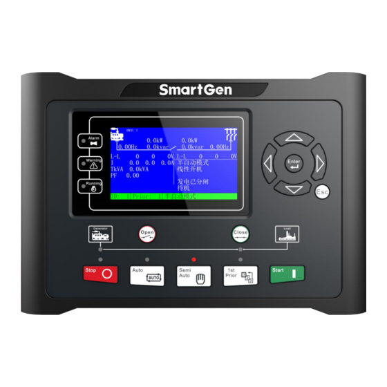
The leakage current is not more than 3mA within 1min. Weight 0.95kg OPERATION 5.1 PANEL DISPLAY TFT LCD: 4.3 inches with 480x272 resolutions, as follows: Fig.1 – HMC6 Panel Drawing HMC6 Power Management Controller User Manual Page 9 of 87... -
Page 10: Pushbuttons
2. Press it more than 3s and enter parameter setting menu; 3. In setting menu, confirm the set value. 1. Return to main menu; Exit 2. Return to previous menu in setting menu. HMC6 Power Management Controller User Manual Page 10 of 87... -
Page 11: Parameters Setting
>Stop Wait Delay Breaker setting >Onload Stable Delay Input setting >Transient Fault Delay Output setting >Heavy Consumer Delay Module setting >Alarm Start Delay Synchronization setting >Trigger Start Delay Synchronous calibration HMC6 Power Management Controller User Manual Page 11 of 87... - Page 12 (form 4). > Stop Output Delay >Start Wait Delay >Stop Wait Delay >Onload Stable Delay >Transient Fault Delay >Heavy Consumer Delay >Alarm Start Delay >Trigger Start Delay >Alarm Shutdown Delay HMC6 Power Management Controller User Manual Page 12 of 87...
-
Page 13: Dg System Mode Description
6.1.1 MANUAL MODE When manual mode signal is active, the system will work through manual mode. In this mode, HMC6 controller can only monitor data and alarm information but cannot control switch or engine. In addition, GOV and AVR do not work but the manual governor IN, manual governor OUT, manual VOLT IN and manual VOLT OUT do work in this mode. -
Page 14: Auto Mode
Auto Start Rules a) If the system detects that there is no voltage signal on busbar, then the available diesel generator units are started according to the start priority; HMC6 Power Management Controller User Manual Page 14 of 87... - Page 15 When stop input is activated in auto mode, system enters into “Stop Delay” state; b) After “Stop Delay” is expired, in case of multi-set operation, genset will be opened after transferring the load; HMC6 Power Management Controller User Manual Page 15 of 87...
- Page 16 In duty time start mode, genset will stop deactivated; The system will control GOV and when duty time is up. (details please to AVR automatically. see “Auto Start Rules”) HMC6 Power Management Controller User Manual Page 16 of 87...
-
Page 17: Start Mode Description
Х ● the additional genset which stored internal has the shortest running memory and cannot be hours at this time will be lost even in case of started. power outage; HMC6 Power Management Controller User Manual Page 17 of 87... -
Page 18: Sg System Mode Description
7.1 SG SYSTEM MODE 7.1.1 MANUAL MODE When Manual mode signal is active, the system will work through manual mode. In this mode, HMC6 controller can only monitor data and alarm information but cannot control switch or engine. In addition, GOV and AVR do not work but the manual governor IN, manual governor OUT, manual VOLT IN and manual VOLT OUT do work in this mode. -
Page 19: Auto Mode
In fixed power mode, SG will automatically start and connect to the grid with DG when the input of SG is effective with load; In load sharing mode, SG will automatically start and connect to the grid with DG when the input of SG is effective with load; HMC6 Power Management Controller User Manual Page 19 of 87... -
Page 20: Working Mode Description
Note: When in SG mode, outputs of GOV and AVR should be set as “none” if SG can not achive speed governing. PROTECTION Generator protection, busbar protection, current protection, power protection and switch protection can be provided by HMC6. Each kind of protection can configure one or more relays output. Table 8 – Controller Alarm types Alarm Type/Action Buzzer... - Page 21 Always active Warn When busbar frequency has fallen below than the set Underfreq 1 It is active after the switch value 1, it will initiate a warning alarm. has closed. HMC6 Power Management Controller User Manual Page 21 of 87...
- Page 22 Trip When genset voltage has fallen below than the set Undervolt 2 It is active after the switch value 2, it will initiate a trip alarm. has closed. HMC6 Power Management Controller User Manual Page 22 of 87...
- Page 23 When the controller detects that negative phase Trip Unbalanced current has exceeded the set value, it will initiate a It is active after the switch Current warning alarm. has closed. Power Protection HMC6 Power Management Controller User Manual Page 23 of 87...
- Page 24 Distribution of than the set value, the unbalanced reactive power unbalanced distribution of Reactive Power distribution outputs and alarms. reactive power is enabled. HMC6 Power Management Controller User Manual Page 24 of 87...
- Page 25 Module Protection When controller detects the power supply voltage has Warn Over Volt exceeded the set value, it will initiate a warning alarm. Always active HMC6 Power Management Controller User Manual Page 25 of 87...
- Page 26 When LA2 is enabled HMP300 Com When controller detects HMP300 module Warn Fail communication failure, it will initiate a warning alarm. When HMP300 is enabled HMC6 Power Management Controller User Manual Page 26 of 87...
-
Page 27: Hardware Structure
HARDWARE STRUCTURE 9.1 STRUCTURE DESCRIPTION HMC6 terminals are standard configuration. Uses only can expand 16-channels discrete input module, 16-channels discrete output module or 16-channels LED lamp module via CANBUS (Expand) port to realize expansion. Table 10 – HMC6 Terminals Slot... -
Page 28: Slot#1 Power Supply And Relay Output Port
COM port 3~5 NOTE: In case of using battery as power source, make the controller connect to the battery directly instead of start battery or charging generator to ensure stable supply of HMC6. 9.2.2 SLOT #2, SLOT #3 RELAY OUTPUT PORT Table 12 –... -
Page 29: Slot#4 Canbus Port, Gov Analog Portand Avr Analog Port
Function Description Remarks (MSC LINK) Multi-sets communication MSC LINK CANH port CANBUS COM port (MSC LINK) Used for data sharing between HMC6 controllers. CANL (MSC LINK) Expand CANBUS port (EXPANSION) Used for data sharing between HMC6 CANH CANBUS COM port controllers. -
Page 30: Slot#8 Digial Input, External Frequency/Voltage Modulation Inputs
Description Remarks COM port of Terminal 65、66 and COM8 AUX.OUTPUT4 Auxiliary output port 4 AC250V/8 A AUX.OUTPUT5 Auxiliary output port 5 AC250V/8 A AUX.OUTPUT6 Auxiliary output port 6 AC250V/8 A HMC6 Power Management Controller User Manual Page 30 of 87... -
Page 31: Slot#10 Rs485 Communication Port
RS485 shield port Shielded wire single-end earthed. 9.3 CONNECTION 9.3.1 TYPICAL APPLICATION DIAGRAM Fig. 4 – HMC6 Typical Diagram 9.3.2 AC WIRE CONNECTION (3 PHASE 3 WIRE) Fig. 5 – 3 Phase 3 Wire Connection HMC6 Power Management Controller User Manual... -
Page 32: Ac Wire Connection (Single Phase 2 Wire)
Fig.7 – 2 Phase 3 Wire Connection 9.3.5 ANALOG INPUT HMC6 FREQ IN and VOLT IN ports support -10V~10V analog voltage input function. External power supply must be fitted when input signal. Table 18 - FREQ IN and VOLT IN Function Description... - Page 33 0~10V input connection: 2kΩ 1/4W +10VDC 62/63 0VDC Fig.8 – 0~10V Input Connection Diagram -10V~10V input connection: 2kΩ 1/4W +10VDC 62/63 -10VDC 0VDC Fig.9 – -10V~10V Input Connection Diagram HMC6 Power Management Controller User Manual Page 33 of 87...
-
Page 34: Msc Link Port
9.3.6 MSC LINK PORT Data sharing and data communication functions among HMC6 controllers are implemented via MSC LINK (CANBUS port). Detailed connection way is as following: Fig.10 – HMC6 Module Communication Connection Diagram 9.3.7 MSC APPLICATION DIAGRAM Fig.11 – MSC Application Diagram... -
Page 35: Power Management And Workflow Chart
90% and the fixed output power percentage is 80%. According to the change of the total load, SG and SG on-load are as shown in the 5 parts of figure above: HMC6 Power Management Controller User Manual Page 35 of 87... -
Page 36: Synchronising
Heavy consumer equipment should send a heavy consumer request before starting up. Only binary input can be handled by HMC6 and the request value must be fixed load value. Each heavy consumer request can set a corresponding request power value and rated power value. -
Page 37: Heavy Consumer Permission
After the answer is active, the real power of the load is 30kW. There is 130kW redundancy on busbar, if stop condition is satisfied, the additional generator will be stopped. HMC6 Power Management Controller User Manual Page 37 of 87... - Page 38 If the heavy load feedback is inactive, the bus bar will only reserve the rated power for HC1 when heavy load request is active; h) If the heavy load feedback is inactive, the bus bar will not reserve any power for HC1 when heavy load request is inactive; HMC6 Power Management Controller User Manual Page 38 of 87...
-
Page 39: Trip Of Non Essential Load (Nel)
10.5 TRIP OF NON ESSENTIAL LOAD (NEL) The trip of Non Essential Load (NEL) groups is carried out in order to protect the busbar. Each HMC6 controller is able to handle three non-essential load trip (NEL). Trip priority is: NEL1> NEL2> NEL3. If the active power or current has exceeded the set value, the corresponding NEL will trip after the trip delay, and the warning alarm will be initiated. -
Page 40: Workflow Chart
Start Fail Alarm Start Success Load Stable Delay Meet with load Frequency Volt conditions Fault Normal Running Meet with load conditions Transient Fault Delay Breaker Close Fig.15 – System Start Workflow Chart HMC6 Power Management Controller User Manual Page 40 of 87... -
Page 41: Stop
CB Open Delay CB Open OK Open Fail Alarm Stop Output Delay Wait for Stop Delay Stop Fail Alarm Stop Success Stop Success Genset Stop Fig.16 – System Stop Workflow Chart HMC6 Power Management Controller User Manual Page 41 of 87... -
Page 42: Close Breaker
CB Close Success Alarm Load Sharing Mode Load Sharing Mode Output or Single Base Load Output Unit Running Alarm or Not Related Alarm Action Fig.17 – System Breaker Close Workflow Chart HMC6 Power Management Controller User Manual Page 42 of 87... -
Page 43: Open Breaker
OPEN BREAKER Start CB Open or Stop Active Ramp-off Load Blew Opening Load CB Open Delay CB Open Success Open Fail Alarm Stop Operation Fig.18 – System Breaker Open Workflow Chart HMC6 Power Management Controller User Manual Page 43 of 87... -
Page 44: Heavy Consumer
Calculation Satisfy HC Load HC Stable Delay Satisfy HC Load Start Backup HC Ack Output Gensets HC Feedback Active Schedule HC Rated Power Start/Stop Fig.19 – Heavy Consumer Workflow Chart HMC6 Power Management Controller User Manual Page 44 of 87... -
Page 45: Light Consumer
10.6.6 LIGHT CONSUMER Start Load Below Stop Set Value Light Consumer Active Gensets Parallel CB Open Running Fig.20 – Light Consumer Workflow Chart HMC6 Power Management Controller User Manual Page 45 of 87... -
Page 46: Scopes And Definitions Of Programmable Parameters
5: Safety Stop (0-1) Action 0: Disable 1:Enable 1: Enable Over Voltage 2 Set value (90-150)% Delay (0.1-100.0)s Alarm Type (0-5) 2:Trip Over Voltage 3 (0-1) Action 0:Disable 0: Disable HMC6 Power Management Controller User Manual Page 46 of 87... - Page 47 Alarm Type (0-5) 2:Trip (0-1) Action 0: Disable 0:Disbale Over 1: Enable Frequency 3 Set value (100-130)% Delay (0.1-100.0)s Alarm Type (0-5) 2:Trip Under (0-1) Action 1:Enable Frequency 1 0: Disable HMC6 Power Management Controller User Manual Page 47 of 87...
- Page 48 VECTOR SHIFT has exceeded VECTOR SHIFT Set value (0-20.0)° the set value, it will initiate a alarm signal and the alarm information will be displayed on LCD. Delay (0-20.0)s Alarm Type (0-5) 1:Warn HMC6 Power Management Controller User Manual Page 48 of 87...
-
Page 49: Timer Setting
Start delay caused by human triggered Operate Start Delay (0-3600)s (e.g. manual transfer priority, high consumer request and etc.) Stop delay caused by the trip or Alarm Stop Delay (0-3600)s shutdown alarms. HMC6 Power Management Controller User Manual Page 49 of 87... -
Page 50: Generator Setting
Detect when controller prepare loading. When Loading Frequency (0-200)% generator frequency under load frequency, it won’t enter into normal running. Crank Success Frequency (0-200)% To offer standards for detecting crank HMC6 Power Management Controller User Manual Page 50 of 87... - Page 51 Delay (0.1-100.0)s Alarm (0-5) 1:Warn Type (0-1) Action 0: Disable 1:Enable 1: Enable Under Set value (50-100)% Voltage 2 Set Delay (0.1-100.0)s Alarm (0-5) 2:Trip Type Under Action (0-1) 0:Disable HMC6 Power Management Controller User Manual Page 51 of 87...
- Page 52 (50-100)% Delay (0.1-100.0)s Alarm (0-5) 1:Warn Type (0-1) Action 0: Disable 1:Enable 1: Enable Under Frequency 2 Set value (50-100)% Delay (0.1-100.0)s Alarm (0-5) 2:Trip Type Under Action (0-1) 0:Disable HMC6 Power Management Controller User Manual Page 52 of 87...
- Page 53 Minimum can be adjusted after breaker is closed; (-10-10)V Adjust for the multi-units, reactive power can be adjusted after breaker is closed. Maximum (-10-10)V Adjust HMC6 Power Management Controller User Manual Page 53 of 87...
-
Page 54: Generator Load Setting
(0-5) 2:Trip (0-1) Action 0:Diable 1:Enable 1:Enable Over Current Set Value (50-300)% 3 Set Delay (0.1-999.9)s 30.0 Alarm Type (0-5) 2:Trip (0-1) Over Current Action 0:Diable 1:Enable 4 Set 1:Enable HMC6 Power Management Controller User Manual Page 54 of 87... - Page 55 1:Warn (0-1) External NEL 1 trip is active when the NEL 1 Trip Action 0: Disable 1:Enable active power of any busbar genset has 1: Enable exceeded the set value. HMC6 Power Management Controller User Manual Page 55 of 87...
- Page 56 Power Delay Value (0-999.9)s 60.0 Alarm Types (0-5) 1: Warn Heavy Consumer 1 Analog (0-1) 0: Disable Feedback of heavy load 1 obtains the HMC6 Power Management Controller User Manual Page 56 of 87...
-
Page 57: Setting
After the open signal is send out, warning alarm will be initiated if the controller does not detect the switch opening signal within the set delay. HMC6 Power Management Controller User Manual Page 57 of 87... -
Page 58: Module Setting
0: Disable 0: Disable DIN16-1 Enabled 1: Enable Connect with extension module DIN16-1 Alarm Delay (0.1~999.9)s when input ports of HMC6 are not enough; If still not enough, the external DIN16-2 is (0-1) Extension Module extended. 0: Disable 0: Disable... - Page 59 1:Enable (0-1) When it is enabled, the function of Terminal T54 Is Ready 0:Disable 0: Disable 54 will change from ‘ Engine Fault Input‘ to 1:Enable ‘Unit is Ready Input’. HMC6 Power Management Controller User Manual Page 59 of 87...
- Page 60 Gen Active Power Gen Inactive Power Gen Apparent Power Gen Power Factor Gen Phase-A Current Gen Phase-B Current Gen Phase-C Current Gen Max. Current Busbar Surplus Power Unit Surplus Power Reserved Reserved HMC6 Power Management Controller User Manual Page 60 of 87...
-
Page 61: Input Ports Setting
(0-1) 0: Close activate 1: Open activate Programmable Input 8 (Multiplexing with voltage modulation VOLT IN+) Contents Setting (0-99) Not used Active Type (0-1) 0: Close activate 1: Open activate HMC6 Power Management Controller User Manual Page 61 of 87... - Page 62 After breaker closing, feedback signal is send to HC 2 Feedback Х ● ● controller to ensure the HC2 has loaded. HC 3 Request Heavy consumer 3 request. Х ● ● HMC6 Power Management Controller User Manual Page 62 of 87...
- Page 63 The signal output when the preparation work is Ready OK Х ● ● done. If the function is selected, the engine will be HMC6 Power Management Controller User Manual Page 63 of 87...
- Page 64 When input is active, limit genset network Limit Network connected number based on configuration (max. Х ● ● Connected No. network connected number); Engine Running Х ● ● Feedback HMC6 Power Management Controller User Manual Page 64 of 87...
- Page 65 ● ● supply units. When input port is active, DG controller detects that Busbar Outage the busbar is outage then allows DG switch to Х ● ● Closing Input close. HMC6 Power Management Controller User Manual Page 65 of 87...
-
Page 66: Output Port Setting
Contents Setting Fixed Fixed Open Gen Active Type (0-1) 0: Open 1: Close Aux. output 9 Contents Setting (0-150) Common Alarm Active Type (0-1) 0: Open 1: Close Programmable Output 1 HMC6 Power Management Controller User Manual Page 66 of 87... - Page 67 Active when genset is stopping. Active when the power supply voltage has exceeded Power Over Volt the set value. Active when the power supply voltage has fallen below Power Under Volt the set value. HMC6 Power Management Controller User Manual Page 67 of 87...
- Page 68 Busbar Over Frequency 2 occurs. Active when the busbar over frequency 3 alarm Busbar Over Frequency 3 occurs. Active when the Busbar under frequency 1 alarm Busbar Under Frequency 1 occurs. HMC6 Power Management Controller User Manual Page 68 of 87...
- Page 69 Active when non-essential load 1 trip occurs. NEL 2 Trip Active when non-essential load 2 trip occurs. NEL 3 Trip Active when non-essential load 3 trip occurs. Engine Fault Active when engine fault signal is output. HMC6 Power Management Controller User Manual Page 69 of 87...
- Page 70 Audible Alarm acknowledge. 106. Failed to Unload 107. Unload Output When controller detects all normal gensets are online, 108. Gen Capacity Insufficient and remaining power cannot request power, this outputs. HMC6 Power Management Controller User Manual Page 70 of 87...
- Page 71 NEL 3 Pre-tripping DIN16-1 IN1 Active DIN16-1 IN2 Active DIN16-1 IN3 Active Outputs when DIN16-1 module input is active. DIN16-1 IN4 Active DIN16-1 IN5 Active HMC6 Power Management Controller User Manual Page 71 of 87...
-
Page 72: Synchronization Setting
Ladder point of genset ramp on/off load. Delay Percent Load Ramp Rate Delay time of per ladder point of genset ramp (0-30)s Delay Value on/off load. Multi-unit Communication (1-16) The unit number of MSC bus. Amount HMC6 Power Management Controller User Manual Page 72 of 87... - Page 73 Highest Priority (0-1) refresh. If disabled this function, it will make current genset priority become higher, but not change HMC6 Power Management Controller User Manual Page 73 of 87...
- Page 74 The proportion of load frequency adjustment PID Load (P) Feedback (0-100)% coefficient in the whole load active power Factor adjustment coefficient. Load (Q) Feedback (0-100)% The proportion of load voltage adjustment PID HMC6 Power Management Controller User Manual Page 74 of 87...
- Page 75 When it is enabled, the Min. Load Percentage= Shutdown Current Power (Total Power- Power of Unit to (0-1) Percentage Rest Stop); When it is disabled, the Min. Load Percentage= Current Power/Total Power. HMC6 Power Management Controller User Manual Page 75 of 87...
-
Page 76: Synchronous Calibration
Stability (0-2000) % connection. Response (0.1-4.00)Hz/s 1.20 Relay Stability (0.01-1.60)s 0.20 The internal relay is adjusted to control the Control engine speed after parallel connection. Gain (0-30000)% Dead Band (0-10.0)% HMC6 Power Management Controller User Manual Page 76 of 87... - Page 77 Receiving than receiving rated power percentage( the setting value) before SG is closing. 19 DG Stop% When SG (0-100.0)% 50.0 When the controller works in both SG mode HMC6 Power Management Controller User Manual Page 77 of 87...
-
Page 78: Local Setting
(0-5) 3: HMC6000A; 4: HMC6000ED; 5: HMC6000EG; 11.12 DIN16 SETTING HMC6 can expand with two DIN16 modules (digital input expansion module), which has the same input functions with HMC6. Table 33 – DIN16 Parameter Settings Items Parameter Range Default Description... - Page 79 0: close activate;1: open activate. Input Port 16 Contents Setting (0-99) Not used Active Type (0-1) 0: close activate;1: open activate. Note: input port functions please reference to Input port function setting. HMC6 Power Management Controller User Manual Page 79 of 87...
-
Page 80: Dout16 Setting
11.13 DOUT16 SETTING HMC6 can expand with two DOUT16 modules (digital output expansion module), which has the same output functions with HMC6. Table 34 – DOUT16 Parameter Settings Items Parameter Range Default Description Output Port 1 Contents Setting (0-150) Not Used... - Page 81 0: open; 1: close. Output Port 16 Contents Setting (0-150) Not Used Active Type (0-1) 0: open; 1: close. te: output port functions please reference to Output port function list in item11.8. HMC6 Power Management Controller User Manual Page 81 of 87...
-
Page 82: La16 Setting
11.14 LA16 SETTING HMC6 can expand with two LA16 modules (LED display expansion module), which has the same configure content with HMC6. Table 35 – LA16 settings Items Parameter Range Default Description Output 1 Contents Setting (0-150) Not used Active Type (0-1) 0: open;... -
Page 83: User-Defined Protocal Setting
3500-3749 is created. The user-defined data address is configured by the host computer, and users can read user-defined data sequence through addresses 3500-3749. HMC6 Power Management Controller User Manual Page 83 of 87... - Page 84 User-defined 2Bytes User-defined 3514 2Bytes 3515 User-defined 2Bytes 3516 User-defined 2Bytes 3517 User-defined 2Bytes 3518 User-defined 2Bytes 3519 User-defined 2Bytes 3520 User-defined 2Bytes User-defined 3521 2Bytes User-defined 3522-3749 2*N Bytes HMC6 Power Management Controller User Manual Page 84 of 87...
-
Page 85: Commissioning
During parallel operation off load, check that there is no high circumfluence on HMC6 current screen; During parallel operation off load, check if the output of active and reactive power is equal to zero; if it is not, then check if there is power oscillation;... -
Page 86: Installation
Fig.21 - Installation Dimensions Battery Voltage Input NOTE: HMC6 controller can suit for widely range of battery voltage (8~35) VDC. The wire’s diameter must be over 1.5mm and which is connected to B+ and B- of controller power. -
Page 87: Fault Finding
Check RS485’s connections of A and B is reverse connect or not; abnormal Check RS485 transfer model whether damage or not; Check communication port of PC whether damage. _________________________________ HMC6 Power Management Controller User Manual Page 87 of 87...
Need help?
Do you have a question about the HMC6 and is the answer not in the manual?
Questions and answers