Table of Contents
Advertisement
Quick Links
Advertisement
Table of Contents

Related Manuals for Smartgen HAT520N


Summary of Contents for Smartgen HAT520N
- Page 1 HAT520N ATS CONTROLLER USER MANUAL SMARTGEN (ZHENGZHOU) TECHNOLOGY CO., LTD.
-
Page 2: Table Of Contents
HAT520N ATS CONTROLLER USER MANUAL CONTENT OVERVIEW ............................4 PERFORMANCE AND CHARACTERISTICS ..................4 SPECIFICATION ..........................5 PANEL DESCRIPTION ........................6 PANEL OPERATION ........................ 6 INDICATOR LIGHT FUNCTION DESCRIPTION ..............6 PANEL BUTTON OPERATION ......................7 PANEL BUTTON OPERATION ....................7 PRIORITY SETTING ........................ -
Page 3: Overview
As default, phase sequence wrong protection and over/under frequency protection are disable; however, users can set the protection function as need. c) With LINK communication port (with SmartGen SG72 adapter). Parameters can be set via PC software and also can realize firmware update of controller. -
Page 4: Specification
HAT520N ATS CONTROLLER USER MANUAL 3 SPECIFICATION HAT520N Controller Specifications Items Contents Operating Voltage AC170V~277V during AC power L1N1/L2N2 supply. Power Consumption <2W (Standby mode: <1W) AC Voltage Input 3P4W (ph-N) AC170V~AC277V(ph-N) 1P2W (ph-N) AC170V~AC277V (ph-N) 2P3W (ph-N) AC170V~AC277V(ph-N) Rated Frequency... -
Page 5: Panel Description
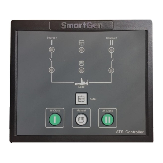
HAT520N ATS CONTROLLER USER MANUAL 4 PANEL DESCRIPTION PANEL OPERATION Panel Description INDICATOR LIGHT FUNCTION DESCRIPTION Indicators Function Description Indicator Light Function Description It is illuminated when 1# power is normal; flashing when 1# power state is 1# Power Indicator abnormal;... -
Page 6: Panel Button Operation
HAT520N ATS CONTROLLER USER MANUAL 5 PANEL BUTTON OPERATION PANEL BUTTON OPERATION Pressing and holding the button for more than 3s, all LEDs are illuminated to enter into lamp test mode; under this mode, the controller will back to normal status automatically after release the button. -
Page 7: Ac System Setting
HAT520N ATS CONTROLLER USER MANUAL AC SYSTEM SETTING AC system can be set only when the controller is in parameters setting status. Procedures of setting “Single-phase 2-wire”,“3-phase 4-wire” and “2-phase 3-wire”: a) Press at the same time, when 1#/2#power indicator and auto indicator are illuminated;... -
Page 8: Delay Adjustment
HAT520N ATS CONTROLLER USER MANUAL DELAY ADJUSTMENT Delay value can be set only when the controller is in parameters setting status. Adjusting “1# power normal delay” potentiometer (locate nearby the back panel terminal) can set output delay after 1# power supply is normal. -
Page 9: Programmed Parameter And Range
HAT520N ATS CONTROLLER USER MANUAL 6 PROGRAMMED PARAMETER AND RANGE Parameter Configuration Item Range Default Description Can be set It is the delay of 1# power from voltage 1# Normal Delay (0-60)s via controller abnormal to voltage normal. Generally, it is potentiometer 10s. -
Page 10: Operation Control
1. 2# Priority; 2. NO Priority NOTE1: Parameters above configured by SmartGen PC software. PC program connection: LINK interface of SG72 connect with the interface of Controller. NOTE2: “1# Normal Delay” and “2# Normal Delay” can be set only via the potentiometer which locate nearby the back panel terminal. -
Page 11: Description Of Connecting Terminals
HAT520N ATS CONTROLLER USER MANUAL 8 DESCRIPTION OF CONNECTING TERMINALS HAT520N BACK PANEL Terminal Description Items Description Remark 1# Close Output Volt-free relay contact output N/O contact output; rated 16A. 2# Close Output Volt-free relay contact output N/O contact output; rated 16A. -
Page 12: Typical Wiring Diagram
HAT520N ATS CONTROLLER USER MANUAL 9 TYPICAL WIRING DIAGRAM SGQ-N/T Wiring Diagram SGQ-M Wiring Diagram HAT520N ATS Controller Version 1.1 2017-08-02 Page 13 of 15... -
Page 13: Installation
2-phase 3-wire Wiring Diagram Single phase 2-wire Wiring Diagram NOTE:Above pictures take the AC 220V voltage as example. If AC 110V voltage is applied in actual use, please contact with SmartGen technical staff to get the specific wiring methods. 10 INSTALLATION Installation Dimension HAT520N ATS Controller Version 1.1... -
Page 14: Fault Finding
HAT520N ATS CONTROLLER USER MANUAL 11 FAULT FINDING Common Faults Symptom Possible Solutions Controller no response with power. Check starting batteries. Genset running while ATS not Check ATS; transfer Check the connection wirings between the controller and the ATS. Electrical...
Need help?
Do you have a question about the HAT520N and is the answer not in the manual?
Questions and answers