Table of Contents
Advertisement
Advertisement
Table of Contents

Related Manuals for Smartgen HAT530N


Summary of Contents for Smartgen HAT530N
- Page 1 HAT530N ATS CONTROLLER USER MANUAL SMARTGEN (ZHENGZHOU) TECHNOLOGY CO., LTD.
- Page 2 SmartGen Technology at the address above. Any reference to trademarked product names used within this publication is owned by their respective companies. SmartGen Technology reserves the right to change the contents of this document without prior notice. Table1 - Software Version Date...
-
Page 3: Table Of Contents
HAT530N ATS CONTROLLER USER MANUAL CONTENT OVERVIEW ............................4 PERFORMANCE AND CHARACTERISTICS ..................4 SPECIFICATION ..........................5 OPERATING ............................6 OPERATION PANEL ........................ 6 INDICATORS DESCRIPTION....................6 PANEL BUTTON OPERATION ......................7 PANEL OPERATION ........................ 7 PRIORITY SETTING ........................ 7 AC SYSTEM SETTING ...................... -
Page 4: Overview
HAT530N ATS CONTROLLER USER MANUAL OVERVIEW The powerful Microprocessor contained within the HAT530N ATS controller allows for precision voltage (2-way 3-phase/single phase) measuring and make accurate judgment on abnormal voltage (power lost, over/under voltage, over/under frequency, loss of phase, phase sequence wrong) and control ATS to transfer after the delay has expired. -
Page 5: Specification
HAT530N ATS CONTROLLER USER MANUAL SPECIFICATION Table 2 – Product Specification Items Contents Operating Voltage AC170V~277V during AC power L1N1/L2N2 supply. Power Consumption <3W (Standby mode: <1W) AC Voltage Input 3P4W (ph-N) AC170V~AC277V(ph-N) 1P2W (ph-N) AC170V~AC277V (ph-N) 2P3W (ph-N) AC170V~AC277V(ph-N) -
Page 6: Operating
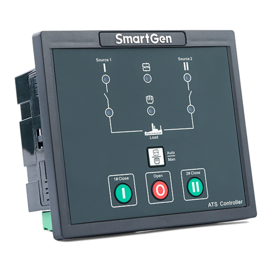
HAT530N ATS CONTROLLER USER MANUAL OPERATING 4.1 OPERATION PANEL Fig.1 – HAT530N Panel Drawing 4.2 INDICATORS DESCRIPTION Table 3 – Indicator Function Description in Normal Testing Mode Items Description It is illuminated when 1# power is normal; flashing when 1# power state is 1# Power Indicator abnormal;... -
Page 7: Panel Button Operation
HAT530N ATS CONTROLLER USER MANUAL PANEL BUTTON OPERATION 5.1 PANEL OPERATION Pressing and holding the button for more than 3s, all LEDs are illuminated to enter into lamp test mode; under this mode, the controller will back to normal status automatically after release the button. -
Page 8: Ac System Setting
HAT530N ATS CONTROLLER USER MANUAL 5.3 AC SYSTEM SETTING AC system can be set only when the controller is in parameters setting status. Procedures of setting ―Single-phase 2-wire‖,―3-phase 4-wire‖ and ―2-phase 3-wire‖: a) Press at the same time, when 1#/2# power indicator and auto indicator are illuminated;... -
Page 9: Factory Reset Delay Value
HAT530N ATS CONTROLLER USER MANUAL After adjusting the delays, press . When 1#/2#power indicator and automatic indicator are illuminated simultaneously, the adjusted value has been saved. The controller will back to normal status automatically after all LEDs are flashing 5 times rapidly and controller will work according to the set delay values. -
Page 10: Parameter Configeration
HAT530N ATS CONTROLLER USER MANUAL PARAMETER CONFIGERATION 6.1 PARAMETERS TABLE Table 4 – Parameters Setting Table Item Range Default Description Can be set via It is the delay of #1 power from voltage 1# Normal Delay (0-60)s controller abnormal to voltage normal. Generally, it is 10s. - Page 11 (0-23) OUTPUT FUNCTION DESCRIPTION Note1: Parameters above are configured via PC software of SmartGen. The PC programming connection is use LINK interface of SG72 module connect with LINK interface of controller. Note2: “1# Normal Delay” and “2# Normal Delay” can be set only via the potentiometer which locate nearby the back panel terminal.
-
Page 12: Output Function Description
HAT530N ATS CONTROLLER USER MANUAL 6.2 OUTPUT FUNCTION DESCRIPTION Table 5 – Output Function Description Items Description 00. Not used Invalid. 01. 1# Normal volt It will output when1# voltage is normal. 02. 1# Abnormal volt It will output when 1# voltage is abnormal. -
Page 13: Description Of Connecting Terminals
HAT530N ATS CONTROLLER USER MANUAL DESCRIPTION OF CONNECTING TERMINALS Fig.2 – HAT530N Rare Panel Drawing Table 6 - Terminal Function Table Items Description Remark Volt-free relay contact output; Aux. Output 1 Default: ATS Power A Phase Rated 16A. Volt-free relay contact output;... -
Page 14: Ats Power Supply
HAT530N ATS CONTROLLER USER MANUAL Items Description Remark LINK Communication Port Communicate with PC/Program update ATS POWER SUPPLY The power of ATS is supplied by controller, as long as one power is normal, this can ensure ATS power supply normally and can be transferred properly. -
Page 15: Typical Wiring Diagram
HAT530N ATS CONTROLLER USER MANUAL 10 TYPICAL WIRING DIAGRAM Fig.5 - ATySM3s Wiring Diagram Fig.6 - ATyS3s Wiring Diagram HAT530N ATS CONTROLLER 2018-05-25 Version 1.1 Page 15 of 17... - Page 16 Fig.9 - Single phase 2-wire Wiring Diagram Note:Above pictures take the AC 220V voltage as example. If AC 110V voltage is applied in actual use, please contact with SmartGen technical staff to get the specific wiring methods. HAT530N ATS CONTROLLER 2018-05-25 Version 1.1...
-
Page 17: Installation
HAT530N ATS CONTROLLER USER MANUAL 11 INSTALLATION Fig.10 - Installation Dimensions 12 FAULT FINDING Table 7 – Fault Finding Symptom Possible Solutions Controller no response with power. Check controller wring. Genset running while ATS not Check ATS; Check the connection wirings between the controller transfer and the ATS.
Need help?
Do you have a question about the HAT530N and is the answer not in the manual?
Questions and answers